2002 LAND ROVER DISCOVERY air filter
[x] Cancel search: air filterPage 1275 of 1672
PANEL REPAIRS
77-2-26 REPAIRS
Headlamp mounting panel - LH
Remove
1.Disconnect both battery leads, negative lead
first.
2.Disconnect leads/multiplug from alternator.
3.Remove washer reservoir.
+ WIPERS AND WASHERS, REPAIRS,
Reservoir - washer - up to 03MY.
4. Models with A/C: Remove condensor.
+ AIR CONDITIONING, REPAIRS,
Condenser.
5. Diesel models: Remove gearbox fluid cooler.
6.Remove headlamp.
+ LIGHTING, REPAIRS, Headlamp - up
to 03MY.
7.Remove repeater lamp.
+ LIGHTING, REPAIRS, Lamp - front
repeater.
8.Release headlamp levelling motor and position
aside.
9.Release headlamp wiring and position aside.
10.Remove air filter assembly.
+ ENGINE MANAGEMENT SYSTEM -
Td5, REPAIRS, Air filter assembly.
+ ENGINE MANAGEMENT SYSTEM -
V8, REPAIRS, Air cleaner assembly.
11.Remove 2 earth leads from LH of front
bulkhead.
12.Release and remove A/C pipes.
13.Remove crush can.
14.Remove bonnet release cable.
15.Remove 2 bolts securing front bulkhead
assembly to chassis.
16.Remove centre brace.Repair
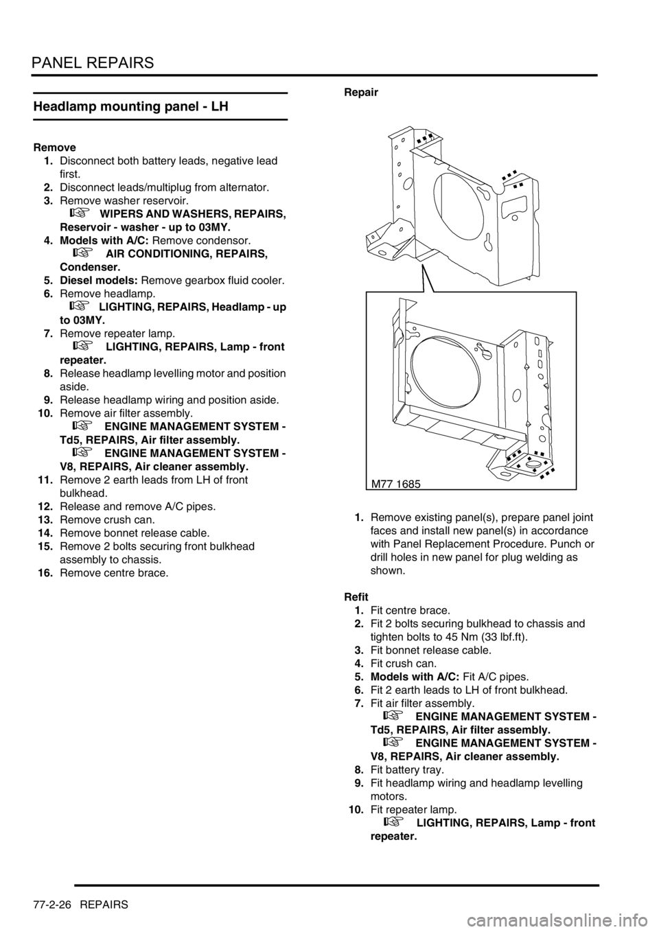
1.Remove existing panel(s), prepare panel joint
faces and install new panel(s) in accordance
with Panel Replacement Procedure. Punch or
drill holes in new panel for plug welding as
shown.
Refit
1.Fit centre brace.
2.Fit 2 bolts securing bulkhead to chassis and
tighten bolts to 45 Nm (33 lbf.ft).
3.Fit bonnet release cable.
4.Fit crush can.
5. Models with A/C: Fit A/C pipes.
6.Fit 2 earth leads to LH of front bulkhead.
7.Fit air filter assembly.
+ ENGINE MANAGEMENT SYSTEM -
Td5, REPAIRS, Air filter assembly.
+ ENGINE MANAGEMENT SYSTEM -
V8, REPAIRS, Air cleaner assembly.
8.Fit battery tray.
9.Fit headlamp wiring and headlamp levelling
motors.
10.Fit repeater lamp.
+ LIGHTING, REPAIRS, Lamp - front
repeater.
Page 1276 of 1672
PANEL REPAIRS
REPAIRS 77-2-27
11.Fit headlamp.
+ LIGHTING, REPAIRS, Headlamp - up
to 03MY.
12. Diesel models: Fit gearbox fluid cooler.
13. Models with A/C: Fit condensor.
+ AIR CONDITIONING, REPAIRS,
Condenser.
14.Fit washer reservoir.
+ WIPERS AND WASHERS, REPAIRS,
Reservoir - washer - up to 03MY.
15.Connect leads/multiplug to alternator.
16.Connect battery leads, negative lead last.
Valance upper assembly - LH
In this procedure, the front wing, the valance outer
reinforcement and the bonnet alarm switch mounting
bracket are replaced in conjunction with the LH
valance upper assembly.
Remove
1.Disconnect both battery leads, negative lead
first.
2.Disconnect leads/multiplug from alternator.
3.Remove front wing.
+ EXTERIOR FITTINGS, REPAIRS,
Wing - front - up to 03MY.
4.Remove air filter assembly.
+ ENGINE MANAGEMENT SYSTEM -
V8, REPAIRS, Air cleaner assembly.
+ ENGINE MANAGEMENT SYSTEM -
Td5, REPAIRS, Air filter assembly.
5.Remove PAS/ACE reservoir.
6.Remove ABS modulator.
+ BRAKES, REPAIRS, Modulator unit
- ABS.
7.Remove brake pipes from valance.
8.Release harness from valance and position
aside.
9. Models with A/C: Depressurise A/C system
and remove pipes from valance.
+ AIR CONDITIONING, REFRIGERANT
RECOVERY, RECYCLING AND
RECHARGING, Refrigerant recovery,
recycling and recharging.
Page 1277 of 1672
PANEL REPAIRS
77-2-28 REPAIRS
Repair
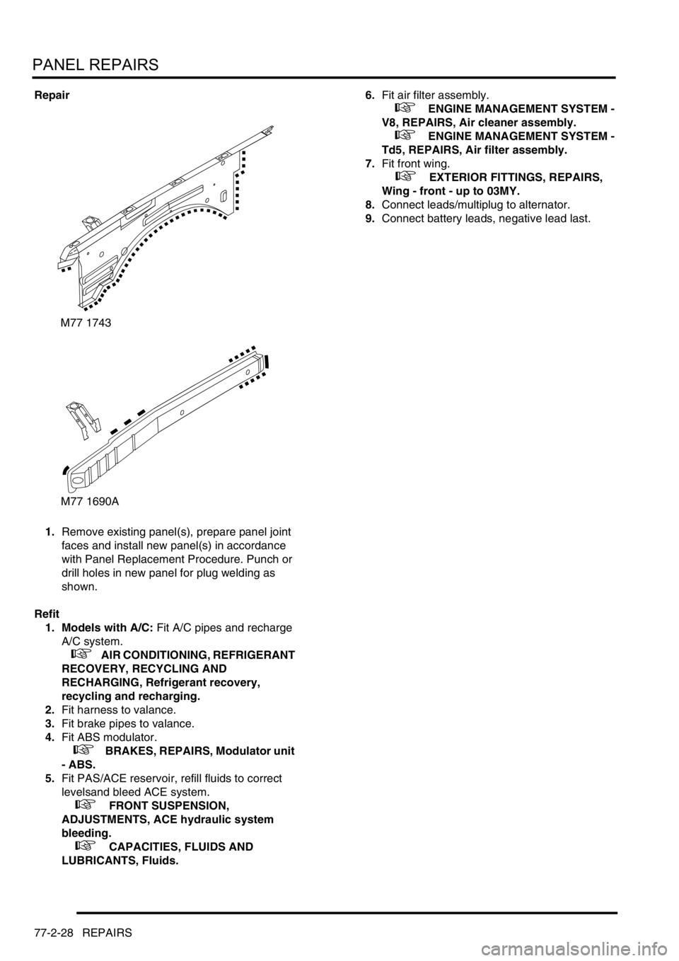
1.Remove existing panel(s), prepare panel joint
faces and install new panel(s) in accordance
with Panel Replacement Procedure. Punch or
drill holes in new panel for plug welding as
shown.
Refit
1. Models with A/C: Fit A/C pipes and recharge
A/C system.
+ AIR CONDITIONING, REFRIGERANT
RECOVERY, RECYCLING AND
RECHARGING, Refrigerant recovery,
recycling and recharging.
2.Fit harness to valance.
3.Fit brake pipes to valance.
4.Fit ABS modulator.
+ BRAKES, REPAIRS, Modulator unit
- ABS.
5.Fit PAS/ACE reservoir, refill fluids to correct
levelsand bleed ACE system.
+ FRONT SUSPENSION,
ADJUSTMENTS, ACE hydraulic system
bleeding.
+ CAPACITIES, FLUIDS AND
LUBRICANTS, Fluids.6.Fit air filter assembly.
+ ENGINE MANAGEMENT SYSTEM -
V8, REPAIRS, Air cleaner assembly.
+ ENGINE MANAGEMENT SYSTEM -
Td5, REPAIRS, Air filter assembly.
7.Fit front wing.
+ EXTERIOR FITTINGS, REPAIRS,
Wing - front - up to 03MY.
8.Connect leads/multiplug to alternator.
9.Connect battery leads, negative lead last.
M77 1743
M77 1690A
Page 1279 of 1672
PANEL REPAIRS
77-2-30 REPAIRS
Valance upper assembly (front section) -
LH
In this procedure, the front wing, the valance outer
reinforcement (front section) and the bonnet alarm
switch mounting bracket are replaced in conjunction
with the LH valance upper assembly (front section).
Remove
1.Disconnect both battery leads, negative lead
first.
2.Disconnect leads/multiplug from alternator.
3.Remove front wing.
+ EXTERIOR FITTINGS, REPAIRS,
Wing - front - up to 03MY.
4.Remove air filter assembly.
+ ENGINE MANAGEMENT SYSTEM -
Td5, REPAIRS, Air filter assembly.
+ ENGINE MANAGEMENT SYSTEM -
V8, REPAIRS, Air cleaner assembly.
5.Remove PAS/ACE reservoir.
6.Remove ABS modulator.
+ BRAKES, REPAIRS, Modulator unit
- ABS.
7.Release harness from valance and position
aside.
8. Models with A/C: Depressurise A/C system
and remove pipes from valance.
+ AIR CONDITIONING, REFRIGERANT
RECOVERY, RECYCLING AND
RECHARGING, Refrigerant recovery,
recycling and recharging.Repair
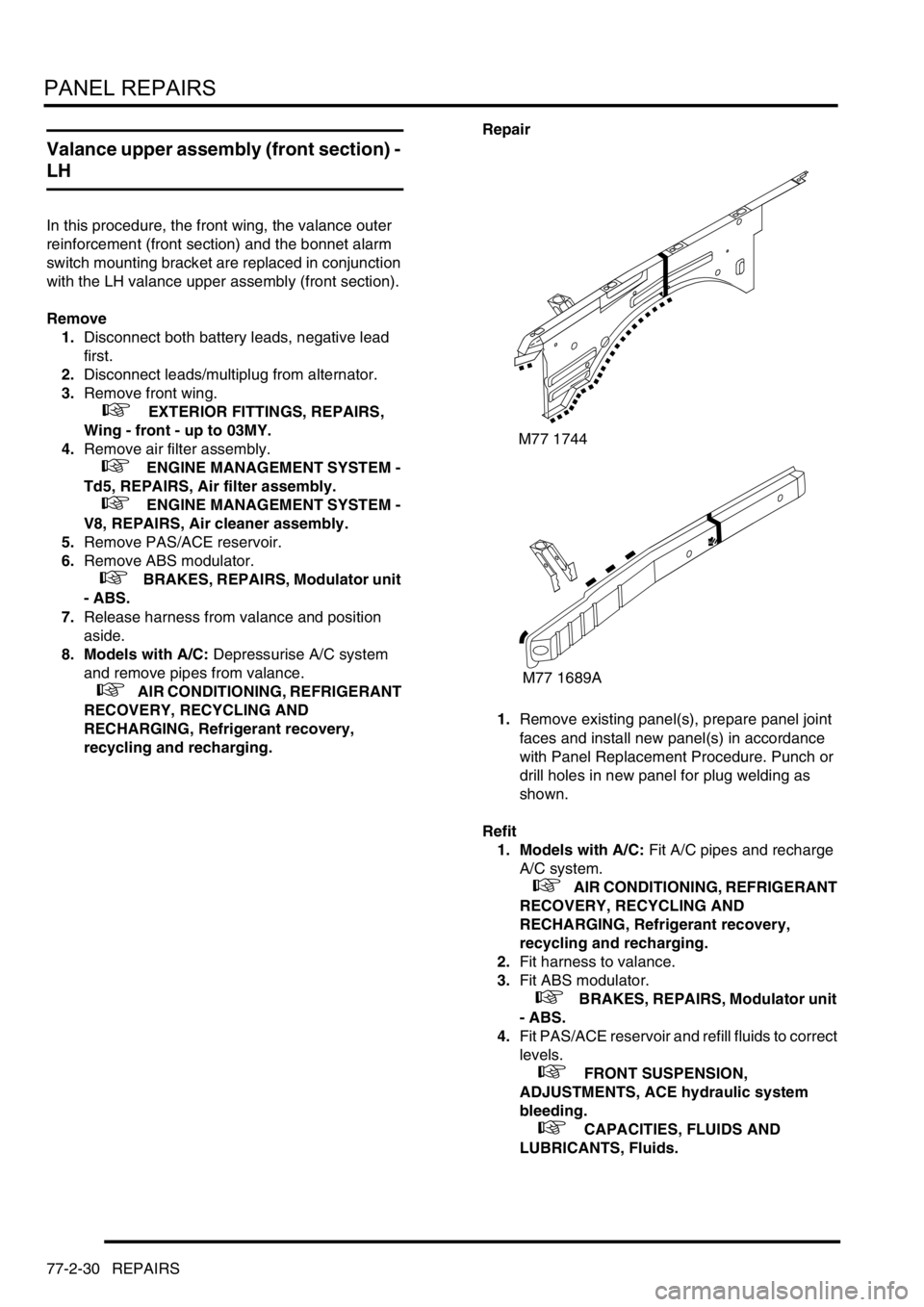
1.Remove existing panel(s), prepare panel joint
faces and install new panel(s) in accordance
with Panel Replacement Procedure. Punch or
drill holes in new panel for plug welding as
shown.
Refit
1. Models with A/C: Fit A/C pipes and recharge
A/C system.
+ AIR CONDITIONING, REFRIGERANT
RECOVERY, RECYCLING AND
RECHARGING, Refrigerant recovery,
recycling and recharging.
2.Fit harness to valance.
3.Fit ABS modulator.
+ BRAKES, REPAIRS, Modulator unit
- ABS.
4.Fit PAS/ACE reservoir and refill fluids to correct
levels.
+ FRONT SUSPENSION,
ADJUSTMENTS, ACE hydraulic system
bleeding.
+ CAPACITIES, FLUIDS AND
LUBRICANTS, Fluids.
M77 1744
M77 1689A
Page 1280 of 1672
PANEL REPAIRS
REPAIRS 77-2-31
5.Fit air filter assembly.
+ ENGINE MANAGEMENT SYSTEM -
Td5, REPAIRS, Air filter assembly.
+ ENGINE MANAGEMENT SYSTEM -
V8, REPAIRS, Air cleaner assembly.
6.Fit front wing.
+ EXTERIOR FITTINGS, REPAIRS,
Wing - front - up to 03MY.
7.Connect leads/multiplug to alternator.
8.Connect battery leads, negative lead last.
Valance upper assembly (front section) -
RH
In this procedure, the front wing and the valance
outer reinforcement (front section) are replaced in
conjunction with the RH valance upper assembly
(front section).
Remove
1.Disconnect both battery leads, negative lead
first.
2.Disconnect leads/multiplug from alternator.
3.Remove front wing.
+ EXTERIOR FITTINGS, REPAIRS,
Wing - front - up to 03MY.
4.Remove battery.
+ CHARGING AND STARTING,
REPAIRS, Battery.
5.Remove battery tray.
6.Remove fuse box.
7.Release expansion tank from fixings and
position aside.
8.Release harness from valance and position
aside.
Page 1312 of 1672
BODY SEALING MATERIALS
MATERIALS AND APPLICATIONS 77-3-5
Cooper Pegler Falcon Junior Pneumatic Gun (Airless)
Intended primarily for applying transit wax, this pneumatic sprayer has a 5-litre container with integral hand pump and
provides an effective means of wax spraying without the need for compressed air or additional services.
A selection of nozzles, lances, hose lengths and a trigger valve assembly with integral filter allows flexibility in use.
Additional applications include general maintenance, wax injection and paint application. Heavy-bodied materials
may also be applied. All parts are fully replaceable and a wide range of nozzle configurations is available.
SATA Schutz Gun Model UBE
The SATA Schutz Gun is approved for the retreatment of vehicle underbody areas with protective coatings as
supplied in 1 litre, purpose-designed 'one-way' containers. The screw thread fitting (female on the gun) is standard
to most Schutz-type packs.
SATA HKD1 Wax Injection Injection Equipment
This equipment is approved for carrying out cavity wax re-treatment. The SATA HKD1 set comprises a high quality
forged gun with 1-litre pressure feed container, a flexible nylon lance, a straight 1100 mm (43.307 in) steel lance and
hooked- wand lance. A quick-change coupling is provided as a standard fitting to allow lances to be easily
interchanged. Each lance has an integral, machined nozzle with specialised spray characteristics to suit the type of
box section to be treated.
NOTE: Always clean gun after use with appropriate solvent to maintain efficiency.
Specifications of Model UBE:
Air consumption 7 ft
3/min (200 litres/min) @ 45 lbf.in2
Weight: 23.3oz (220 grams)
Page 1399 of 1672

AIR CONDITIONING
82-26DESCRIPTION AND OPERATION
The rear evaporator/blower assembly cools and dehumidifies air from the cabin and supplies it to the rear distribution
system. The unit is installed on the left side of the loadspace, behind the quarter trim. A grille in the quarter trim allows
air to flow from the loadspace into the evaporator/blower. Refrigerant lines for the evaporator and a condensate drain
tube are attached to the rear floor.
The evaporator and blower are installed in a common housing, which also incorporates the resistor pack for the
blower. A thermostatic expansion valve is integrated into the inlet refrigerant line. A rear blower relay is attached to
the top of the housing.
Evaporator
The evaporator absorbs heat from the recirculated air being supplied to the distribution ducts.
Thermostatic expansion valve
The thermostatic expansion valve meters the flow of refrigerant into the evaporator to match the heat load of the air
passing through the evaporator matrix. A capillary tube, attached to the outlet pipe of the evaporator and connected
to the thermostatic expansion valve, automatically adjusts the valve opening in relation to the refrigerant temperature
at the evaporator outlet.
Blower
The blower controls the volume of air being supplied to the distribution outlets. The blower is an open hub, centrifugal
fan powered by an electric motor. A dust filter is installed over the fan inlet. The blower switch on the control panel
and the resistor pack control the operation of the blower, which can be selected to run at one of four speeds.
Resistor pack
The resistor pack supplies reduced voltages to the blower motor for blower speeds 1, 2 and 3. For blower speed 4,
the resistor pack is bypassed and battery voltage drives the motor at full speed. The pack is installed in the air outlet
from the blower fan, so that any heat generated is dissipated by the air flow.
Distribution system
Air ducts
Ducts connected to the rear evaporator/blower motor assembly distribute air to five vent assemblies in the roof.
Vent assemblies
The vent assemblies allow occupants to control the flow and direction of air. Each vent assembly incorporates a
thumbwheel to regulate flow and moveable vanes to control direction.
Rear control system
The control system operates the blower to control the operation of the rear A/C. The control system consists of two
control switches and a rear blower relay.
Control switches
A rear A/C switch and a blower speed switch are installed on a control panel in the roof lining. The A/C switch is a
latching pushswitch with an amber indicator lamp which illuminates when rear A/C is selected on. The blower speed
switch is a slide switch with a positive detent at each of four speed positions (there is no off position).
Rear blower relay
The rear blower relay controls the electrical supply to the blower.
Page 1587 of 1672
HARNESSES
86-7-16 REPAIRS
Harness - main
$% 86.70.07
Remove
1.Remove heater assembly.
+ HEATING AND VENTILATION,
REPAIRS, Heater assembly - models with
air conditioning.
+ HEATING AND VENTILATION,
REPAIRS, Heater assembly - models
without air conditioning.
2.Remove 4 clips securing LH and RH trim
panels to lower 'A' post.
3.Remove both lower 'A' post trim panels.
4.Remove air filter assembly.
+ ENGINE MANAGEMENT SYSTEM -
V8, REPAIRS, Air cleaner assembly.
5.Remove battery tray.
6.Remove front bumper.
+ EXTERIOR FITTINGS, REPAIRS,
Bumper assembly - front.7.Disconnect multiplugs from receiver drier and
air temperature sensor.
8.Release 3 cable tie clips securing harness to
lower support rail.