2002 LAND ROVER DISCOVERY wheel bolts
[x] Cancel search: wheel boltsPage 1114 of 1672
RESTRAINT SYSTEMS
REPAIRS 75-19
5.Remove airbag module.
WARNING: Store the airbag module with the
deployment side uppermost. If it is stored
deployment side down, accidental
deployment will propel the airbag module
with enough force to cause serious injury.
WARNING: Store the airbag module or seat
belt pre-tensioner in a designated storage
area. If there is no designated storage area
available, store in the locked luggage
compartment/loadspace of the vehicle and
inform the workshop supervisor.
Refit
NOTE: If the airbag module is to be replaced,
the bar code of the new module must be
recorded.
1.Position airbag module and connect multiplug.
2.Fit airbag module to steering wheel and tighten
Torx bolts to 9 Nm (7 lbf.ft).
3.Connect battery leads, earth lead last.
Airbag module - passenger
$% 76.74.02
WARNING: It is imperative that before any work
is undertaken on the SRS system the appropriate
information is read thoroughly.
WARNING: Always disconnect both battery leads
before beginning work on the SRS system.
Disconnect the negative battery lead first. Never
reverse connect the battery.
Remove
1.Remove the key from the starter switch.
Disconnect both battery leads, negative lead
first. Wait ten minutes before starting work.
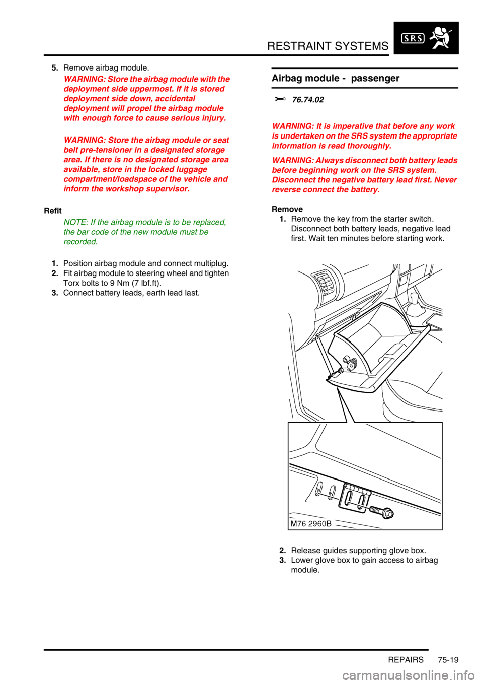
2.Release guides supporting glove box.
3.Lower glove box to gain access to airbag
module.
Page 1116 of 1672
RESTRAINT SYSTEMS
REPAIRS 75-21
Refit
CAUTION: The SRS diagnostic control unit
is a shock sensitive device and must be
handled with extreme care.
1.Position DCU to body and connect multiplug.
2.Fit and tighten DCU Torx bolts to 10 Nm (7
lbf.ft).
3.Fit centre console.
lOn manual gearbox models:
+ INTERIOR TRIM COMPONENTS,
REPAIRS, Console - centre - manual
models.
lOn automatic gearbox models:
+ INTERIOR TRIM COMPONENTS,
REPAIRS, Console - centre - automatic
models.
4.Connect battery leads, earth lead last.
Rotary coupler
$% 76.74.20
WARNING: It is imperative that before any work
is undertaken on the SRS system the appropriate
information is read thoroughly.
WARNING: Always disconnect both battery leads
before beginning work on the SRS system.
Disconnect the negative battery lead first. Never
reverse connect the battery.
Remove
1.Remove the key from the starter switch.
Disconnect both battery leads, negative lead
first. Wait ten minutes before starting work.
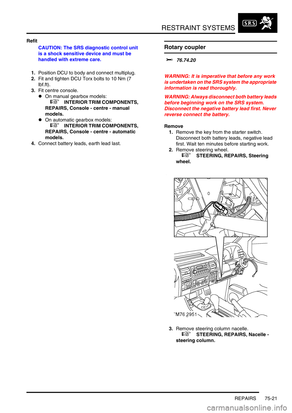
2.Remove steering wheel.
+ STEERING, REPAIRS, Steering
wheel.
3.Remove steering column nacelle.
+ STEERING, REPAIRS, Nacelle -
steering column.
Page 1127 of 1672
DOORS
76-1-4 REPAIRS
19.Remove 6 bolts securing tail door hinges to
body and, with assistance, remove tail door.
Refit
1.Support the tail door on a jack, using a block of
wood to protect the door.
2.With assistance position door. Fit securing
bolts but do not tighten at this stage.
3.Fit washer and spring clip securing check strap
to aperture.
4.Adjust position of tail door in relation to
aperture, ensuring gaps around all 4 edges
are consistent, and door closes cleanly onto
dove tail.
5.When tail door is correctly adjusted, tighten tail
door hinge bolts to 34 Nm (25 lbf.ft).
6.Feed harness and washer tube through outer
edge of door and connect harness sleeve to
door.
7.Secure harness to tail door with clips.
8.Connect washer tube to rear of wiper arm.
9.Remove tape from draw string and secure to
CHMSL wires.
10.Draw wires through tail door and connect
Lucars to CHMSL.
11.Fit CHMSL cover and secure with screws.
12.Connect multiplug of number plate lamp.
13.Connect Lucars to HRW.
14.Connect multiplug to rear wiper motor.
15.Connect multiplug to door latch.
16.Fit water shedder to door.
17.Fit tail door trim casing.
+ DOORS, REPAIRS, Trim casing - tail
door.
18.Fit spare wheel to tail door.
Glass - front or rear door
$% 76.31.01
Remove
1.Remove door trim casing.
+ DOORS, REPAIRS, Trim casing -
front door.
+ DOORS, REPAIRS, Trim casing -
rear door.
2.Carefully release water shedder from door.
3. Front door glass only: Remove exterior door
mirror.
+ EXTERIOR FITTINGS, REPAIRS,
Mirror - exterior - electric.
4.Remove inner waist seal.
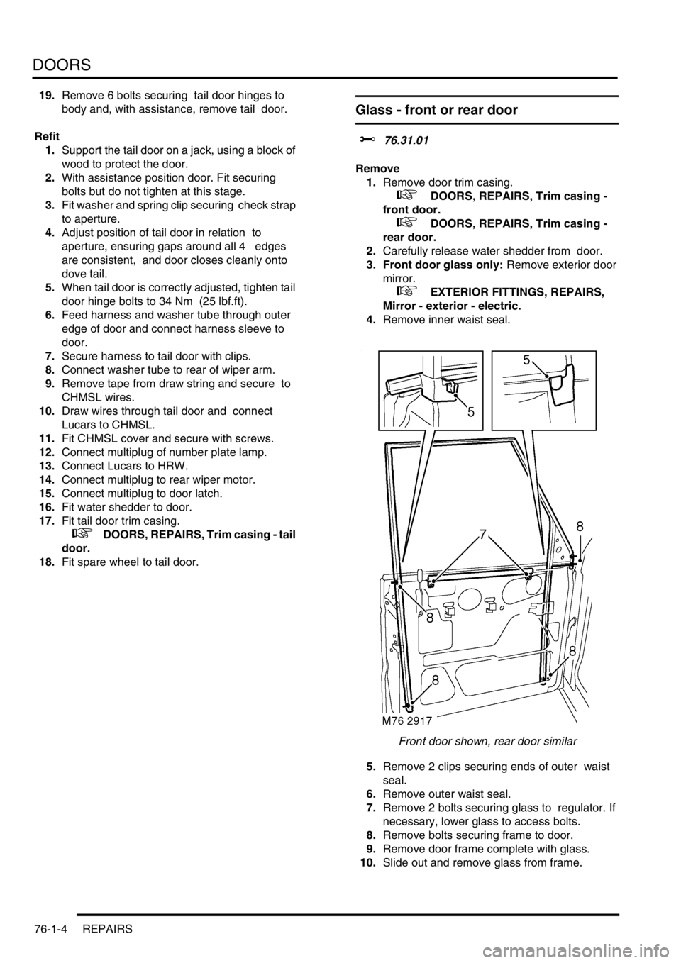
Front door shown, rear door similar
5.Remove 2 clips securing ends of outer waist
seal.
6.Remove outer waist seal.
7.Remove 2 bolts securing glass to regulator. If
necessary, lower glass to access bolts.
8.Remove bolts securing frame to door.
9.Remove door frame complete with glass.
10.Slide out and remove glass from frame.
Page 1139 of 1672
EXTERIOR FITTINGS
76-2-2 REPAIRS
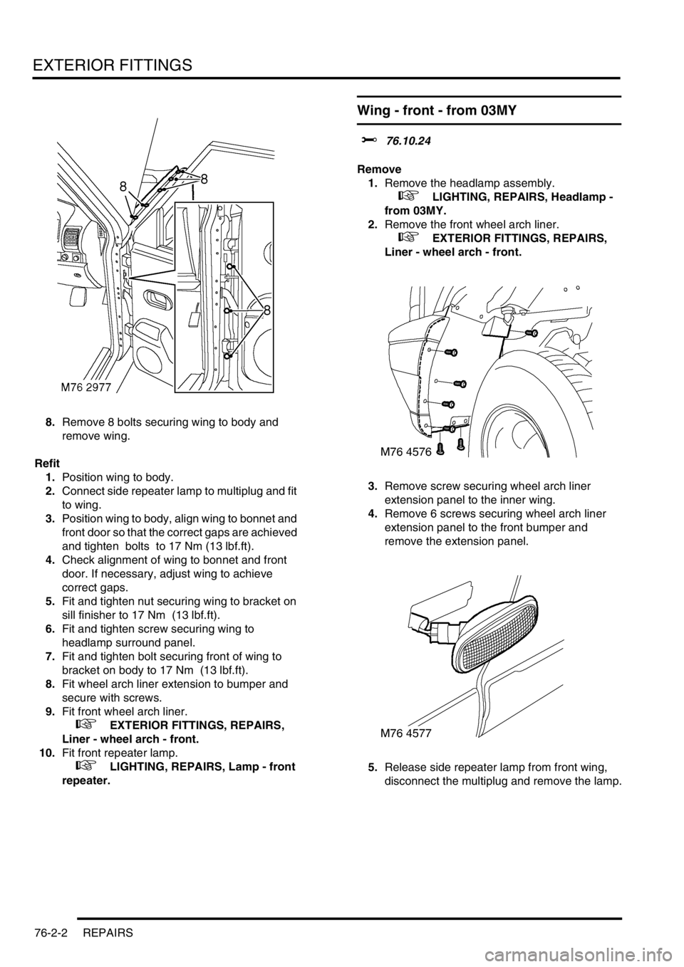
8.Remove 8 bolts securing wing to body and
remove wing.
Refit
1.Position wing to body.
2.Connect side repeater lamp to multiplug and fit
to wing.
3.Position wing to body, align wing to bonnet and
front door so that the correct gaps are achieved
and tighten bolts to 17 Nm (13 lbf.ft).
4.Check alignment of wing to bonnet and front
door. If necessary, adjust wing to achieve
correct gaps.
5.Fit and tighten nut securing wing to bracket on
sill finisher to 17 Nm (13 lbf.ft).
6.Fit and tighten screw securing wing to
headlamp surround panel.
7.Fit and tighten bolt securing front of wing to
bracket on body to 17 Nm (13 lbf.ft).
8.Fit wheel arch liner extension to bumper and
secure with screws.
9.Fit front wheel arch liner.
+ EXTERIOR FITTINGS, REPAIRS,
Liner - wheel arch - front.
10.Fit front repeater lamp.
+ LIGHTING, REPAIRS, Lamp - front
repeater.
Wing - front - from 03MY
$% 76.10.24
Remove
1.Remove the headlamp assembly.
+ LIGHTING, REPAIRS, Headlamp -
from 03MY.
2.Remove the front wheel arch liner.
+ EXTERIOR FITTINGS, REPAIRS,
Liner - wheel arch - front.
3.Remove screw securing wheel arch liner
extension panel to the inner wing.
4.Remove 6 screws securing wheel arch liner
extension panel to the front bumper and
remove the extension panel.
5.Release side repeater lamp from front wing,
disconnect the multiplug and remove the lamp.
Page 1140 of 1672
EXTERIOR FITTINGS
REPAIRS 76-2-3
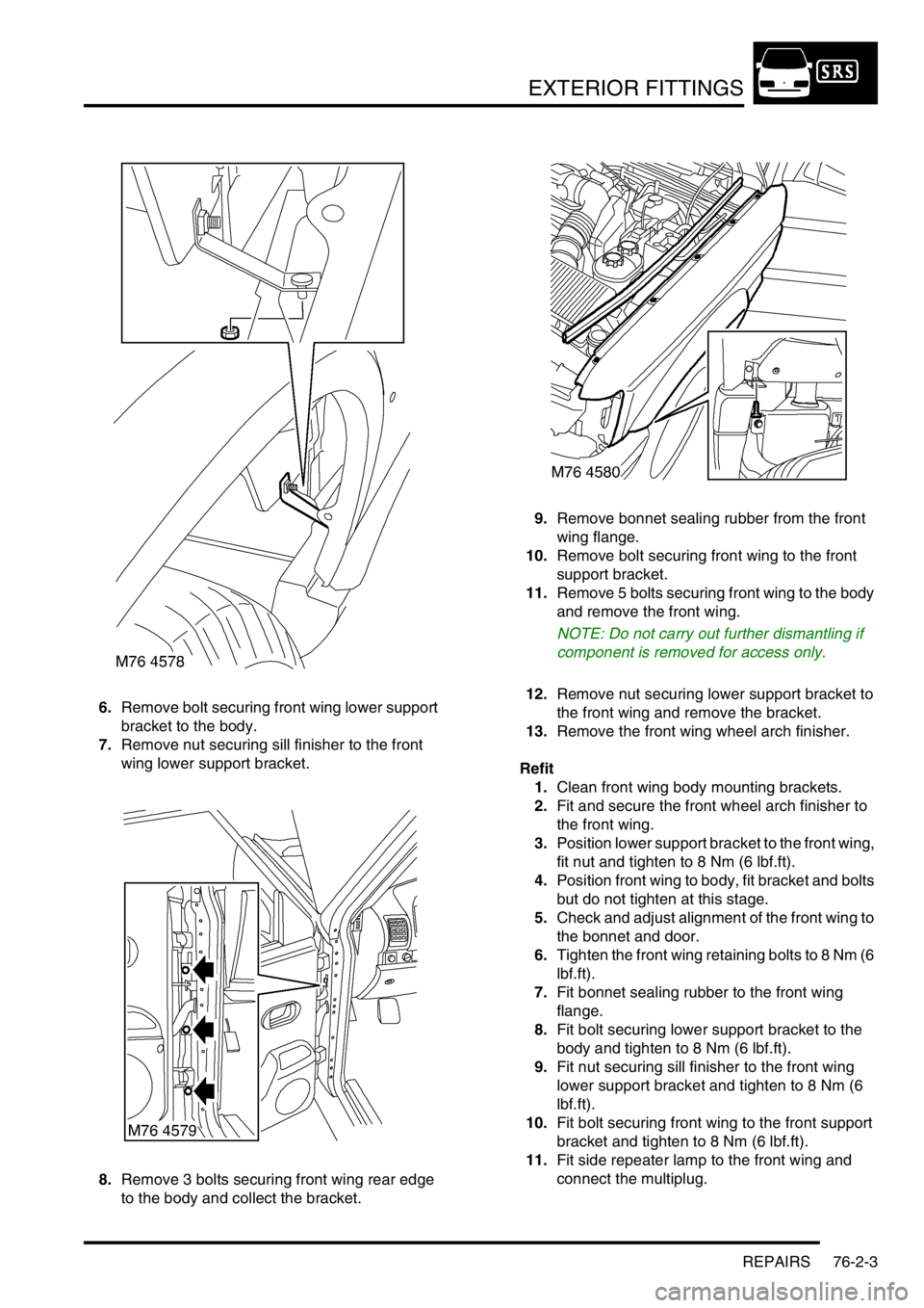
6.Remove bolt securing front wing lower support
bracket to the body.
7.Remove nut securing sill finisher to the front
wing lower support bracket.
8.Remove 3 bolts securing front wing rear edge
to the body and collect the bracket.9.Remove bonnet sealing rubber from the front
wing flange.
10.Remove bolt securing front wing to the front
support bracket.
11.Remove 5 bolts securing front wing to the body
and remove the front wing.
NOTE: Do not carry out further dismantling if
component is removed for access only.
12.Remove nut securing lower support bracket to
the front wing and remove the bracket.
13.Remove the front wing wheel arch finisher.
Refit
1.Clean front wing body mounting brackets.
2.Fit and secure the front wheel arch finisher to
the front wing.
3.Position lower support bracket to the front wing,
fit nut and tighten to 8 Nm (6 lbf.ft).
4.Position front wing to body, fit bracket and bolts
but do not tighten at this stage.
5.Check and adjust alignment of the front wing to
the bonnet and door.
6.Tighten the front wing retaining bolts to 8 Nm (6
lbf.ft).
7.Fit bonnet sealing rubber to the front wing
flange.
8.Fit bolt securing lower support bracket to the
body and tighten to 8 Nm (6 lbf.ft).
9.Fit nut securing sill finisher to the front wing
lower support bracket and tighten to 8 Nm (6
lbf.ft).
10.Fit bolt securing front wing to the front support
bracket and tighten to 8 Nm (6 lbf.ft).
11.Fit side repeater lamp to the front wing and
connect the multiplug.
Page 1141 of 1672
EXTERIOR FITTINGS
76-2-4 REPAIRS
12.Fit front wheel arch liner extension panel to the
front bumper and secure with screws.
13.Fit and tighten screw securing front wheel arch
liner extension panel to the inner wing.
14.Fit the front wheel arch liner.
+ EXTERIOR FITTINGS, REPAIRS,
Liner - wheel arch - front.
15.Fit the headlamp assembly.
+ LIGHTING, REPAIRS, Headlamp -
from 03MY.
Rear folding step
$% 76.10.41
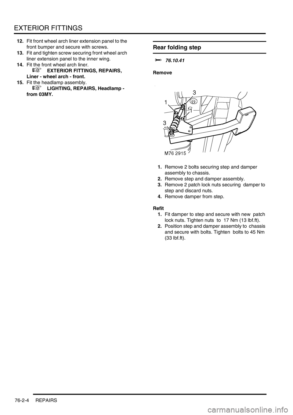
Remove
1.Remove 2 bolts securing step and damper
assembly to chassis.
2.Remove step and damper assembly.
3.Remove 2 patch lock nuts securing damper to
step and discard nuts.
4.Remove damper from step.
Refit
1.Fit damper to step and secure with new patch
lock nuts. Tighten nuts to 17 Nm (13 lbf.ft).
2.Position step and damper assembly to chassis
and secure with bolts. Tighten bolts to 45 Nm
(33 lbf.ft).
Page 1162 of 1672
INTERIOR TRIM COMPONENTS
REPAIRS 76-3-9
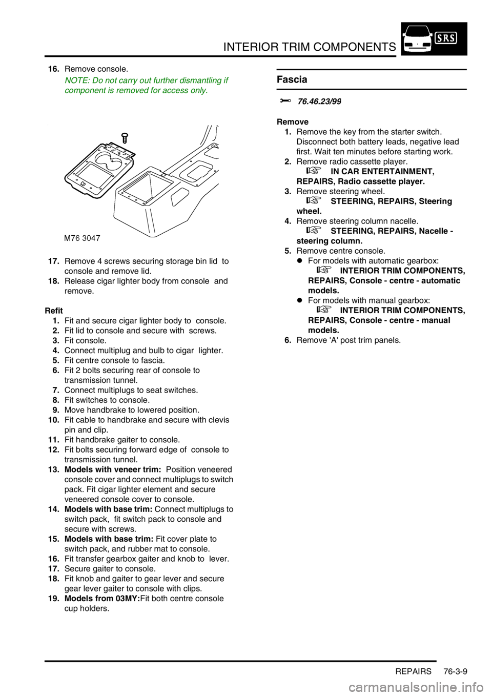
16.Remove console.
NOTE: Do not carry out further dismantling if
component is removed for access only.
17.Remove 4 screws securing storage bin lid to
console and remove lid.
18.Release cigar lighter body from console and
remove.
Refit
1.Fit and secure cigar lighter body to console.
2.Fit lid to console and secure with screws.
3.Fit console.
4.Connect multiplug and bulb to cigar lighter.
5.Fit centre console to fascia.
6.Fit 2 bolts securing rear of console to
transmission tunnel.
7.Connect multiplugs to seat switches.
8.Fit switches to console.
9.Move handbrake to lowered position.
10.Fit cable to handbrake and secure with clevis
pin and clip.
11.Fit handbrake gaiter to console.
12.Fit bolts securing forward edge of console to
transmission tunnel.
13. Models with veneer trim: Position veneered
console cover and connect multiplugs to switch
pack. Fit cigar lighter element and secure
veneered console cover to console.
14. Models with base trim: Connect multiplugs to
switch pack, fit switch pack to console and
secure with screws.
15. Models with base trim: Fit cover plate to
switch pack, and rubber mat to console.
16.Fit transfer gearbox gaiter and knob to lever.
17.Secure gaiter to console.
18.Fit knob and gaiter to gear lever and secure
gear lever gaiter to console with clips.
19. Models from 03MY:Fit both centre console
cup holders.
Fascia
$% 76.46.23/99
Remove
1.Remove the key from the starter switch.
Disconnect both battery leads, negative lead
first. Wait ten minutes before starting work.
2.Remove radio cassette player.
+ IN CAR ENTERTAINMENT,
REPAIRS, Radio cassette player.
3.Remove steering wheel.
+ STEERING, REPAIRS, Steering
wheel.
4.Remove steering column nacelle.
+ STEERING, REPAIRS, Nacelle -
steering column.
5.Remove centre console.
lFor models with automatic gearbox:
+ INTERIOR TRIM COMPONENTS,
REPAIRS, Console - centre - automatic
models.
lFor models with manual gearbox:
+ INTERIOR TRIM COMPONENTS,
REPAIRS, Console - centre - manual
models.
6.Remove 'A' post trim panels.
Page 1165 of 1672
INTERIOR TRIM COMPONENTS
76-3-12 REPAIRS
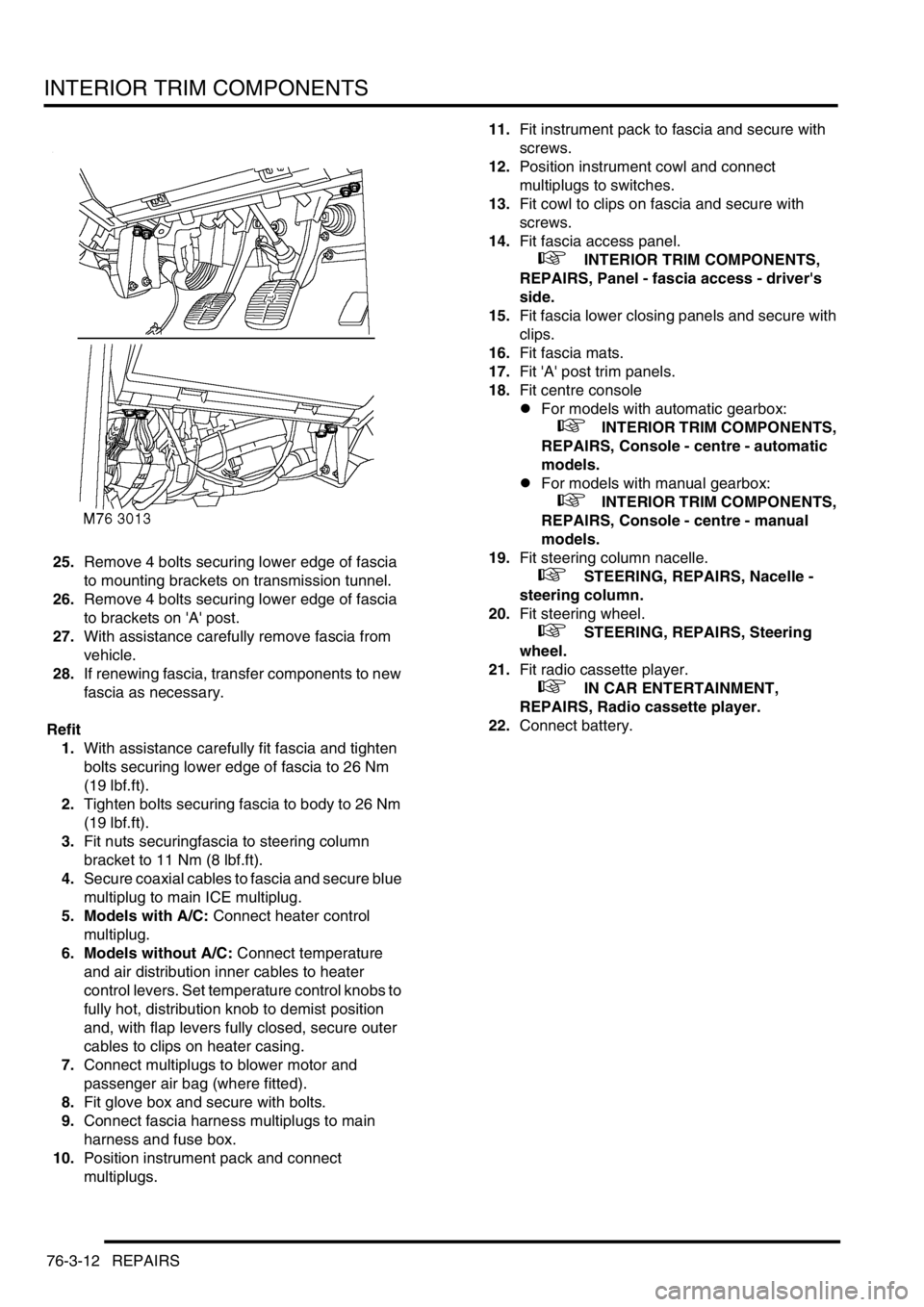
25.Remove 4 bolts securing lower edge of fascia
to mounting brackets on transmission tunnel.
26.Remove 4 bolts securing lower edge of fascia
to brackets on 'A' post.
27.With assistance carefully remove fascia from
vehicle.
28.If renewing fascia, transfer components to new
fascia as necessary.
Refit
1.With assistance carefully fit fascia and tighten
bolts securing lower edge of fascia to 26 Nm
(19 lbf.ft).
2.Tighten bolts securing fascia to body to 26 Nm
(19 lbf.ft).
3.Fit nuts securingfascia to steering column
bracket to 11 Nm (8 lbf.ft).
4.Secure coaxial cables to fascia and secure blue
multiplug to main ICE multiplug.
5. Models with A/C: Connect heater control
multiplug.
6. Models without A/C: Connect temperature
and air distribution inner cables to heater
control levers. Set temperature control knobs to
fully hot, distribution knob to demist position
and, with flap levers fully closed, secure outer
cables to clips on heater casing.
7.Connect multiplugs to blower motor and
passenger air bag (where fitted).
8.Fit glove box and secure with bolts.
9.Connect fascia harness multiplugs to main
harness and fuse box.
10.Position instrument pack and connect
multiplugs.11.Fit instrument pack to fascia and secure with
screws.
12.Position instrument cowl and connect
multiplugs to switches.
13.Fit cowl to clips on fascia and secure with
screws.
14.Fit fascia access panel.
+ INTERIOR TRIM COMPONENTS,
REPAIRS, Panel - fascia access - driver's
side.
15.Fit fascia lower closing panels and secure with
clips.
16.Fit fascia mats.
17.Fit 'A' post trim panels.
18.Fit centre console
lFor models with automatic gearbox:
+ INTERIOR TRIM COMPONENTS,
REPAIRS, Console - centre - automatic
models.
lFor models with manual gearbox:
+ INTERIOR TRIM COMPONENTS,
REPAIRS, Console - centre - manual
models.
19.Fit steering column nacelle.
+ STEERING, REPAIRS, Nacelle -
steering column.
20.Fit steering wheel.
+ STEERING, REPAIRS, Steering
wheel.
21.Fit radio cassette player.
+ IN CAR ENTERTAINMENT,
REPAIRS, Radio cassette player.
22.Connect battery.