2002 LAND ROVER DISCOVERY wheel bolts
[x] Cancel search: wheel boltsPage 1035 of 1672
REAR SUSPENSION
64-30 REPAIRS
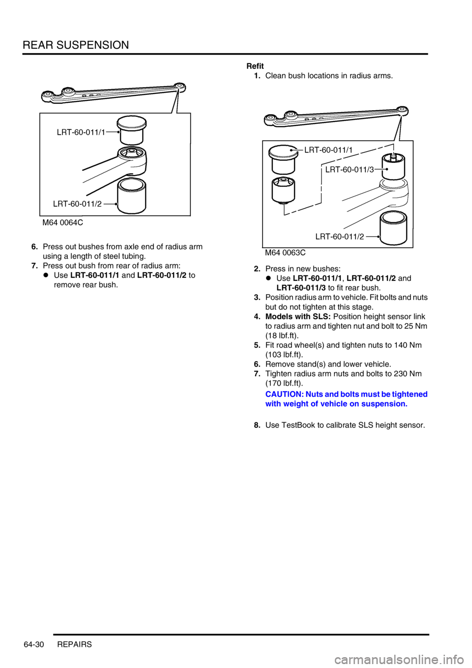
6.Press out bushes from axle end of radius arm
using a length of steel tubing.
7.Press out bush from rear of radius arm:
lUse LRT-60-011/1 and LRT-60-011/2 to
remove rear bush.Refit
1.Clean bush locations in radius arms.
2.Press in new bushes:
lUse LRT-60-011/1, LRT-60-011/2 and
LRT-60-011/3 to fit rear bush.
3.Position radius arm to vehicle. Fit bolts and nuts
but do not tighten at this stage.
4. Models with SLS: Position height sensor link
to radius arm and tighten nut and bolt to 25 Nm
(18 lbf.ft).
5.Fit road wheel(s) and tighten nuts to 140 Nm
(103 lbf.ft).
6.Remove stand(s) and lower vehicle.
7.Tighten radius arm nuts and bolts to 230 Nm
(170 lbf.ft).
CAUTION: Nuts and bolts must be tightened
with weight of vehicle on suspension.
8.Use TestBook to calibrate SLS height sensor.
Page 1051 of 1672

BRAKES
70-6 DESCRIPTION AND OPERATION
For all control functions, the ABS modulator regulates the hydraulic pressure to the brakes to control the speed of all
four wheels, either individually or in axle pairs. Operation of the ABS modulator is controlled by the Self Levelling and
Anti-lock Braking Systems (SLABS) ECU. The SLABS ECU also operates warning indications in the instrument pack
to provide the driver with status information on each function.
Brake servo assembly
The brake servo assembly provides power assistance to reduce the pedal load when braking. If the brake servo
assembly fails, the hydraulic system still functions but will require greater brake pedal effort due to the lack of vacuum
assistance.
Two integral tie bolts attach the brake servo assembly to the pedal and bracket assembly on the engine bulkhead.
The master cylinder assembly is attached to the forward ends of the tie bolts.
The brake servo assembly consists of a circular housing which contains two diaphragms, a central plate, a control
valve assembly, input and output push rods and a filter. The input push rod is connected to the brake pedal. The output
push rod locates in the primary piston of the master cylinder. A protective gaiter is installed on the control valve
assembly where it extends from the rear of the housing. A non return valve, installed in a port in the front face of the
housing, is connected to a vacuum line from the engine.
The control valve assembly consists of a valve body containing a valve, a piston, a valve spring and an input rod
spring. The valve controls a vacuum port in the valve body. The piston controls an air inlet port between the valve and
the piston. A reaction disc and a ratio disc separate the piston from the output push rod. A guide tube on the front of
the valve body is attached to the front diaphragm and supported in a bush in the central plate. A return spring locates
in the open end of the guide tube.
The two diaphragms and the central plate separate the interior of the housing into four sealed chambers. The
chambers at the front of the diaphragms are connected together through fixed passages in the valve assembly. The
chambers at the rear of the diaphragms are connected together through the interior of minor diaphragms on the tie
bolts.
Brakes off
With the brake pedal released, the piston in the control valve assembly positions the valve so that the vacuum port is
open and the two pairs of chambers are connected together. When the engine is running air is evacuated through the
vacuum line and non return valve, creating a partial vacuum in all four chambers. When the engine stops, the non
return valve closes to maintain the partial vacuum and, on V8 models, prevent fuel vapour entering the brake servo.
Page 1078 of 1672
BRAKES
REPAIRS 70-33
REPAIRS
Brake disc - front
$% 70.12.10
Brake discs must be renewed in pairs, unless
one disc requires changing before 1000 miles
(1500 km) from new.
Remove
1.Raise front of vehicle.
WARNING: Do not work on or under a
vehicle supported only by a jack. Always
support the vehicle on safety stands.
2.Remove road wheel(s).
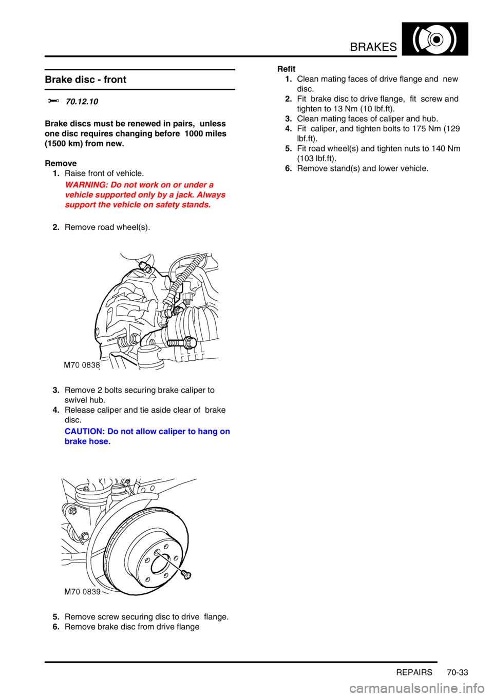
3.Remove 2 bolts securing brake caliper to
swivel hub.
4.Release caliper and tie aside clear of brake
disc.
CAUTION: Do not allow caliper to hang on
brake hose.
5.Remove screw securing disc to drive flange.
6.Remove brake disc from drive flange Refit
1.Clean mating faces of drive flange and new
disc.
2.Fit brake disc to drive flange, fit screw and
tighten to 13 Nm (10 lbf.ft).
3.Clean mating faces of caliper and hub.
4.Fit caliper, and tighten bolts to 175 Nm (129
lbf.ft).
5.Fit road wheel(s) and tighten nuts to 140 Nm
(103 lbf.ft).
6.Remove stand(s) and lower vehicle.
Page 1079 of 1672
BRAKES
70-34 REPAIRS
Brake disc - rear
$% 70.12.33
Brake discs must be renewed in pairs, unless
one disc requires changing before 1000 miles
(1500 km) from new.
Remove
1.Raise rear of vehicle.
WARNING: Do not work on or under a
vehicle supported only by a jack. Always
support the vehicle on safety stands.
2.Remove road wheel(s).
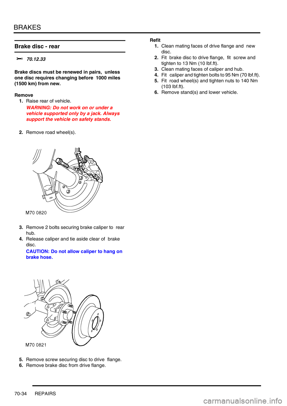
3.Remove 2 bolts securing brake caliper to rear
hub.
4.Release caliper and tie aside clear of brake
disc.
CAUTION: Do not allow caliper to hang on
brake hose.
5.Remove screw securing disc to drive flange.
6.Remove brake disc from drive flange. Refit
1.Clean mating faces of drive flange and new
disc.
2.Fit brake disc to drive flange, fit screw and
tighten to 13 Nm (10 lbf.ft).
3.Clean mating faces of caliper and hub.
4.Fit caliper and tighten bolts to 95 Nm (70 lbf.ft).
5.Fit road wheel(s) and tighten nuts to 140 Nm
(103 lbf.ft).
6.Remove stand(s) and lower vehicle.
Page 1088 of 1672
BRAKES
REPAIRS 70-43
Refit
1.Clean mating faces of alternator and vacuum
pump.
2.Fit vacuum pump to alternator and tighten
bolts to 8 Nm (6 lbf.ft).
3.Position alternator to engine and connect
multiplug.
4.Connect vacuum hose and oil drain hose to
vacuum pump and secure clips.
5.With assistance align alternator to mounting
bracket and fit but do not tighten bolt.
6.Fit bolt securing support stay to alternator and
tighten to 25 Nm (18 lbf.ft) .
7.Tighten bolt securing alternator to mounting
bracket to 45 Nm (33 lbf.ft).
8.Using new 'O' ring, connect oil supply pipe to
cylinder head and tighten to 10 Nm (7 lbf.ft).
9.Connect lead to alternator and tighten nut to 6
Nm (4.4 lbf.ft).
10.Fit auxiliary drive belt tensioner and tighten bolt
to 50 Nm (37 lbf.ft).
11.Fit auxiliary drive belt.
+ CHARGING AND STARTING,
REPAIRS, Belt - auxiliary drive.
Housing - caliper - front
$% 70.55.24
Remove
1.Raise front of vehicle, one side.
WARNING: Do not work on or under a
vehicle supported only by a jack. Always
support the vehicle on safety stands.
2.Remove road wheel(s).
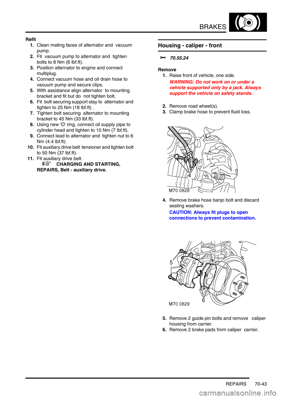
3.Clamp brake hose to prevent fluid loss.
4.Remove brake hose banjo bolt and discard
sealing washers.
CAUTION: Always fit plugs to open
connections to prevent contamination.
5.Remove 2 guide pin bolts and remove caliper
housing from carrier.
6.Remove 2 brake pads from caliper carrier.
Page 1089 of 1672
BRAKES
70-44 REPAIRS
Refit
1.Rotate disc by hand and scrape all scale and
rust from around edge of disc. Clean location
surfaces on caliper bracket.
2.Clean dust from brake parts using brake
cleaning fluid.
WARNING: Do not use compressed air to
clean brake components. Dust from friction
materials can be harmful if inhaled.
3.Fit brake pads to caliper carrier.
4.Position caliper housing to carrier, align flats on
guide pins with caliper housing.
5.Fit guide pin bolts and tighten to 30 Nm (22
lbf.ft).
6.Clean banjo bolt and fit new sealing washers.
7.Position hose to caliper and tighten banjo bolt
to 32 Nm (24 lbf.ft).
8.Remove clamp from brake hose.
9.Bleed brake system.
+ BRAKES, ADJUSTMENTS, Brake
system bleeding.
10.Fit road wheel(s) and tighten nuts to 140 Nm
(103 lbf.ft).
11.Remove stand(s) and lower vehicle.
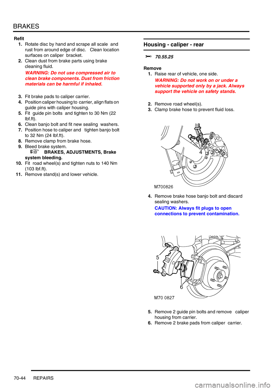
Housing - caliper - rear
$% 70.55.25
Remove
1.Raise rear of vehicle, one side.
WARNING: Do not work on or under a
vehicle supported only by a jack. Always
support the vehicle on safety stands.
2.Remove road wheel(s).
3.Clamp brake hose to prevent fluid loss.
4.Remove brake hose banjo bolt and discard
sealing washers.
CAUTION: Always fit plugs to open
connections to prevent contamination.
5.Remove 2 guide pin bolts and remove caliper
housing from carrier.
6.Remove 2 brake pads from caliper carrier.
Page 1090 of 1672
BRAKES
REPAIRS 70-45
Refit
1.Rotate disc by hand and scrape all scale and
rust from around edge of disc. Clean location
surfaces on caliper bracket.
2.Clean dust from brake parts using brake
cleaning fluid.
WARNING: Do not use compressed air to
clean brake components. Dust from friction
materials can be harmful if inhaled.
3.Fit brake pads to caliper carrier.
4.Position caliper housing to carrier, align flats on
guide pins with caliper housing.
5.Fit guide pin bolts and tighten to 30 Nm (22
lbf.ft).
6.Clean banjo bolt and fit new sealing washers.
7.Position hose to caliper and tighten banjo bolt
to 32 Nm (24 lbf.ft).
8.Remove clamp from brake hose.
9.Bleed brakes.
+ BRAKES, ADJUSTMENTS, Brake
system bleeding.
10.Fit road wheel(s) and tighten nuts to 140 Nm
(103 lbf.ft).
11.Remove stand(s) and lower vehicle.
ECU - Self levelling and anti locking
brakes (SLABS)
$% 70.65.01
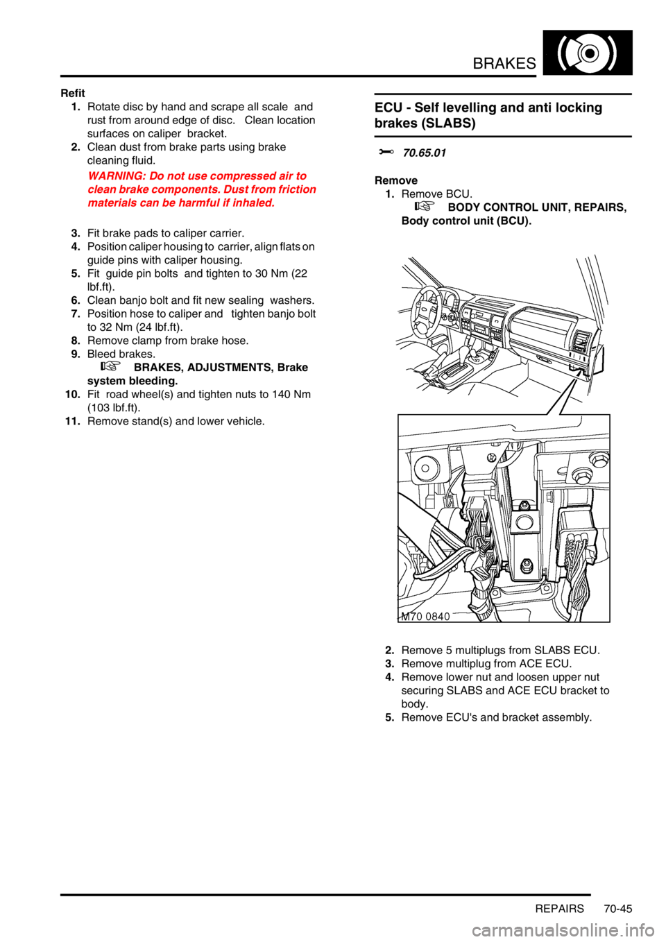
Remove
1.Remove BCU.
+ BODY CONTROL UNIT, REPAIRS,
Body control unit (BCU).
2.Remove 5 multiplugs from SLABS ECU.
3.Remove multiplug from ACE ECU.
4.Remove lower nut and loosen upper nut
securing SLABS and ACE ECU bracket to
body.
5.Remove ECU's and bracket assembly.
Page 1113 of 1672
RESTRAINT SYSTEMS
75-18 REPAIRS
Pre-tensioner - front seat belt
$% 76.73.30
WARNING: It is imperative that before any work
is undertaken on the SRS system the appropriate
information is read thoroughly.
WARNING: Always disconnect both battery leads
before beginning work on the SRS system.
Disconnect the negative battery lead first. Never
reverse connect the battery.
Remove
1.Remove the key from the starter switch.
Disconnect both battery leads, negative lead
first. Wait ten minutes before starting work.
2.Remove front seat.
+ SEATS, REPAIRS, Seat - front.
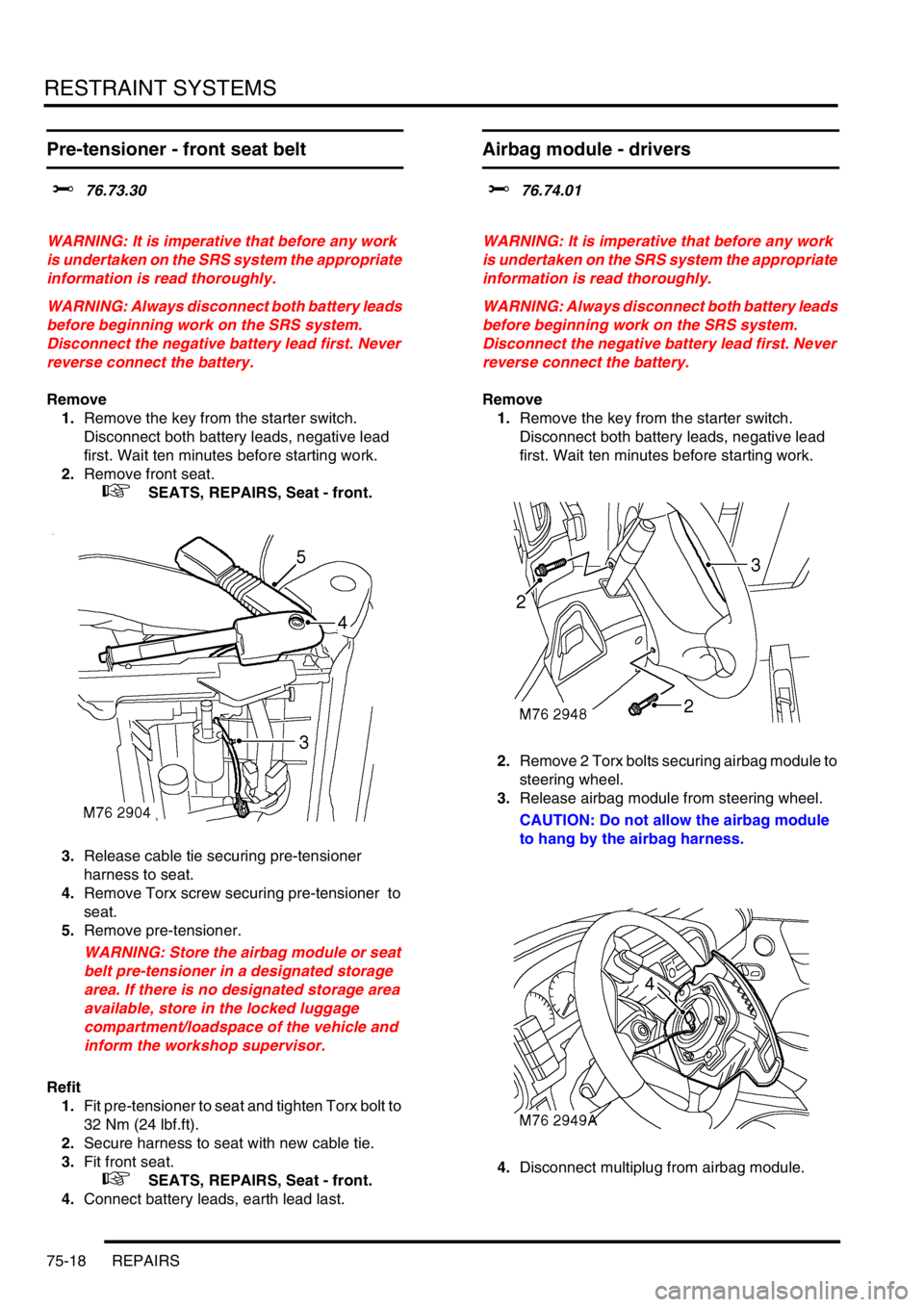
3.Release cable tie securing pre-tensioner
harness to seat.
4.Remove Torx screw securing pre-tensioner to
seat.
5.Remove pre-tensioner.
WARNING: Store the airbag module or seat
belt pre-tensioner in a designated storage
area. If there is no designated storage area
available, store in the locked luggage
compartment/loadspace of the vehicle and
inform the workshop supervisor.
Refit
1.Fit pre-tensioner to seat and tighten Torx bolt to
32 Nm (24 lbf.ft).
2.Secure harness to seat with new cable tie.
3.Fit front seat.
+ SEATS, REPAIRS, Seat - front.
4.Connect battery leads, earth lead last.
Airbag module - drivers
$% 76.74.01
WARNING: It is imperative that before any work
is undertaken on the SRS system the appropriate
information is read thoroughly.
WARNING: Always disconnect both battery leads
before beginning work on the SRS system.
Disconnect the negative battery lead first. Never
reverse connect the battery.
Remove
1.Remove the key from the starter switch.
Disconnect both battery leads, negative lead
first. Wait ten minutes before starting work.
2.Remove 2 Torx bolts securing airbag module to
steering wheel.
3.Release airbag module from steering wheel.
CAUTION: Do not allow the airbag module
to hang by the airbag harness.
4.Disconnect multiplug from airbag module.