2002 JEEP LIBERTY turn
[x] Cancel search: turnPage 1622 of 1803
COWL TRIM COVER
REMOVAL
(1) Remove the lower b-pillar trim. (Refer to 23 -
BODY/INTERIOR/B-PILLAR LOWER TRIM -
REMOVAL)
(2) Remove the cowl trim cover by pulling it away
from the a-pillar and releasing the clips.
INSTALLATION
(1) Install the cowl trim cover and seat the retain-
ing clips.
(2) Install the lower b-pillar trim. (Refer to 23 -
BODY/INTERIOR/B-PILLAR LOWER TRIM -
INSTALLATION)
DOOR SILL SCUFF PLATE
REMOVAL
(1) Using a trim stick C-4755 or equivalent, pry up
the scuff plate releasing the retaining clips.
INSTALLATION
(1) Position the scuff plate and seat the retaining
clips.
ASSIST HANDLE
REMOVAL
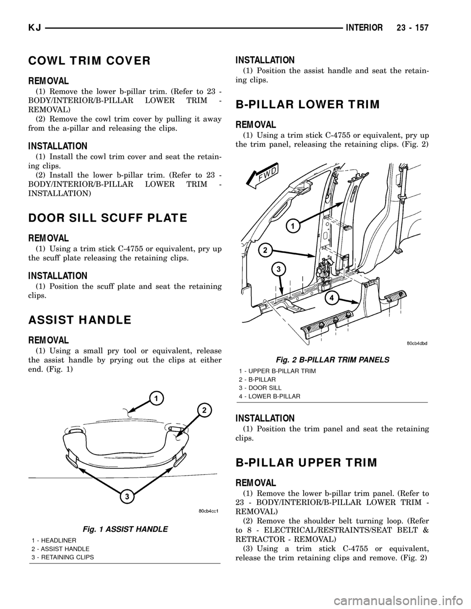
(1) Using a small pry tool or equivalent, release
the assist handle by prying out the clips at either
end. (Fig. 1)
INSTALLATION
(1) Position the assist handle and seat the retain-
ing clips.
B-PILLAR LOWER TRIM
REMOVAL
(1) Using a trim stick C-4755 or equivalent, pry up
the trim panel, releasing the retaining clips. (Fig. 2)
INSTALLATION
(1) Position the trim panel and seat the retaining
clips.
B-PILLAR UPPER TRIM
REMOVAL
(1) Remove the lower b-pillar trim panel. (Refer to
23 - BODY/INTERIOR/B-PILLAR LOWER TRIM -
REMOVAL)
(2) Remove the shoulder belt turning loop. (Refer
to 8 - ELECTRICAL/RESTRAINTS/SEAT BELT &
RETRACTOR - REMOVAL)
(3) Using a trim stick C-4755 or equivalent,
release the trim retaining clips and remove. (Fig. 2)
Fig. 1 ASSIST HANDLE
1 - HEADLINER
2 - ASSIST HANDLE
3 - RETAINING CLIPS
Fig. 2 B-PILLAR TRIM PANELS
1 - UPPER B-PILLAR TRIM
2 - B-PILLAR
3 - DOOR SILL
4 - LOWER B-PILLAR
KJINTERIOR 23 - 157
Page 1623 of 1803
INSTALLATION
(1) Position the trim panel and seat the retaining
clips.
(2) Install the seat belt turning loop. (Refer to 8 -
ELECTRICAL/RESTRAINTS/SEAT BELT &
RETRACTOR - INSTALLATION)
(3) Install the b-pillar lower trim panel. (Refer to
23 - BODY/INTERIOR/B-PILLAR LOWER TRIM -
INSTALLATION)
CARPETS AND FLOOR MATS
REMOVAL
Front Carpet
(1) Remove front seats. (Refer to 23 - BODY/
SEATS/SEAT - FRONT - REMOVAL)
(2) Remove the floor console. (Refer to 23 - BODY/
INTERIOR/FLOOR CONSOLE - REMOVAL)
(3) Remove the rear seats. (Refer to 23 - BODY/
SEATS/SEAT - REAR - REMOVAL)
(4) Remove the cowl trim panels. (Refer to 23 -
BODY/INTERIOR/COWL TRIM COVER -
REMOVAL)
(5) Remove the b-pillar lower trim. (Refer to 23 -
BODY/INTERIOR/B-PILLAR LOWER TRIM -
REMOVAL)
(6) Remove the jack assembly.
(7) Remove the carpet.
Rear Cargo Carpet
(1) Remove the rivets attaching the cargo hooks to
the floor.
(2) Remove the carpet.
INSTALLATION
Front Carpet
(1) Install the carpet.
(2) Install the jack assembly.
(3) Install the b-pillar lower trim. (Refer to 23 -
BODY/INTERIOR/B-PILLAR LOWER TRIM -
INSTALLATION)
(4) Install the cowl trim panels. (Refer to 23 -
BODY/INTERIOR/COWL TRIM COVER - INSTAL-
LATION)
(5) Install the rear seats. (Refer to 23 - BODY/
SEATS/SEAT - REAR - INSTALLATION)
(6) Install the floor console. (Refer to 23 - BODY/
INTERIOR/FLOOR CONSOLE - INSTALLATION)
(7) Install the front seats. (Refer to 23 - BODY/
SEATS/SEAT - FRONT - INSTALLATION)
Rear Cargo Carpet
(1) Install the carpet and slide under the trim pan-
els.
(2) Install new rivets securing the carpet and
cargo hooks to the floor.
SHIFT BEZEL
REMOVAL
(1) Using a trim stick C-4755 or equivalent, pry
shift bezel out of the floor console.
INSTALLATION
(1) Position the shift bezel and seat the retaining
clips into the floor console.
FLOOR CONSOLE
REMOVAL
(1) Remove the shift bezel, if equipped. (Refer to
23 - BODY/INTERIOR/SHIFT BEZEL - REMOVAL)
(2) Set park brake lever in the up position.
(3) Using a trim stick C-4755 or equivalent, dis-
connect the manual trans shifter boot, if equipped.
(4) Using a trim stick C-4755 or equivalent, dis-
connect the transfer case shifter boot, if equipped.
(5) Remove the four bolts. (Fig. 3)
(6) Lift the console at the back and remove.
INSTALLATION
(1) Position the front of the console and lower the
rear over the shifter and brake levers.
(2) Install the bolts.
(3) Install the shift boots and seat the retainer
clips.
(4) Install the shift bezel. (Refer to 23 - BODY/IN-
TERIOR/SHIFT BEZEL - INSTALLATION)
FLOOR CONSOLE LID LATCH
REMOVAL
(1) Remove the screws and remove the lid.
(2) Remove the screws attaching the lid cover and
remove the latch.
INSTALLATION
(1) Install the latch and the lid cover.
(2) Install the screws attaching the lid cover.
(3) Install the console lid onto the console and
install the screws.
23 - 158 INTERIORKJ
B-PILLAR UPPER TRIM (Continued)
Page 1629 of 1803
SEATS
TABLE OF CONTENTS
page page
HEADREST
REMOVAL............................164
INSTALLATION........................164
HEADREST SLEEVE
REMOVAL............................164
INSTALLATION........................164
SEAT - FRONT
REMOVAL............................165
INSTALLATION........................165
SEAT BACK - FRONT
REMOVAL............................166
INSTALLATION........................166
SEAT BACK RECLINER - FRONT
REMOVAL............................166
INSTALLATION........................166
SEAT BACK COVER - FRONT
REMOVAL............................166
INSTALLATION........................167
SEAT BACK CUSHION - FRONT
REMOVAL............................167
INSTALLATION........................167
SEAT CUSHION - FRONT
REMOVAL............................167
INSTALLATION........................167
SEAT CUSHION COVER - FRONT
REMOVAL............................167
INSTALLATION........................167
SEAT CUSHION SIDE SHIELDS
REMOVAL............................167
INSTALLATION........................167MANUAL SEAT RISER
REMOVAL............................167
INSTALLATION........................168
SEAT TRACK
REMOVAL............................168
INSTALLATION........................168
SEAT - REAR
REMOVAL............................168
INSTALLATION........................168
SEAT BACK - REAR
REMOVAL............................168
INSTALLATION........................168
SEAT BACK COVER - REAR
REMOVAL............................169
INSTALLATION........................169
SEAT BACK CUSHION - REAR
REMOVAL............................170
INSTALLATION........................170
FOLDING REAR SEAT BACK LATCH / LOCK
REMOVAL............................170
INSTALLATION........................170
REAR SEAT BACK LATCH STRIKER
REMOVAL............................170
INSTALLATION........................171
SEAT BACK FRAME - REAR
REMOVAL............................171
INSTALLATION........................171
SEAT CUSHION - REAR
REMOVAL............................171
INSTALLATION........................171
HEADREST
REMOVAL
(1) Depress head restraint release button and lift
head restraint to full up position.
(2) Using a small flat blade, depress tab on right
side head restraint release button and using your
hand, simultaneously press tab on left side head
restraint release button and pull head restraint up to
separate from seat back.
INSTALLATION
(1) Position head restraint in seat back, press tab
on left side head restraint release button and push
down head restraint to secure.
HEADREST SLEEVE
REMOVAL
(1) Remove the headrest. (Refer to 23 - BODY/
SEATS/HEADREST - REMOVAL)
(2) Remove the headrest sleeve cover.
(3) Rotate head restraint sleeve 1/4 turn counter-
clockwise to release retaining tab.
(4) Pull sleeve from seat back frame.
INSTALLATION
(1) Position sleeve in seat back frame.
(2) Rotate head restraint sleeve 1/4 turn clockwise
to engage retaining tab.
(3) Install the headrest sleeve cover.
(4) Install the headrest. (Refer to 23 - BODY/
SEATS/HEADREST - INSTALLATION)
23 - 164 SEATSKJ
Page 1658 of 1803
DIAGNOSIS AND TESTING - HEATER
PERFORMANCE
Before performing the following tests, refer to Cool-
ing for the procedures to check the radiator coolant
level, serpentine drive belt tension, radiator air flow
and the radiator fan operation. Also be certain that
the accessory vacuum supply line is connected at the
engine intake manifold.
MAXIMUM HEATER OUTPUT
Engine coolant is delivered to the heater core
through two heater hoses. With the engine idling atnormal operating temperature, set the temperature
control knob in the full hot position, the mode control
switch knob in the floor heat position, and the blower
motor switch knob in the highest speed position.
Using a test thermometer, check the temperature of
the air being discharged at the HVAC housing floor
outlets. Compare the test thermometer reading to the
Temperature Reference chart.
Temperature Reference
Ambient Air Temperature15.5É C
(60É F)21.1É C
(70É F)26.6É C
(80É F)32.2É C
(90É F)
Minimum Air Temperature at
Floor Outlet52.2É C
(126É F)56.1É C
(133É F)59.4É C
(139É F)62.2É C
(144É F)
If the floor outlet air temperature is too low, refer
to Cooling to check the engine coolant temperature
specifications. Both of the heater hoses should be hot
to the touch. The coolant return heater hose should
be slightly cooler than the coolant supply heater
hose. If the return hose is much cooler than the sup-
ply hose, locate and repair the engine coolant flow
obstruction in the cooling system. Refer to Cooling
for the procedures.
OBSTRUCTED COOLANT FLOW Possible loca-
tions or causes of obstructed coolant flow:
²Pinched or kinked heater hoses.
²Improper heater hose routing.
²Plugged heater hoses or supply and return ports
at the cooling system connections.
²A plugged heater core.
If proper coolant flow through the cooling system is
verified, and heater outlet air temperature is still
low, a mechanical problem may exist.
MECHANICAL PROBLEMS Possible locations or
causes of insufficient heat:
²An obstructed cowl air intake.
²Obstructed heater system outlets.
²A blend door not functioning properly.
TEMPERATURE CONTROL
If the heater outlet air temperature cannot be
adjusted with the temperature control knob on theA/C Heater control panel, the following could require
service:
²The A/C Heater control.
²The blend door actuator.
²The blend door.
²Improper engine coolant temperature.
DIAGNOSIS AND TESTING - VACUUM SYSTEM
Vacuum control is used to operate the mode doors
in the heater-only and a/c heater housings. Testing of
the heater-only and A/C Heater mode control switch
operation will determine if the vacuum, electrical,
and mechanical controls are functioning. However, it
is possible that a vacuum control system that oper-
ates perfectly at engine idle (high engine vacuum)
may not function properly at high engine speeds or
loads (low engine vacuum). This can be caused by
leaks in the vacuum system, or a faulty vacuum
check valve.
A vacuum system test will help to identify the
source of poor vacuum system performance or vac-
uum system leaks. Before starting this test, stop the
engine and make certain that the problem is not a
disconnected vacuum supply tube at the engine
intake manifold vacuum tap or at the vacuum reser-
voir.
24 - 6 HEATING & AIR CONDITIONINGKJ
HEATING & AIR CONDITIONING (Continued)
Page 1659 of 1803
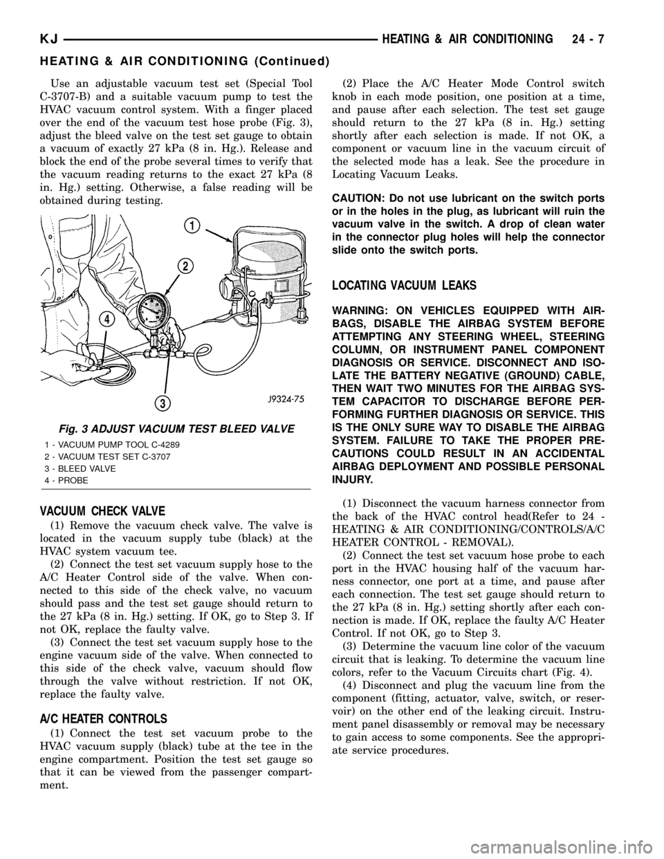
Use an adjustable vacuum test set (Special Tool
C-3707-B) and a suitable vacuum pump to test the
HVAC vacuum control system. With a finger placed
over the end of the vacuum test hose probe (Fig. 3),
adjust the bleed valve on the test set gauge to obtain
a vacuum of exactly 27 kPa (8 in. Hg.). Release and
block the end of the probe several times to verify that
the vacuum reading returns to the exact 27 kPa (8
in. Hg.) setting. Otherwise, a false reading will be
obtained during testing.
VACUUM CHECK VALVE
(1) Remove the vacuum check valve. The valve is
located in the vacuum supply tube (black) at the
HVAC system vacuum tee.
(2) Connect the test set vacuum supply hose to the
A/C Heater Control side of the valve. When con-
nected to this side of the check valve, no vacuum
should pass and the test set gauge should return to
the 27 kPa (8 in. Hg.) setting. If OK, go to Step 3. If
not OK, replace the faulty valve.
(3) Connect the test set vacuum supply hose to the
engine vacuum side of the valve. When connected to
this side of the check valve, vacuum should flow
through the valve without restriction. If not OK,
replace the faulty valve.
A/C HEATER CONTROLS
(1) Connect the test set vacuum probe to the
HVAC vacuum supply (black) tube at the tee in the
engine compartment. Position the test set gauge so
that it can be viewed from the passenger compart-
ment.(2) Place the A/C Heater Mode Control switch
knob in each mode position, one position at a time,
and pause after each selection. The test set gauge
should return to the 27 kPa (8 in. Hg.) setting
shortly after each selection is made. If not OK, a
component or vacuum line in the vacuum circuit of
the selected mode has a leak. See the procedure in
Locating Vacuum Leaks.
CAUTION: Do not use lubricant on the switch ports
or in the holes in the plug, as lubricant will ruin the
vacuum valve in the switch. A drop of clean water
in the connector plug holes will help the connector
slide onto the switch ports.
LOCATING VACUUM LEAKS
WARNING: ON VEHICLES EQUIPPED WITH AIR-
BAGS, DISABLE THE AIRBAG SYSTEM BEFORE
ATTEMPTING ANY STEERING WHEEL, STEERING
COLUMN, OR INSTRUMENT PANEL COMPONENT
DIAGNOSIS OR SERVICE. DISCONNECT AND ISO-
LATE THE BATTERY NEGATIVE (GROUND) CABLE,
THEN WAIT TWO MINUTES FOR THE AIRBAG SYS-
TEM CAPACITOR TO DISCHARGE BEFORE PER-
FORMING FURTHER DIAGNOSIS OR SERVICE. THIS
IS THE ONLY SURE WAY TO DISABLE THE AIRBAG
SYSTEM. FAILURE TO TAKE THE PROPER PRE-
CAUTIONS COULD RESULT IN AN ACCIDENTAL
AIRBAG DEPLOYMENT AND POSSIBLE PERSONAL
INJURY.
(1) Disconnect the vacuum harness connector from
the back of the HVAC control head(Refer to 24 -
HEATING & AIR CONDITIONING/CONTROLS/A/C
HEATER CONTROL - REMOVAL).
(2) Connect the test set vacuum hose probe to each
port in the HVAC housing half of the vacuum har-
ness connector, one port at a time, and pause after
each connection. The test set gauge should return to
the 27 kPa (8 in. Hg.) setting shortly after each con-
nection is made. If OK, replace the faulty A/C Heater
Control. If not OK, go to Step 3.
(3) Determine the vacuum line color of the vacuum
circuit that is leaking. To determine the vacuum line
colors, refer to the Vacuum Circuits chart (Fig. 4).
(4) Disconnect and plug the vacuum line from the
component (fitting, actuator, valve, switch, or reser-
voir) on the other end of the leaking circuit. Instru-
ment panel disassembly or removal may be necessary
to gain access to some components. See the appropri-
ate service procedures.
Fig. 3 ADJUST VACUUM TEST BLEED VALVE
1 - VACUUM PUMP TOOL C-4289
2 - VACUUM TEST SET C-3707
3 - BLEED VALVE
4 - PROBE
KJHEATING & AIR CONDITIONING 24 - 7
HEATING & AIR CONDITIONING (Continued)
Page 1661 of 1803
(5) Connect the test set hose or probe to the open
end of the leaking circuit. The test set gauge should
return to the 27 kPa (8 in. Hg.) setting shortly after
each connection is made. If OK, replace the faulty
disconnected component. If not OK, go to Step 6.
(6)
To locate a leak in a vacuum line, leave one end
of the line plugged and connect the test set hose or
probe to the other end of the line. Run your fingers
slowly along the line while watching the test set gauge.
The vacuum reading will fluctuate when your fingers
contact the source of the leak. To repair the vacuum
line, cut out the leaking section of the line. Then, insert
the loose ends of the line into a suitable length of 3 mil-
limeter (0.125 inch) inside diameter rubber hose.
STANDARD PROCEDURE - DIODE
REPLACEMENT
(1) Disconnect the battery negative cable and iso-
late it.
(2) Locate the diode in the harness, and remove
the protective covering.
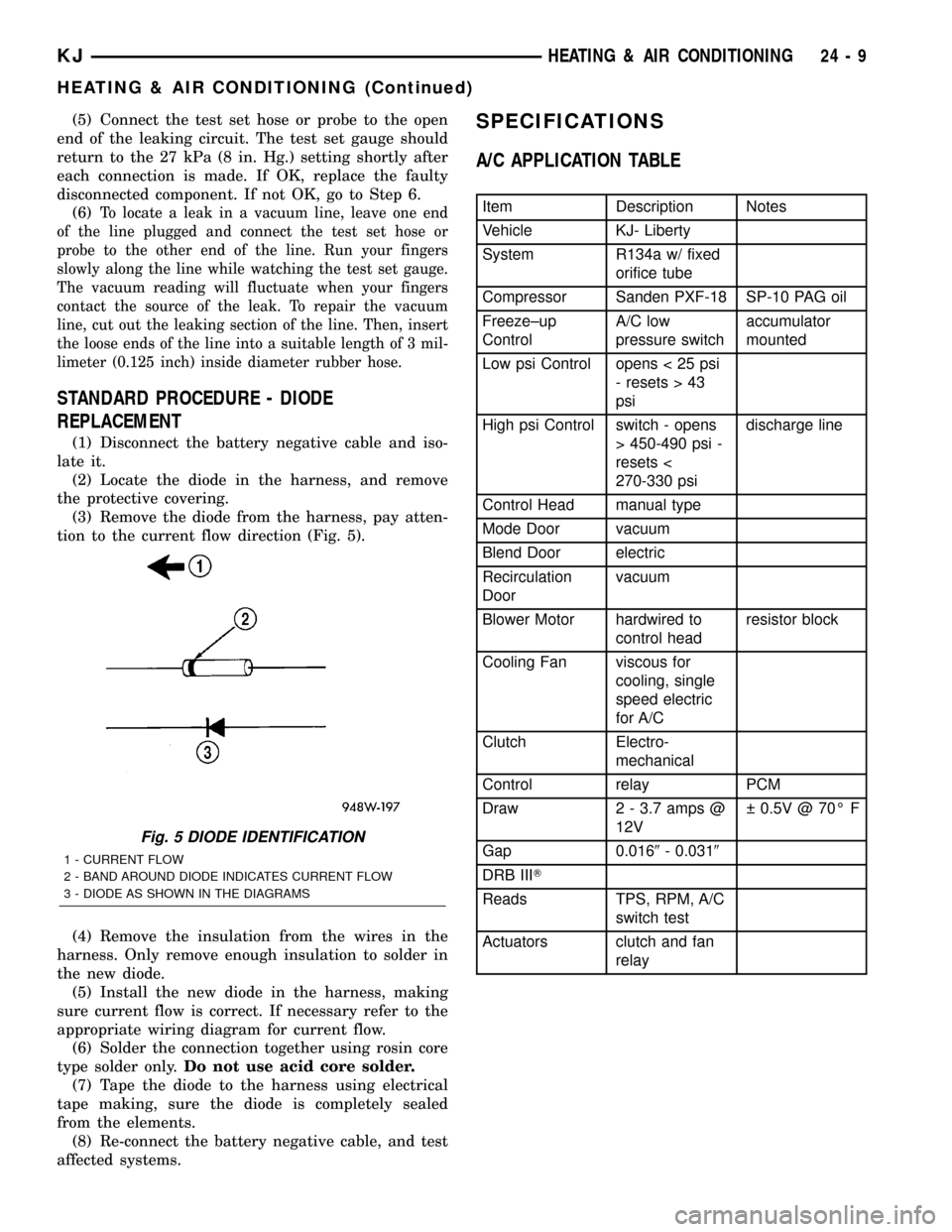
(3) Remove the diode from the harness, pay atten-
tion to the current flow direction (Fig. 5).
(4) Remove the insulation from the wires in the
harness. Only remove enough insulation to solder in
the new diode.
(5) Install the new diode in the harness, making
sure current flow is correct. If necessary refer to the
appropriate wiring diagram for current flow.
(6) Solder the connection together using rosin core
type solder only.Do not use acid core solder.
(7) Tape the diode to the harness using electrical
tape making, sure the diode is completely sealed
from the elements.
(8) Re-connect the battery negative cable, and test
affected systems.
SPECIFICATIONS
A/C APPLICATION TABLE
Item Description Notes
Vehicle KJ- Liberty
System R134a w/ fixed
orifice tube
Compressor Sanden PXF-18 SP-10 PAG oil
Freeze±up
ControlA/C low
pressure switchaccumulator
mounted
Low psi Control opens < 25 psi
- resets > 43
psi
High psi Control switch - opens
> 450-490 psi -
resets <
270-330 psidischarge line
Control Head manual type
Mode Door vacuum
Blend Door electric
Recirculation
Doorvacuum
Blower Motor hardwired to
control headresistor block
Cooling Fan viscous for
cooling, single
speed electric
for A/C
Clutch Electro-
mechanical
Control relay PCM
Draw 2 - 3.7 amps @
12V 0.5V @ 70É F
Gap 0.0169- 0.0319
DRB IIIT
Reads TPS, RPM, A/C
switch test
Actuators clutch and fan
relay
Fig. 5 DIODE IDENTIFICATION
1 - CURRENT FLOW
2 - BAND AROUND DIODE INDICATES CURRENT FLOW
3 - DIODE AS SHOWN IN THE DIAGRAMS
KJHEATING & AIR CONDITIONING 24 - 9
HEATING & AIR CONDITIONING (Continued)
Page 1664 of 1803
A/C COMPRESSOR CLUTCH
DESCRIPTION - 3.7L and 2.4L
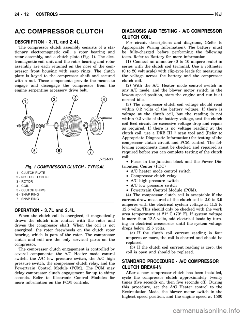
The compressor clutch assembly consists of a sta-
tionary electromagnetic coil, a rotor bearing and
rotor assembly, and a clutch plate (Fig. 1). The elec-
tromagnetic coil unit and the rotor bearing and rotor
assembly are each retained on the nose of the com-
pressor front housing with snap rings. The clutch
plate is keyed to the compressor shaft and secured
with a nut. These components provide the means to
engage and disengage the compressor from the
engine serpentine accessory drive belt.
OPERATION - 3.7L and 2.4L
When the clutch coil is energized, it magnetically
draws the clutch into contact with the rotor and
drives the compressor shaft. When the coil is not
energized, the rotor freewheels on the clutch rotor
bearing, which is part of the rotor. The compressor
clutch and coil are the only serviced parts on the
compressor.
The compressor clutch engagement is controlled by
several components: the A/C Heater mode control
switch, the A/C low pressure switch, the A/C high
pressure switch, the compressor clutch relay, and the
Powertrain Control Module (PCM). The PCM may
delay compressor clutch engagement for up to thirty
seconds. Refer to Electronic Control Modules for
more information on the PCM controls.
DIAGNOSIS AND TESTING - A/C COMPRESSOR
CLUTCH COIL
For circuit descriptions and diagrams, (Refer to
Appropriate Wiring Information). The battery must
be fully-charged before performing the following
tests. Refer to Battery for more information.
(1) Connect an ammeter (0 to 10 ampere scale) in
series with the clutch coil terminal. Use a voltmeter
(0 to 20 volt scale) with clip-type leads for measuring
the voltage across the battery and the compressor
clutch coil.
(2) With the A/C Heater mode control switch in
any A/C mode, and the blower motor switch in the
lowest speed position, start the engine and run it at
normal idle.
(3) The compressor clutch coil voltage should read
within 0.2 volts of the battery voltage. If there is
voltage at the clutch coil, but the reading is not
within 0.2 volts of the battery voltage, test the clutch
coil feed circuit for excessive voltage drop and repair
as required. If there is no voltage reading at the
clutch coil, use a DRB IIItscan tool and (Refer to
Appropriate Diagnostic Information) for testing of the
compressor clutch circuit and PCM control. The fol-
lowing components must be checked and repaired as
required before you can complete testing of the clutch
coil:
²Fuses in the junction block and the Power Dis-
tribution Center (PDC)
²A/C heater mode control switch
²Compressor clutch relay
²A/C high pressure switch
²A/C low pressure switch
²Powertrain Control Module (PCM).
(4) The compressor clutch coil is acceptable if the
current draw measured at the clutch coil is 2.0 to 3.9
amperes with the electrical system voltage at 11.5 to
12.5 volts. This should only be checked with the work
area temperature at 21É C (70É F). If system voltage
is more than 12.5 volts, add electrical loads by turn-
ing on electrical accessories until the system voltage
drops below 12.5 volts.
(a) If the clutch coil current reading is four
amperes or more, the coil is shorted and should be
replaced.
(b) If the clutch coil current reading is zero, the
coil is open and should be replaced.
STANDARD PROCEDURE - A/C COMPRESSOR
CLUTCH BREAK-IN
After a new compressor clutch has been installed,
cycle the compressor clutch approximately twenty
times (five seconds on, then five seconds off). During
this procedure, set the A/C Heater control to the
Recirculation Mode, the blower motor switch in the
highest speed position, and the engine speed at 1500
Fig. 1 COMPRESSOR CLUTCH - TYPICAL
1 - CLUTCH PLATE
2 - NOT USED ON KJ
3 - ROTOR
4 - COIL
5 - CLUTCH SHIMS
6 - SNAP RING
7 - SNAP RING
24 - 12 CONTROLSKJ
Page 1666 of 1803
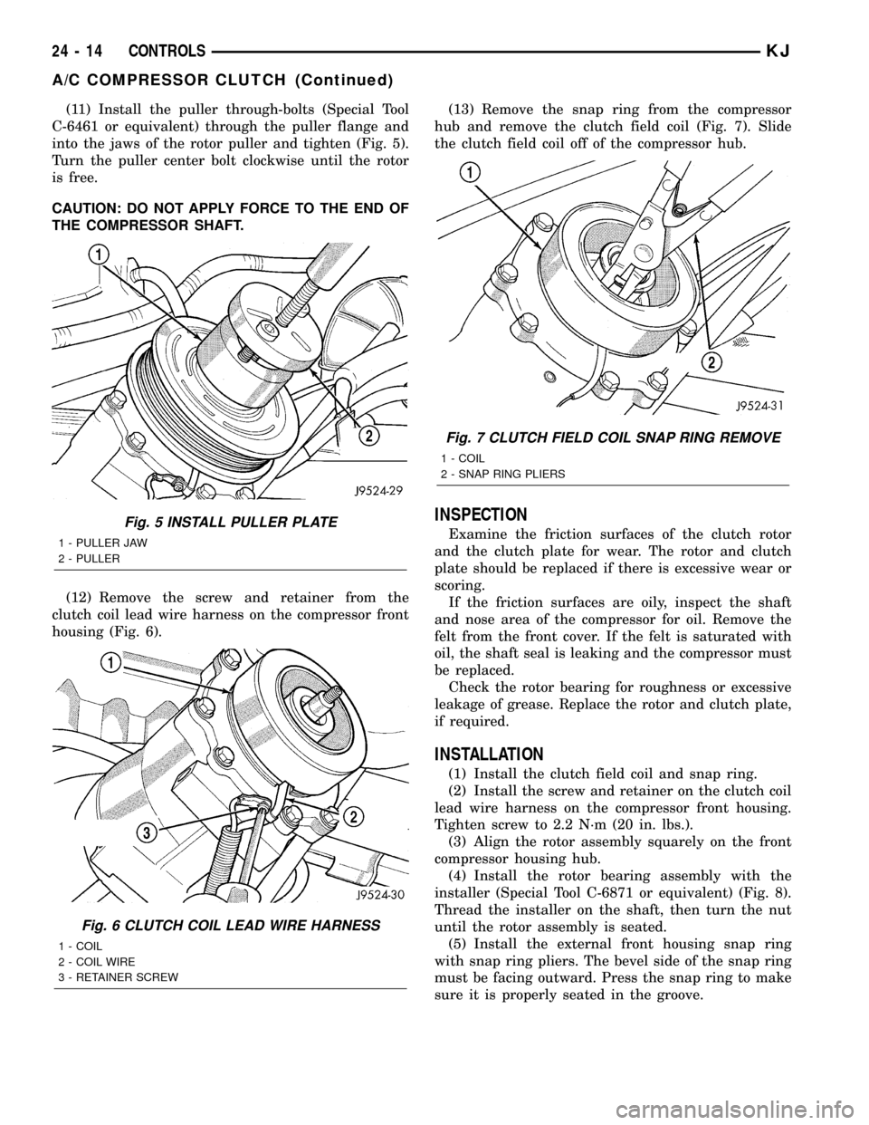
(11) Install the puller through-bolts (Special Tool
C-6461 or equivalent) through the puller flange and
into the jaws of the rotor puller and tighten (Fig. 5).
Turn the puller center bolt clockwise until the rotor
is free.
CAUTION: DO NOT APPLY FORCE TO THE END OF
THE COMPRESSOR SHAFT.
(12) Remove the screw and retainer from the
clutch coil lead wire harness on the compressor front
housing (Fig. 6).(13) Remove the snap ring from the compressor
hub and remove the clutch field coil (Fig. 7). Slide
the clutch field coil off of the compressor hub.
INSPECTION
Examine the friction surfaces of the clutch rotor
and the clutch plate for wear. The rotor and clutch
plate should be replaced if there is excessive wear or
scoring.
If the friction surfaces are oily, inspect the shaft
and nose area of the compressor for oil. Remove the
felt from the front cover. If the felt is saturated with
oil, the shaft seal is leaking and the compressor must
be replaced.
Check the rotor bearing for roughness or excessive
leakage of grease. Replace the rotor and clutch plate,
if required.
INSTALLATION
(1) Install the clutch field coil and snap ring.
(2) Install the screw and retainer on the clutch coil
lead wire harness on the compressor front housing.
Tighten screw to 2.2 N´m (20 in. lbs.).
(3) Align the rotor assembly squarely on the front
compressor housing hub.
(4) Install the rotor bearing assembly with the
installer (Special Tool C-6871 or equivalent) (Fig. 8).
Thread the installer on the shaft, then turn the nut
until the rotor assembly is seated.
(5) Install the external front housing snap ring
with snap ring pliers. The bevel side of the snap ring
must be facing outward. Press the snap ring to make
sure it is properly seated in the groove.
Fig. 5 INSTALL PULLER PLATE
1 - PULLER JAW
2 - PULLER
Fig. 6 CLUTCH COIL LEAD WIRE HARNESS
1 - COIL
2 - COIL WIRE
3 - RETAINER SCREW
Fig. 7 CLUTCH FIELD COIL SNAP RING REMOVE
1 - COIL
2 - SNAP RING PLIERS
24 - 14 CONTROLSKJ
A/C COMPRESSOR CLUTCH (Continued)