2002 JEEP LIBERTY compression ratio
[x] Cancel search: compression ratioPage 40 of 1803

UPPER BALL JOINT
REMOVAL
(1) Raise and support the vehicle.
(2) Support the rear axle with a hydraulic jack.
(3) Remove the ball joint pinch bolt from the top of
the axle. (Fig. 7)
(4) Seperate the ball joint arm assembly from the
differential housing by prying upwards.
INSTALLATION
(1)Raise the rear axle with a hydraulic jack to align
the ball joint with the differential housing bracket.
(2) Insert the ball joint into the differential hous-
ing bracket.
(3) Install the ball joint pinch bolt and tighten to
95 N´m (70 ft. lbs.). (Fig. 7).
(4) Remove the supports and lower the vehicle.
UPPER CONTROL ARM
DESCRIPTION - UPPER SUSPENSION ARM,
BUSHINGS, AND BALL JOINT
The suspension arm uses vertical spool bushings to
isolate road noise. The suspension arm is bolted
through bushings to cage nuts in the body and a ball
joint to the top of the differential housing.
OPERATION - UPPER SUSPENSION ARM,
BUSHINGS, AND BALL JOINT
The upper suspension arm provides fore/aft and
lateral location of the rear axle. The suspension arm
travel is limited through the use of jounce bumpers
in compression and shock absorbers in rebound.
REMOVAL
(1) Raise and support the vehicle.
(2) Support the rear axle with a hydraulic jack.
(3) Remove the ball joint pinch bolt from the top of
the differential housing bracket (Fig. 7).
(4) Remove partial nuts from the heat shield in
order to lower the shield down enough to get the
proper clearence to remove the right side bolt from
the body.
(5) Remove the upper suspension arm mounting
bolts from the body and remove the arm (Fig. 8).
(6) Remove the support bracket mounting bolts if
needed. (Fig. 9)
Fig. 7 BALL JOINT PINCH BOLT
1 - UPPER BALL JOINT
2 - PINCH BOLTFig. 8 UPPER CONTROL ARM
1 - BODY MOUNTS
2 - UPPER BALL JOINT
3 - STABILIZER BAR
4 - UPPER CONTROL ARM
5 - LOWER CONTROL ARM
Fig. 9 BALL JOINT BRACKET
1 - UPPER BALL JOINT
2 - SUPPORT BRACKET BOLTS
2 - 20 REARKJ
Page 396 of 1803
3.7L
The Camshaft Position Sensor (CMP) on the 3.7L
V-6 engine is bolted to the front/top of the right cyl-
inder head.
(1) Clean out machined hole in cylinder head.
(2) Apply a small amount of engine oil to sensor
o-ring.
(3) Install sensor into cylinder head with a slight
rocking and twisting action.
CAUTION: Before tightening sensor mounting bolt,
be sure sensor is completely flush to cylinder head.
If sensor is not flush, damage to sensor mounting
tang may result.
(4) Install mounting bolt and tighten. Refer to
torque specifications.
(5) Connect electrical connector to sensor.
IGNITION COIL
DESCRIPTION
2.4L
The coil assembly consists of 2 different coils
molded together. The assembly is mounted to the top
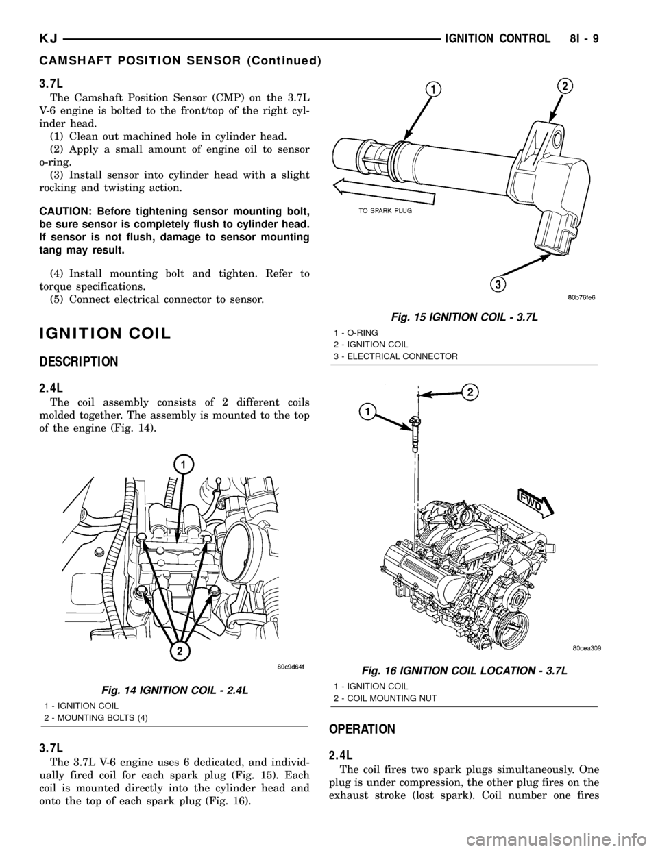
of the engine (Fig. 14).
3.7L
The 3.7L V-6 engine uses 6 dedicated, and individ-
ually fired coil for each spark plug (Fig. 15). Each
coil is mounted directly into the cylinder head and
onto the top of each spark plug (Fig. 16).
OPERATION
2.4L
The coil fires two spark plugs simultaneously. One
plug is under compression, the other plug fires on the
exhaust stroke (lost spark). Coil number one fires
Fig. 14 IGNITION COIL - 2.4L
1 - IGNITION COIL
2 - MOUNTING BOLTS (4)
Fig. 15 IGNITION COIL - 3.7L
1 - O-RING
2 - IGNITION COIL
3 - ELECTRICAL CONNECTOR
Fig. 16 IGNITION COIL LOCATION - 3.7L
1 - IGNITION COIL
2 - COIL MOUNTING NUT
KJIGNITION CONTROL 8I - 9
CAMSHAFT POSITION SENSOR (Continued)
Page 1216 of 1803
ENGINE - 3.7L
TABLE OF CONTENTS
page page
ENGINE - 3.7L
DESCRIPTION..........................3
DIAGNOSIS AND TESTING
DIAGNOSIS AND TESTING - ENGINE
DIAGNOSIS - INTRODUCTION............4
DIAGNOSIS AND TESTING - ENGINE
DIAGNOSIS - PERFORMANCE............4
DIAGNOSIS AND TESTING - ENGINE
DIAGNOSIS - MECHANICAL..............6
DIAGNOSIS AND TESTING - ENGINE
DIAGNOSIS - LUBRICATION..............7
DIAGNOSIS AND TESTING - CYLINDER
COMPRESSION PRESSURE..............8
DIAGNOSIS AND TESTING - CYLINDER
COMBUSTION PRESSURE LEAKAGE.......8
STANDARD PROCEDURE
STANDARD PROCEDURE - ENGINE
GASKET SURFACE PREPARATION.........9
STANDARD PROCEDURE - REPAIR
DAMAGED OR WORN THREADS..........9
STANDARD PROCEDURE - ENGINE CORE
AND OIL GALLERY PLUGS..............10
REMOVAL.............................10
INSTALLATION.........................11
SPECIFICATIONS
TORQUE............................12
3.7L ENGINE.........................12
SPECIAL TOOLS
3.7L ENGINE.........................15
AIR CLEANER ELEMENT
REMOVAL - 3.7L........................19
INSTALLATION - 3.7L....................19
CYLINDER HEAD - LEFT
DESCRIPTION - VALVE GUIDES...........19
DIAGNOSIS AND TESTING
DIAGNOSIS AND TESTING - HYDRAULIC
LASH ADJUSTER.....................19
DIAGNOSIS AND TESTING - CYLINDER
HEAD GASKET.......................19
REMOVAL.............................20
CLEANING............................22
INSTALLATION.........................22
CAMSHAFT(S)
DESCRIPTION.........................23
REMOVAL.............................24
INSTALLATION.........................25
CYLINDER HEAD COVER(S)
DESCRIPTION.........................25
REMOVAL.............................25INSTALLATION.........................26
INTAKE/EXHAUST VALVES & SEATS
DESCRIPTION.........................26
STANDARD PROCEDURE - REFACING......26
REMOVAL.............................27
INSTALLATION.........................28
ROCKER ARM
DESCRIPTION.........................29
VALVE GUIDE SEALS
DESCRIPTION.........................29
VALVE SPRINGS
DESCRIPTION.........................29
REMOVAL.............................29
INSTALLATION.........................29
CYLINDER HEAD - RIGHT
DESCRIPTION
DESCRIPTION - CYLINDER HEAD........30
DESCRIPTION - VALVE GUIDES..........30
DESCRIPTION........................30
DIAGNOSIS AND TESTING
DIAGNOSIS AND TESTING - HYDRAULIC
LASH ADJUSTER.....................30
DIAGNOSIS AND TESTING - CYLINDER
HEAD GASKET.......................30
REMOVAL.............................31
CLEANING............................31
INSPECTION..........................32
INSTALLATION.........................32
CAMSHAFT(S)
DESCRIPTION.........................33
REMOVAL.............................33
INSTALLATION.........................33
CYLINDER HEAD COVER(S)
REMOVAL.............................34
INSTALLATION.........................34
INTAKE/EXHAUST VALVES & SEATS
STANDARD PROCEDURE - REFACING......34
REMOVAL.............................35
INSTALLATION.........................36
ROCKER ARM
DESCRIPTION.........................37
REMOVAL.............................37
INSTALLATION.........................37
VALVE GUIDE SEALS
DESCRIPTION.........................38
VALVE SPRINGS
DESCRIPTION.........................38
REMOVAL.............................38
INSTALLATION.........................38
KJENGINE - 3.7L 9 - 1
Page 1220 of 1803
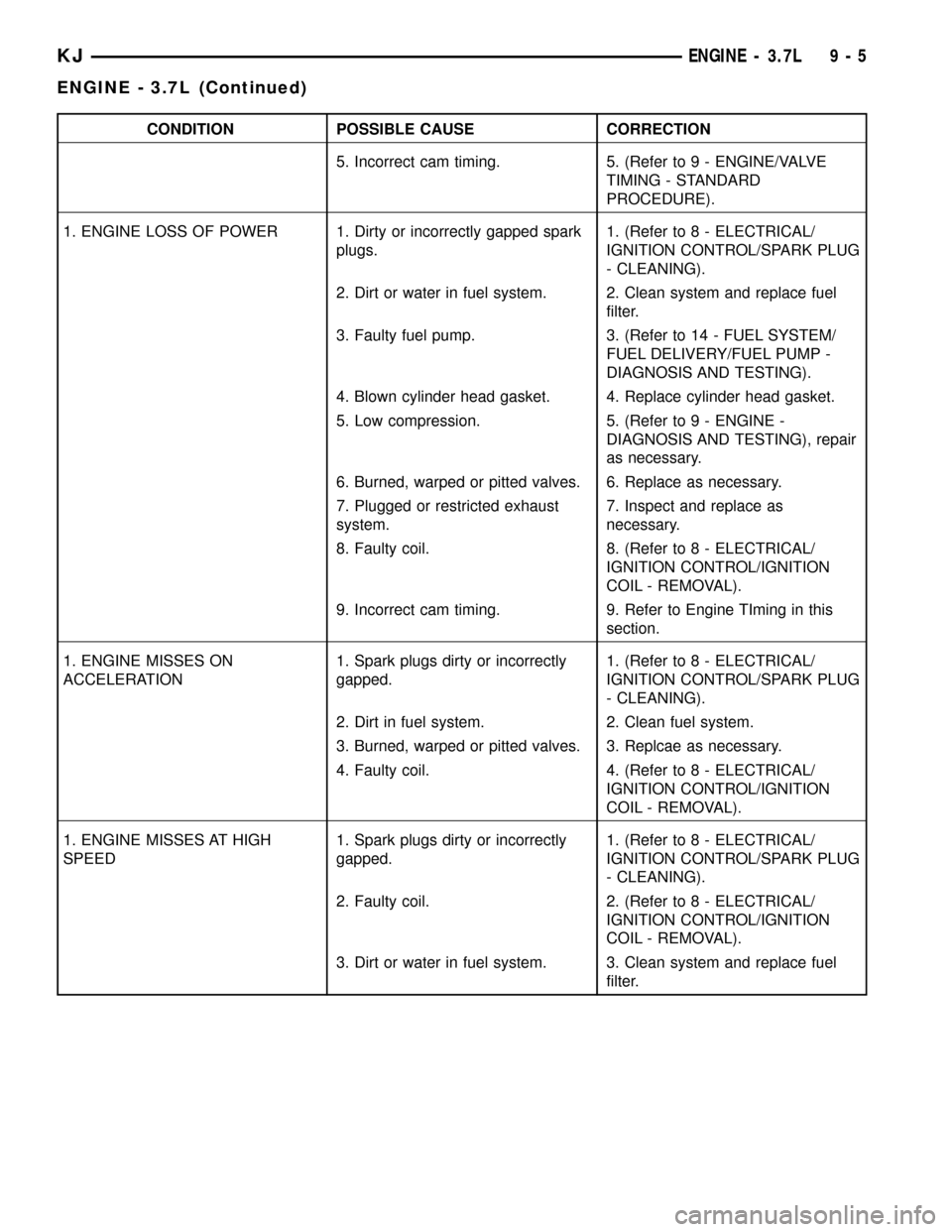
CONDITION POSSIBLE CAUSE CORRECTION
5. Incorrect cam timing. 5. (Refer to 9 - ENGINE/VALVE
TIMING - STANDARD
PROCEDURE).
1. ENGINE LOSS OF POWER 1. Dirty or incorrectly gapped spark
plugs.1. (Refer to 8 - ELECTRICAL/
IGNITION CONTROL/SPARK PLUG
- CLEANING).
2. Dirt or water in fuel system. 2. Clean system and replace fuel
filter.
3. Faulty fuel pump. 3. (Refer to 14 - FUEL SYSTEM/
FUEL DELIVERY/FUEL PUMP -
DIAGNOSIS AND TESTING).
4. Blown cylinder head gasket. 4. Replace cylinder head gasket.
5. Low compression. 5. (Refer to 9 - ENGINE -
DIAGNOSIS AND TESTING), repair
as necessary.
6. Burned, warped or pitted valves. 6. Replace as necessary.
7. Plugged or restricted exhaust
system.7. Inspect and replace as
necessary.
8. Faulty coil. 8. (Refer to 8 - ELECTRICAL/
IGNITION CONTROL/IGNITION
COIL - REMOVAL).
9. Incorrect cam timing. 9. Refer to Engine TIming in this
section.
1. ENGINE MISSES ON
ACCELERATION1. Spark plugs dirty or incorrectly
gapped.1. (Refer to 8 - ELECTRICAL/
IGNITION CONTROL/SPARK PLUG
- CLEANING).
2. Dirt in fuel system. 2. Clean fuel system.
3. Burned, warped or pitted valves. 3. Replcae as necessary.
4. Faulty coil. 4. (Refer to 8 - ELECTRICAL/
IGNITION CONTROL/IGNITION
COIL - REMOVAL).
1. ENGINE MISSES AT HIGH
SPEED1. Spark plugs dirty or incorrectly
gapped.1. (Refer to 8 - ELECTRICAL/
IGNITION CONTROL/SPARK PLUG
- CLEANING).
2. Faulty coil. 2. (Refer to 8 - ELECTRICAL/
IGNITION CONTROL/IGNITION
COIL - REMOVAL).
3. Dirt or water in fuel system. 3. Clean system and replace fuel
filter.
KJENGINE - 3.7L 9 - 5
ENGINE - 3.7L (Continued)
Page 1227 of 1803
(35) Install the mechanical cooling fan.
(36) Install the fan shroud with the electric fan
assembly.
(37) Install the radiator core support bracket.
(38) Install the air cleaner assembly.
(39) Refill the engine cooling system.
(40) Install the hood.
(41) Check and fill engine oil.
(42) Connect the battery negative cable.
(43) Start the engine and check for leaks.
SPECIFICATIONS
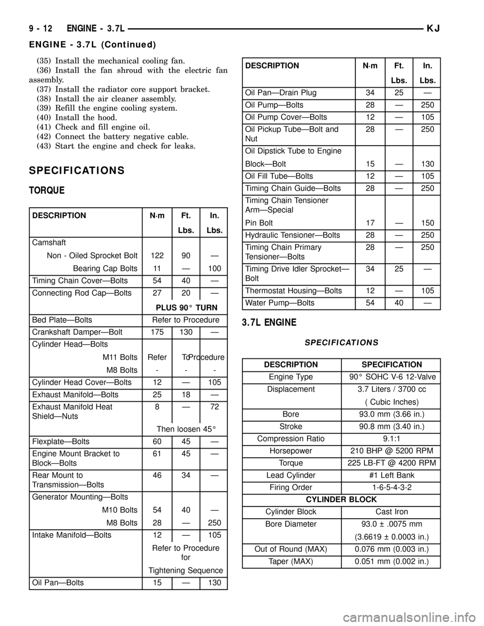
TORQUE
DESCRIPTION N´m Ft. In.
Lbs. Lbs.
Camshaft
Non - Oiled Sprocket Bolt 122 90 Ð
Bearing Cap Bolts 11 Ð 100
Timing Chain CoverÐBolts 54 40 Ð
Connecting Rod CapÐBolts 27 20 Ð
PLUS 90É TURN
Bed PlateÐBolts Refer to Procedure
Crankshaft DamperÐBolt 175 130 Ð
Cylinder HeadÐBolts
M11 Bolts Refer ToProcedure
M8 Bolts - - -
Cylinder Head CoverÐBolts 12 Ð 105
Exhaust ManifoldÐBolts 25 18 Ð
Exhaust Manifold Heat
ShieldÐNuts8Ð72
Then loosen 45É
FlexplateÐBolts 60 45 Ð
Engine Mount Bracket to
BlockÐBolts61 45 Ð
Rear Mount to
TransmissionÐBolts46 34 Ð
Generator MountingÐBolts
M10 Bolts 54 40 Ð
M8 Bolts 28 Ð 250
Intake ManifoldÐBolts 12 Ð 105
Refer to Procedure
for
Tightening Sequence
Oil PanÐBolts 15 Ð 130
DESCRIPTION N´m Ft. In.
Lbs. Lbs.
Oil PanÐDrain Plug 34 25 Ð
Oil PumpÐBolts 28 Ð 250
Oil Pump CoverÐBolts 12 Ð 105
Oil Pickup TubeÐBolt and
Nut28 Ð 250
Oil Dipstick Tube to Engine
BlockÐBolt 15 Ð 130
Oil Fill TubeÐBolts 12 Ð 105
Timing Chain GuideÐBolts 28 Ð 250
Timing Chain Tensioner
ArmÐSpecial
Pin Bolt 17 Ð 150
Hydraulic TensionerÐBolts 28 Ð 250
Timing Chain Primary
TensionerÐBolts28 Ð 250
Timing Drive Idler SprocketÐ
Bolt34 25 Ð
Thermostat HousingÐBolts 12 Ð 105
Water PumpÐBolts 54 40 Ð
3.7L ENGINE
SPECIFICATIONS
DESCRIPTION SPECIFICATION
Engine Type 90É SOHC V-6 12-Valve
Displacement 3.7 Liters / 3700 cc
( Cubic Inches)
Bore 93.0 mm (3.66 in.)
Stroke 90.8 mm (3.40 in.)
Compression Ratio 9.1:1
Horsepower 210 BHP @ 5200 RPM
Torque 225 LB-FT @ 4200 RPM
Lead Cylinder #1 Left Bank
Firing Order 1-6-5-4-3-2
CYLINDER BLOCK
Cylinder Block Cast Iron
Bore Diameter 93.0 .0075 mm
(3.6619 0.0003 in.)
Out of Round (MAX) 0.076 mm (0.003 in.)
Taper (MAX) 0.051 mm (0.002 in.)
9 - 12 ENGINE - 3.7LKJ
ENGINE - 3.7L (Continued)
Page 1235 of 1803
Possible indications of the cylinder head gasket
leaking between adjacent cylinders are:
²Loss of engine power
²Engine misfiring
²Poor fuel economy
Possible indications of the cylinder head gasket
leaking between a cylinder and an adjacent water
jacket are:
²Engine overheating
²Loss of coolant
²Excessive steam (white smoke) emitting from
exhaust
²Coolant foaming
CYLINDER-TO-CYLINDER LEAKAGE TEST
To determine if an engine cylinder head gasket is
leaking between adjacent cylinders, follow the proce-
dures in Cylinder Compression Pressure Test (Refer
to 9 - ENGINE - DIAGNOSIS AND TESTING). An
engine cylinder head gasket leaking between adja-
cent cylinders will result in approximately a 50±70%
reduction in compression pressure.
CYLINDER-TO-WATER JACKET LEAKAGE TEST
WARNING: USE EXTREME CAUTION WHEN THE
ENGINE IS OPERATING WITH COOLANT PRES-
SURE CAP REMOVED.
VISUAL TEST METHOD
With the engine cool, remove the coolant pressure
cap. Start the engine and allow it to warm up until
thermostat opens.
If a large combustion/compression pressure leak
exists, bubbles will be visible in the coolant.
COOLING SYSTEM TESTER METHOD
WARNING: WITH COOLING SYSTEM TESTER IN
PLACE, PRESSURE WILL BUILD UP FAST. EXCES-
SIVE PRESSURE BUILT UP, BY CONTINUOUS
ENGINE OPERATION, MUST BE RELEASED TO A
SAFE PRESSURE POINT. NEVER PERMIT PRES-
SURE TO EXCEED 138 kPa (20 psi).
Install Cooling System Tester 7700 or equivalent to
pressure cap neck. Start the engine and observe the
tester's pressure gauge. If gauge pulsates with every
power stroke of a cylinder a combustion pressure
leak is evident.
CHEMICAL TEST METHOD
Combustion leaks into the cooling system can also
be checked by using Bloc-Chek Kit C-3685-A or
equivalent. Perform test following the procedures
supplied with the tool kit.
REMOVAL
(1) Disconnect the negative cable from the battery.
(2) Raise the vehicle on a hoist.
(3) Disconnect the exhaust pipe at the left side
exhaust manifold.
(4) Drain the engine coolant. Refer to COOLING
SYSTEM.
(5) Lower the vehicle.
(6) Remove the intake manifold. Refer to proce-
dure in this section.
(7) Remove the cylinder head cover. Refer to proce-
dure in this section.
(8) Remove the fan shroud and fan blade assembly.
Refer to COOLING SYSTEM.
(9) Remove accessory drive belt. Refer to COOL-
ING SYSTEM.
(10) Remove the power steering pump and set
aside.
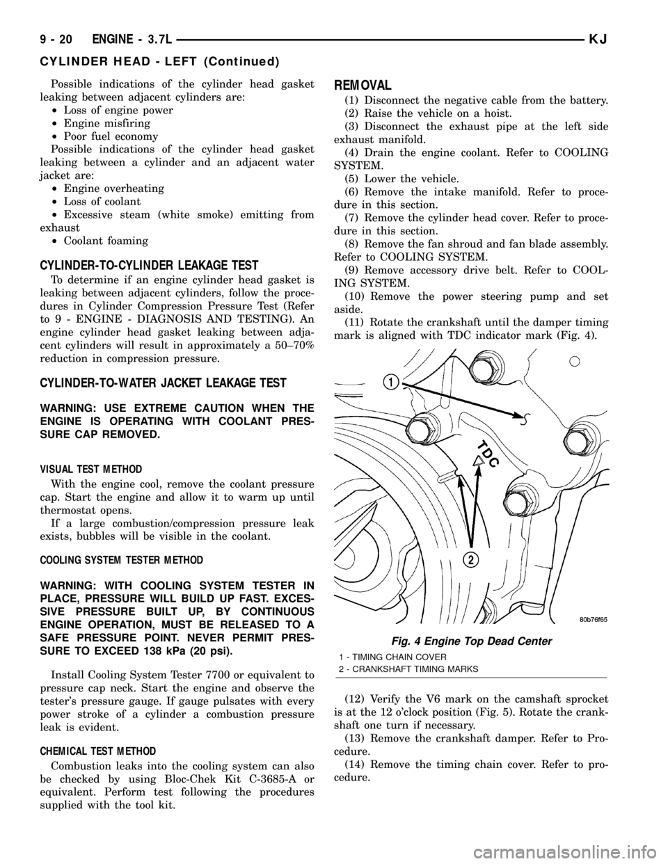
(11) Rotate the crankshaft until the damper timing
mark is aligned with TDC indicator mark (Fig. 4).
(12) Verify the V6 mark on the camshaft sprocket
is at the 12 o'clock position (Fig. 5). Rotate the crank-
shaft one turn if necessary.
(13) Remove the crankshaft damper. Refer to Pro-
cedure.
(14) Remove the timing chain cover. Refer to pro-
cedure.
Fig. 4 Engine Top Dead Center
1 - TIMING CHAIN COVER
2 - CRANKSHAFT TIMING MARKS
9 - 20 ENGINE - 3.7LKJ
CYLINDER HEAD - LEFT (Continued)
Page 1246 of 1803
VISUAL TEST METHOD
With the engine cool, remove the coolant pressure
cap. Start the engine and allow it to warm up until
thermostat opens.
If a large combustion/compression pressure leak
exists, bubbles will be visible in the coolant.
COOLING SYSTEM TESTER METHOD
WARNING: WITH COOLING SYSTEM TESTER IN
PLACE, PRESSURE WILL BUILD UP FAST. EXCES-
SIVE PRESSURE BUILT UP, BY CONTINUOUS
ENGINE OPERATION, MUST BE RELEASED TO A
SAFE PRESSURE POINT. NEVER PERMIT PRES-
SURE TO EXCEED 138 kPa (20 psi).
Install Cooling System Tester 7700 or equivalent to
pressure cap neck. Start the engine and observe the
tester's pressure gauge. If gauge pulsates with every
power stroke of a cylinder a combustion pressure
leak is evident.
CHEMICAL TEST METHOD
Combustion leaks into the cooling system can also
be checked by using Bloc-Chek Kit C-3685-A or
equivalent. Perform test following the procedures
supplied with the tool kit.
REMOVAL
(1) Disconnect battery negative cable.
(2) Raise the vehicle on a hoist.
(3) Disconnect the exhaust pipe at the right side
exhaust manifold.
(4) Drain the engine coolant. Refer to COOLING
SYSTEM.
(5) Lower the vehicle.
(6) Remove the intake manifold. Refer to proce-
dure.
(7) Remove the cylinder head cover. Refer to proce-
dure.
(8) Remove the fan shroud. Refer to COOLING
SYSTEM.
(9) Remove oil fill housing from cylinder head.
(10) Remove accessory drive belt. Refer to COOL-
ING SYSTEM.
(11) Rotate the crankshaft until the damper timing
mark is aligned with TDC indicator mark.
(12) Verify the V6 mark on the camshaft sprocket
is at the 12 o'clock position. Rotate the crankshaft
one turn if necessary.
(13) Remove the crankshaft damper. Refer to pro-
cedure.
(14) Remove the timing chain cover. Refer to pro-
cedure.
(15) Lock the secondary timing chains to the idler
sprocket using Special Tool 8429 Timing Chain Hold-
ing Fixture.NOTE: Mark the secondary timing chain prior to
removal to aid in installation.
(16) Mark the secondary timing chain, one link on
each side of the V6 mark on the camshaft drive gear.
(17) Remove the right side secondary chain ten-
sioner. Refer to Timing Chain and Sprockets in this
section.
(18) Remove the cylinder head access plug.
(19) Remove the right side secondary chain guide.
Refer to Timing Chain and Sprockets in this section.
CAUTION: The nut on the right side camshaft
sprocket should not be removed for any reason, as
the sprocket and camshaft sensor target wheel is
serviced as an assembly. If the nut was removed
retorque nut to 5 N´m (44 in. lbs.).
(20) Remove the retaining bolt and the camshaft
drive gear.
CAUTION: Do not allow the engine to rotate. severe
damage to the valve train can occur.
CAUTION: Do not overlook the four smaller bolts at
the front of the cylinder head. Do not attempt to
remove the cylinder head without removing these
four bolts.
CAUTION: Do not hold or pry on the camshaft tar-
get wheel for any reason. A damaged target wheel
can result in a vehicle no start condition.
NOTE: The cylinder head is attached to the cylinder
block with twelve bolts.
(21) Remove the cylinder head retaining bolts.
(22) Remove the cylinder head and gasket. Discard
the gasket.
CAUTION: Do not lay the cylinder head on its gas-
ket sealing surface, do to the design of the cylinder
head gasket any distortion to the cylinder head
sealing surface may prevent the gasket from prop-
erly sealing resulting in leaks.
CLEANING
To ensure engine gasket sealing, proper surface
preparation must be performed, especially with the
use of aluminum engine components (Fig. 22). (Refer
to 9 - ENGINE - STANDARD PROCEDURE)
KJENGINE - 3.7L 9 - 31
CYLINDER HEAD - RIGHT (Continued)
Page 1298 of 1803
ENGINE
TABLE OF CONTENTS
page page
ENGINE - 2.4L
DESCRIPTION..........................3
DIAGNOSIS AND TESTING
DIAGNOSIS AND TESTING - CYLINDER
COMBUSTION PRESSURE LEAKAGE
TEST................................3
DIAGNOSIS AND TESTING - CYLINDER
COMPRESSION PRESSURE TEST.........3
DIAGNOSIS AND TESTING - ENGINE OIL
LEAK INSPECTION.....................4
DIAGNOSIS AND TESTING - ENGINE.......5
DIAGNOSIS AND TESTING - ENGINE
DIAGNOSIS - PERFORMANCE............5
DIAGNOSIS AND TESTING - ENGINE
MECHANICAL.........................7
STANDARD PROCEDURE
STANDARD PROCEDURE - ENGINE CORE
AND OIL GALLERY PLUGS...............9
STANDARD PROCEDURE - REPAIR OF
DAMAGED OR WORN THREADS..........9
STANDARD PROCEDURE - HYDROSTATIC
LOCKED ENGINE......................9
STANDARD PROCEDURE - FORM-IN-
PLACE GASKETS AND SEALERS.........10
STANDARD PROCEDURE - ENGINE
GASKET SURFACE PREPARATION........11
STANDARD PROCEDURE - MEASURING
BEARING CLEARANCE USING
PLASTIGAGE.........................11
REMOVAL - ENGINE ASSEMBLY...........12
INSTALLATION - ENGINE ASSEMBLY........12
SPECIFICATIONS
SPECIFICATIONS - 2.4L ENGINE.........13
SPECIFICATIONS - TORQUE............16
SPECIAL TOOLS
2.4L ENGINE.........................17
AIR CLEANER ELEMENT
REMOVAL - 2.4L........................19
INSTALLATION - 2.4L....................19
CYLINDER HEAD
DESCRIPTION.........................19
OPERATION...........................19
DIAGNOSIS AND TESTING - CYLINDER HEAD
GASKET............................19
REMOVAL - CYLINDER HEAD.............20
CLEANING............................20
INSPECTION..........................21
INSTALLATION - CYLINDER HEAD..........21CAMSHAFT OIL SEAL(S)
REMOVAL.............................22
INSTALLATION.........................22
CAMSHAFT(S)
DESCRIPTION.........................23
OPERATION...........................23
STANDARD PROCEDURE - CAMSHAFT
END-PLAY...........................23
REMOVAL.............................24
CLEANING............................24
INSPECTION..........................25
INSTALLATION.........................25
CYLINDER HEAD COVER
REMOVAL.............................26
CLEANING............................26
INSPECTION..........................26
INSTALLATION.........................26
INTAKE/EXHAUST VALVES & SEATS
DESCRIPTION.........................27
CLEANING............................27
VALVE SPRINGS
REMOVAL
REMOVAL - CYLINDER HEAD ON.........27
REMOVAL - CYLINDER HEAD OFF........27
INSPECTION..........................28
INSTALLATION
INSTALLATION - CYLINDER HEAD ON.....28
INSTALLATION - CYLINDER HEAD OFF....28
HYDRAULIC LIFTERS
DIAGNOSIS AND TESTING - LASH ADJUSTER
(TAPPET) NOISE DIAGNOSIS............28
REMOVAL.............................29
INSTALLATION.........................29
ROCKER ARMS
REMOVAL.............................29
INSPECTION..........................30
INSTALLATION.........................30
ENGINE BLOCK
DESCRIPTION.........................30
STANDARD PROCEDURE
STANDARD PROCEDURE - PISTON TO
CYLINDER BORE FITTING..............30
STANDARD PROCEDURE - CYLINDER
BORE HONING.......................31
CLEANING............................31
INSPECTION..........................32
CONNECTING ROD BEARINGS
STANDARD PROCEDURE
CONNECTING ROD - FITTING...........32
KJENGINE 9s - 1