2002 JEEP LIBERTY turn
[x] Cancel search: turnPage 1422 of 1803

INSTALLATION
2.4L
The Manifold Absolute Pressure (MAP) sensor is
mounted into the rear of the intake manifold. An
o-ring is used to seal the sensor to the intake mani-
fold (Fig. 19).
(1) Clean MAP sensor mounting hole at intake
manifold.
(2) Check MAP sensor o-ring seal for cuts or tears.
(3) Position sensor into manifold.
(4) Install MAP sensor mounting screws. Tighten
screw to 3 N´m (25 in. lbs.) torque.
(5) Connect electrical connector.
3.7L
The Manifold Absolute Pressure (MAP) sensor is
mounted into the front of the intake manifold (Fig.
18). An o-ring is used to seal the sensor to the intake
manifold (Fig. 19).
(1) Clean MAP sensor mounting hole at intake
manifold.
(2) Check MAP sensor o-ring seal for cuts or tears.
(3) Position sensor into manifold.
(4) Install MAP sensor mounting bolts (screws).
Tighten screws to 3 N´m (25 in. lbs.) torque.
(5) Connect electrical connector.
OXYGEN SENSOR
DESCRIPTION
The Oxygen Sensors (O2S) are attached to, and
protrude into the vehicle exhaust system. Depending
on the engine or emission package, the vehicle may
use a total of either 2 or 4 sensors.
2.4L Engine:Two sensors are used: upstream
(referred to as 1/1) and downstream (referred to as
1/2). With this emission package, the upstream sen-
sor (1/1) is located just before the main catalytic con-
vertor. The downstream sensor (1/2) is located just
after the main catalytic convertor.
3.7L V-6 Engine:On this emissions package, 4
sensors are used: 2 upstream (referred to as 1/1 and
2/1) and 2 downstream (referred to as 1/2 and 2/2).
With this emission package, the right upstream sen-
sor (2/1) is located in the right exhaust downpipe just
before the mini-catalytic convertor. The left upstream
sensor (1/1) is located in the left exhaust downpipe
just before the mini-catalytic convertor. The right
downstream sensor (2/2) is located in the right
exhaust downpipe just after the mini-catalytic con-
vertor, and before the main catalytic convertor. The
left downstream sensor (1/2) is located in the left
exhaust downpipe just after the mini-catalytic con-
vertor, and before the main catalytic convertor.
OPERATION
An O2 sensor is a galvanic battery that provides
the PCM with a voltage signal (0-1 volt) inversely
proportional to the amount of oxygen in the exhaust.
In other words, if the oxygen content is low, the volt-
age output is high; if the oxygen content is high the
output voltage is low. The PCM uses this information
to adjust injector pulse-width to achieve the
14.7±to±1 air/fuel ratio necessary for proper engine
operation and to control emissions.
The O2 sensor must have a source of oxygen from
outside of the exhaust stream for comparison. Cur-
rent O2 sensors receive their fresh oxygen (outside
air) supply through the O2 sensor case housing.
Four wires (circuits) are used on each O2 sensor: a
12±volt feed circuit for the sensor heating element; a
ground circuit for the heater element; a low-noise
sensor return circuit to the PCM, and an input cir-
cuit from the sensor back to the PCM to detect sen-
sor operation.
Oxygen Sensor Heater Relay - 3.7L Engine:On
the 3.7L engine, 4 heated oxygen sensors are used. A
separate oxygen sensor relay is used to supply volt-
age to the sensors heating elements for only the 1/2
and 2/2 downstream sensors. Voltage for the other 2
sensor heating elements is supplied directly from the
Powertrain Control Module (PCM) through a Pulse
Width Module (PWM) method.
Pulse Width Module (PWM):Voltage to the O2
sensor heating elements is supplied directly from the
Powertrain Control Module (PCM) through two sepa-
rate Pulse Width Module (PWM) low side drivers.
PWM is used on both the upstream and downstream
O2 sensors on the 2.4L engine, and only on the 2
upstream sensors (1/1 and 2/1) on the 3.7L engine.
The main objective for a PWM driver is to avoid over-
heating of the O2 sensor heater element. With
exhaust temperatures increasing with time and
engine speed, it's not required to have a full-voltage
duty-cycle on the O2 heater elements.
To avoid the large simultaneous current surge
needed to operate all 4 sensors, power is delayed to
the 2 downstream heater elements by the PCM for
approximately 2 seconds.
Oxygen Sensor Heater Elements:
The O2 sensor uses a Positive Thermal Co-efficient
(PTC) heater element. As temperature increases,
resistance increases. At ambient temperatures
around 70ÉF, the resistance of the heating element is
approximately 4.5 ohms. As the sensor's temperature
increases, resistance in the heater element increases.
This allows the heater to maintain the optimum
operating temperature of approximately 930É-1100ÉF
(500É-600É C). Although the sensors operate the
same, there are physical differences, due to the envi-
14 - 40 FUEL INJECTIONKJ
MAP SENSOR (Continued)
Page 1431 of 1803
STEERING
TABLE OF CONTENTS
page page
STEERING
DESCRIPTION..........................1
OPERATION............................1
DIAGNOSIS AND TESTING
DIAGNOSIS AND TESTING - POWER
STEERING SYSTEM....................1DIAGNOSIS AND TESTING - POWER
STEERING FLOW AND PRESSURE........3
COLUMN...............................5
GEAR.................................13
LINKAGE..............................16
PUMP.................................17
STEERING
DESCRIPTION
Power steering systems consist of:
²Steering column & Intermediate Shaft
²Rack and pinion steering gear
²Belt driven hydraulic steering pump
²Pump pressure, supply and return hoses
²Oil Cooler
OPERATION
The steering column intermediate shaft attaches
the steering column to the gear pinion. The rotation
of the pinion moves the gear rack from side-to-side.
This lateral action of the rack pushes and pulls the
tie rods to change the direction of the front wheels.
Power assist is provided by an engine mounted
hydraulic pump. The pump supplies hydraulic fluid
to the steering gear. All vehicles are equipped with
an oil cooler.
DIAGNOSIS AND TESTING
DIAGNOSIS AND TESTING - POWER STEERING SYSTEM
STEERING NOISE
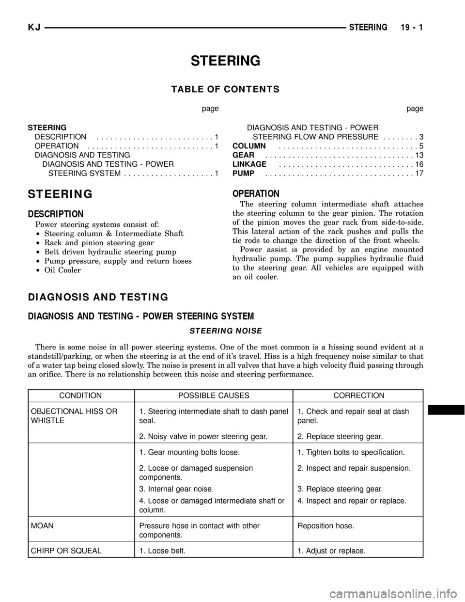
There is some noise in all power steering systems. One of the most common is a hissing sound evident at a
standstill/parking, or when the steering is at the end of it's travel. Hiss is a high frequency noise similar to that
of a water tap being closed slowly. The noise is present in all valves that have a high velocity fluid passing through
an orifice. There is no relationship between this noise and steering performance.
CONDITION POSSIBLE CAUSES CORRECTION
OBJECTIONAL HISS OR
WHISTLE1. Steering intermediate shaft to dash panel
seal.1. Check and repair seal at dash
panel.
2. Noisy valve in power steering gear. 2. Replace steering gear.
1. Gear mounting bolts loose. 1. Tighten bolts to specification.
2. Loose or damaged suspension
components.2. Inspect and repair suspension.
3. Internal gear noise. 3. Replace steering gear.
4. Loose or damaged intermediate shaft or
column.4. Inspect and repair or replace.
MOAN Pressure hose in contact with other
components.Reposition hose.
CHIRP OR SQUEAL 1. Loose belt. 1. Adjust or replace.
KJSTEERING 19 - 1
Page 1432 of 1803
CONDITION POSSIBLE CAUSES CORRECTION
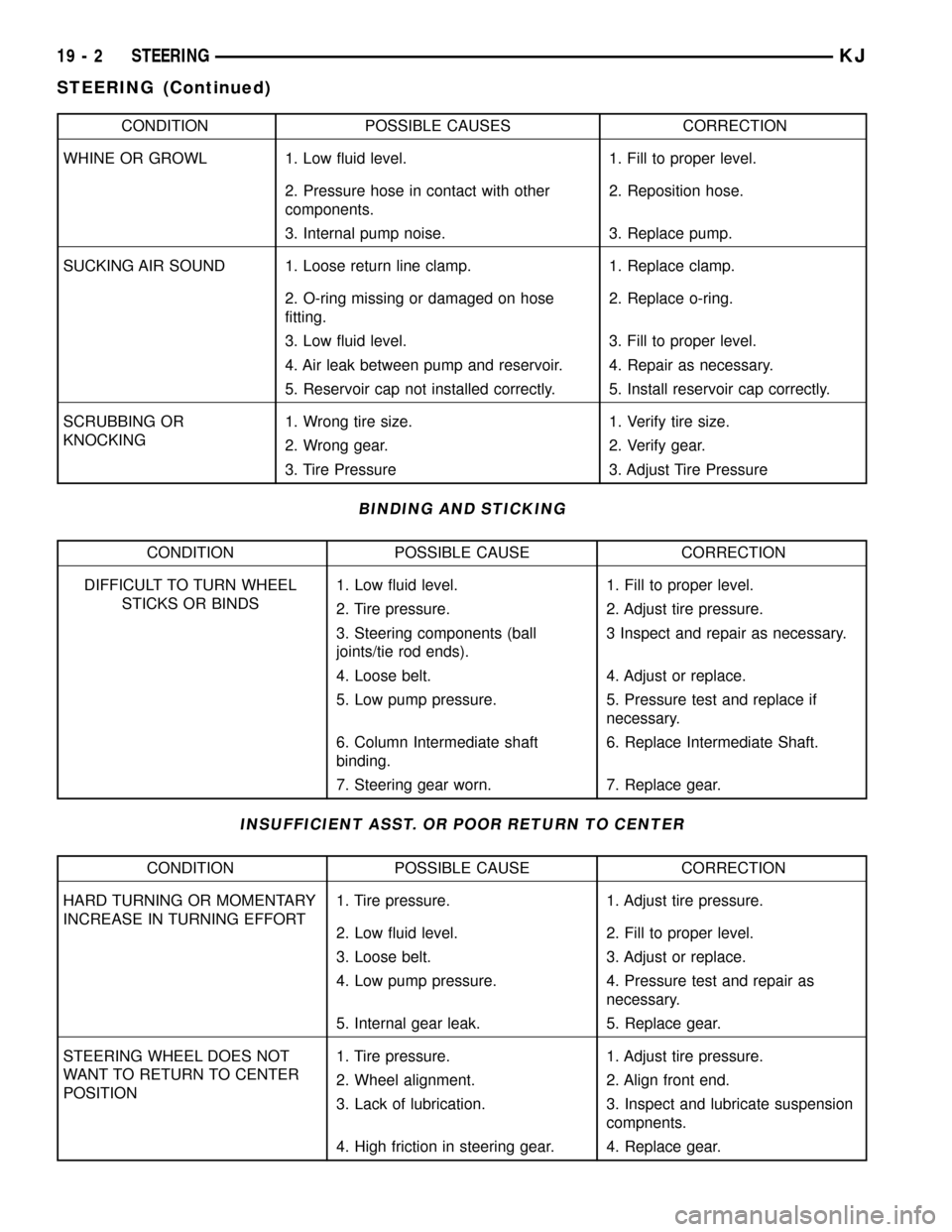
WHINE OR GROWL 1. Low fluid level. 1. Fill to proper level.
2. Pressure hose in contact with other
components.2. Reposition hose.
3. Internal pump noise. 3. Replace pump.
SUCKING AIR SOUND 1. Loose return line clamp. 1. Replace clamp.
2. O-ring missing or damaged on hose
fitting.2. Replace o-ring.
3. Low fluid level. 3. Fill to proper level.
4. Air leak between pump and reservoir. 4. Repair as necessary.
5. Reservoir cap not installed correctly. 5. Install reservoir cap correctly.
SCRUBBING OR
KNOCKING1. Wrong tire size. 1. Verify tire size.
2. Wrong gear. 2. Verify gear.
3. Tire Pressure 3. Adjust Tire Pressure
BINDING AND STICKING
CONDITION POSSIBLE CAUSE CORRECTION
DIFFICULT TO TURN WHEEL
STICKS OR BINDS1. Low fluid level. 1. Fill to proper level.
2. Tire pressure. 2. Adjust tire pressure.
3. Steering components (ball
joints/tie rod ends).3 Inspect and repair as necessary.
4. Loose belt. 4. Adjust or replace.
5. Low pump pressure. 5. Pressure test and replace if
necessary.
6. Column Intermediate shaft
binding.6. Replace Intermediate Shaft.
7. Steering gear worn. 7. Replace gear.
INSUFFICIENT ASST. OR POOR RETURN TO CENTER
CONDITION POSSIBLE CAUSE CORRECTION
HARD TURNING OR MOMENTARY
INCREASE IN TURNING EFFORT1. Tire pressure. 1. Adjust tire pressure.
2. Low fluid level. 2. Fill to proper level.
3. Loose belt. 3. Adjust or replace.
4. Low pump pressure. 4. Pressure test and repair as
necessary.
5. Internal gear leak. 5. Replace gear.
STEERING WHEEL DOES NOT
WANT TO RETURN TO CENTER
POSITION1. Tire pressure. 1. Adjust tire pressure.
2. Wheel alignment. 2. Align front end.
3. Lack of lubrication. 3. Inspect and lubricate suspension
compnents.
4. High friction in steering gear. 4. Replace gear.
19 - 2 STEERINGKJ
STEERING (Continued)
Page 1434 of 1803
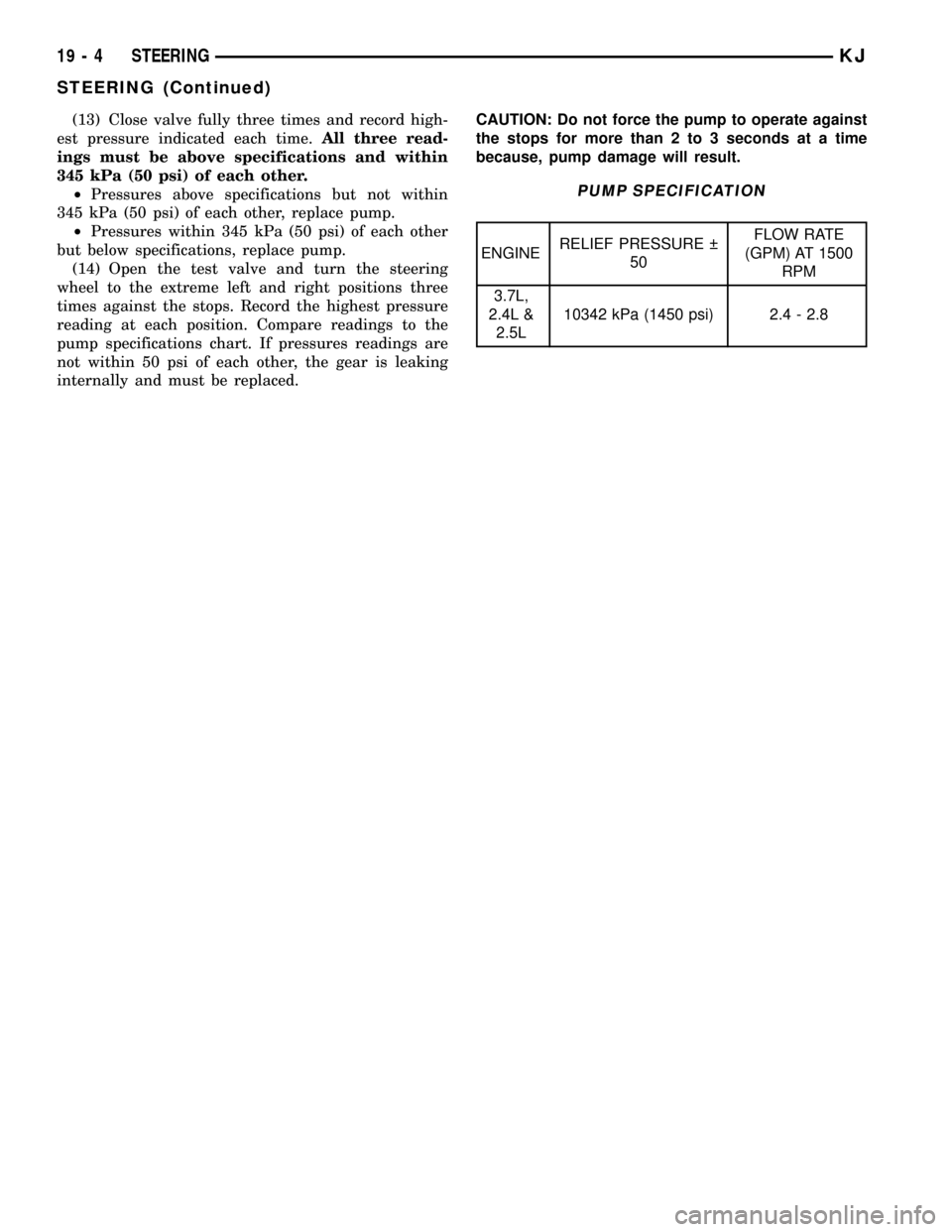
(13) Close valve fully three times and record high-
est pressure indicated each time.All three read-
ings must be above specifications and within
345 kPa (50 psi) of each other.
²Pressures above specifications but not within
345 kPa (50 psi) of each other, replace pump.
²Pressures within 345 kPa (50 psi) of each other
but below specifications, replace pump.
(14) Open the test valve and turn the steering
wheel to the extreme left and right positions three
times against the stops. Record the highest pressure
reading at each position. Compare readings to the
pump specifications chart. If pressures readings are
not within 50 psi of each other, the gear is leaking
internally and must be replaced.CAUTION: Do not force the pump to operate against
the stops for more than 2 to 3 seconds at a time
because, pump damage will result.
PUMP SPECIFICATION
ENGINERELIEF PRESSURE
50FLOW RATE
(GPM) AT 1500
RPM
3.7L,
2.4L &
2.5L10342 kPa (1450 psi) 2.4 - 2.8
19 - 4 STEERINGKJ
STEERING (Continued)
Page 1436 of 1803
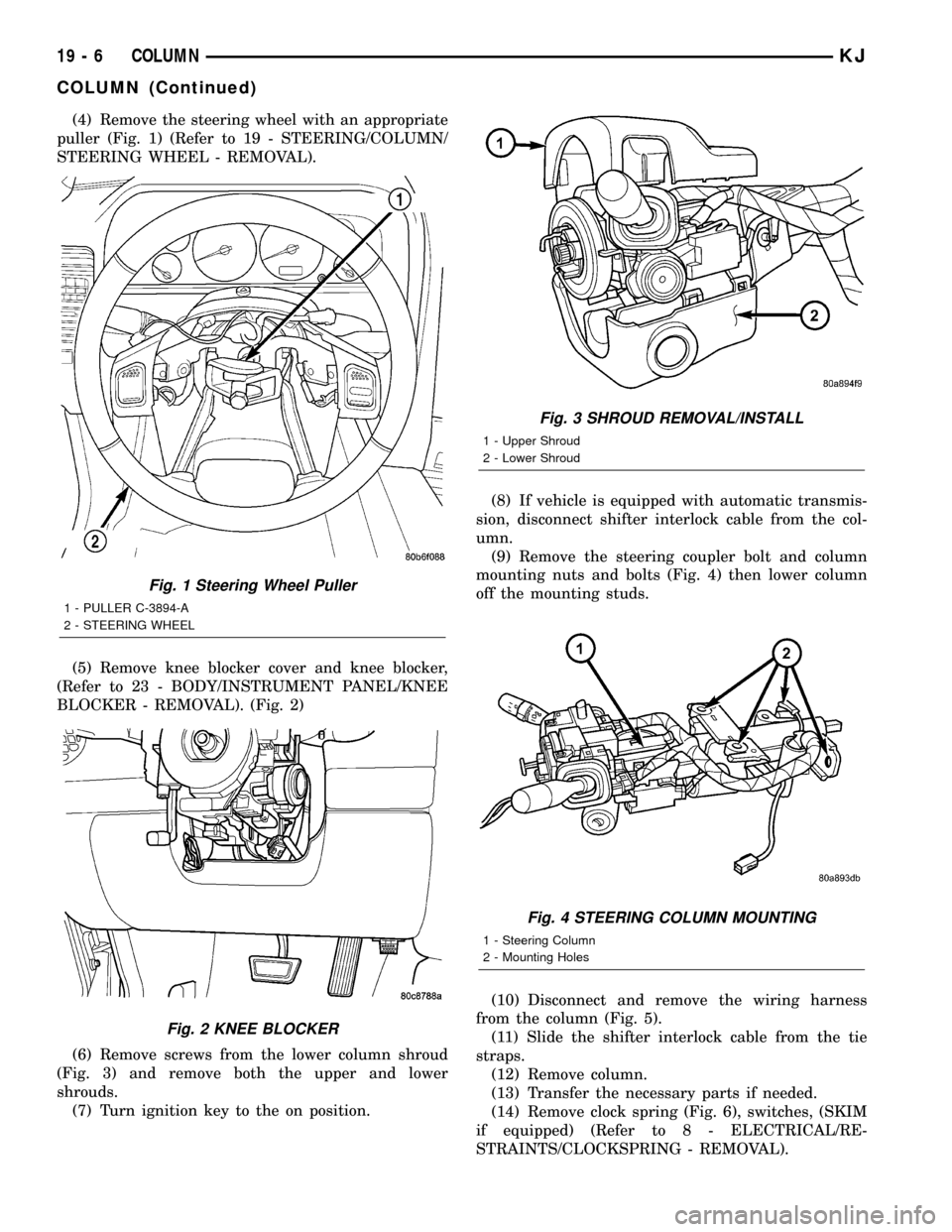
(4) Remove the steering wheel with an appropriate
puller (Fig. 1) (Refer to 19 - STEERING/COLUMN/
STEERING WHEEL - REMOVAL).
(5) Remove knee blocker cover and knee blocker,
(Refer to 23 - BODY/INSTRUMENT PANEL/KNEE
BLOCKER - REMOVAL). (Fig. 2)
(6) Remove screws from the lower column shroud
(Fig. 3) and remove both the upper and lower
shrouds.
(7) Turn ignition key to the on position.(8) If vehicle is equipped with automatic transmis-
sion, disconnect shifter interlock cable from the col-
umn.
(9) Remove the steering coupler bolt and column
mounting nuts and bolts (Fig. 4) then lower column
off the mounting studs.
(10) Disconnect and remove the wiring harness
from the column (Fig. 5).
(11) Slide the shifter interlock cable from the tie
straps.
(12) Remove column.
(13) Transfer the necessary parts if needed.
(14) Remove clock spring (Fig. 6), switches, (SKIM
if equipped) (Refer to 8 - ELECTRICAL/RE-
STRAINTS/CLOCKSPRING - REMOVAL).
Fig. 1 Steering Wheel Puller
1 - PULLER C-3894-A
2 - STEERING WHEEL
Fig. 2 KNEE BLOCKER
Fig. 3 SHROUD REMOVAL/INSTALL
1 - Upper Shroud
2 - Lower Shroud
Fig. 4 STEERING COLUMN MOUNTING
1 - Steering Column
2 - Mounting Holes
19 - 6 COLUMNKJ
COLUMN (Continued)
Page 1445 of 1803
(5) Install the power steering pressure hose
bracket (Fig. 3).
(6) Install the lower coupler bolt and slide the cou-
pler on to the gear (Fig. 2).
(7) Install the tie rod end to the knuckle and
tighten the nuts.
(8) Install the tire and wheel assembly. (Refer to
22 - TIRES/WHEELS/WHEELS - STANDARD PRO-
CEDURE).
(9) Install the skid plate(Refer to 13 - FRAME &
BUMPERS/FRAME/FRONT SKID PLATE - INSTAL-
LATION).(10) Lower the vehicle.
(11) Unlock the steering wheel.
(12) Fill the power steering fluid (Refer to 19 -
STEERING/PUMP - STANDARD PROCEDURE).
(13) Reset the toe and center the steering wheel
(Refer to 2 - SUSPENSION/WHEEL ALIGNMENT -
STANDARD PROCEDURE).
SPECIFICATIONS
TORQUE CHART
TORQUE SPECIFICATIONS
DESCRIPTION N´m Ft. Lbs. In. Lbs.
Rack and Pinion Steering
Gear
Gear to Frame Bolts162 120 Ð
Rack and Pinion Steering
Gear
Intermediate Shaft Bolt49 36 Ð
Tie Rod End
Knuckle Nut108 80 Ð
Tie Rod End
Jam Nut75 55 Ð
Power Steering Line
Pressure Line35 25 Ð
Power Steering Line
Return Line35 25 Ð
SPECIAL TOOLS
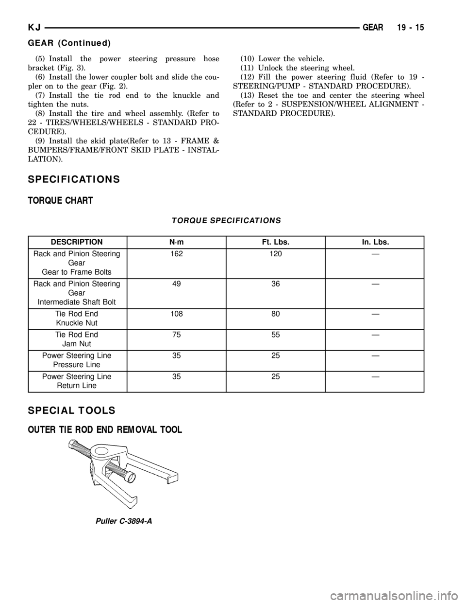
OUTER TIE ROD END REMOVAL TOOL
Puller C-3894-A
KJGEAR 19 - 15
GEAR (Continued)
Page 1446 of 1803

LINKAGE
TABLE OF CONTENTS
page page
LINKAGE
STANDARD PROCEDURE - STEERING
LINKAGE............................16TIE ROD END
REMOVAL.............................16
INSTALLATION.........................16
LINKAGE
STANDARD PROCEDURE - STEERING LINKAGE
The tie rod end and ball stud seals should be
inspected during all oil changes. If a seal is damaged,
replace the tie rod.
CAUTION: If any steering components are replaced
or serviced an alignment must be performed, to
ensure the vehicle meets all alignment specifica-
tions.
TIE ROD END
REMOVAL
(1) Raise and support the vehicle.
(2) Remove the tire and wheel assembly.
NOTE: Mark the tie rod end jam nuts on the steer-
ing gear for easier installation.
(3) Loosen the tie rod end jam nut (Fig. 1).
(4) Remove the tie rod end nut (Fig. 1).
(5) Seperate the tie rod end from the knuckle
using tool C3894A.
NOTE: Count the number of turns when removing.
(6) Remove the tie rod end from the rack (Fig. 1).
INSTALLATION
(1) Install the tie rod end to the rack to the exact
number of turns that it was removed (Fig. 1).(2) Install the tie rod end to the knuckle. Tighten
the nut to 108 N´m (80 ft.lbs).
(3) Tighten the jam nut to 76 N´m (55 ft.lbs). (Fig.
1).
(4) Install the tire and wheel assembly. (Refer to
22 - TIRES/WHEELS/WHEELS - STANDARD PRO-
CEDURE).
(5) Reset the toe and center the steering wheel
(Refer to 2 - SUSPENSION/WHEEL ALIGNMENT -
STANDARD PROCEDURE).
Fig. 1 TIE ROD END
1 - JAM NUT
2 - TIE ROD - INNER
3 - TIE ROD END - OUTER
19 - 16 LINKAGEKJ
Page 1447 of 1803

PUMP
TABLE OF CONTENTS
page page
PUMP
DESCRIPTION.........................17
OPERATION...........................17
STANDARD PROCEDURE - POWER
STEERING PUMP - INITIAL OPERATION....18
REMOVAL
REMOVAL - 3.7L......................18
REMOVAL - 2.4L......................18
INSTALLATION
INSTALLATION - 3.7L..................19
INSTALLATION - 2.4L..................19
SPECIFICATIONS
TORQUE CHART......................19
SPECIAL TOOLS
POWER STEERING PUMP..............20
FLUID COOLER
DESCRIPTION.........................20
OPERATION...........................20
REMOVAL.............................20
INSTALLATION.........................20
HOSES
REMOVAL
REMOVAL - PRESSURE HOSE...........21
REMOVAL - RETURN HOSE (GEAR TO THE
COOLER)...........................21REMOVAL - RETURN HOSE (RESERVOIR
TO THE COOLER).....................21
INSTALLATION
INSTALLATION - PRESSURE HOSE.......21
INSTALLATION - RETURN HOSE (GEAR TO
THE COOLER)........................22
INSTALLATION - RETURN HOSE
(RESERVOIR TO THE COOLER)..........22
POWER STEERING PRESSURE SWITCH
DESCRIPTION.........................22
OPERATION...........................22
REMOVAL.............................22
INSTALLATION.........................22
PULLEY
REMOVAL.............................23
INSTALLATION.........................23
RESERVOIR
REMOVAL
REMOVAL - 3.7L......................24
REMOVAL - 2.4L......................24
INSTALLATION
INSTALLATION - 3.7L..................24
INSTALLATION - 2.4L..................24
PUMP
DESCRIPTION
Hydraulic pressure for the power steering system
is provided by a belt driven power steering pump
(Fig. 1). The pump shaft has a pressed-on high
strength plastic drive pulley that is belt driven by
the crankshaft pulley. The integral reservoir used on
the 3.7L only is attached to the pump body with
spring clips (Fig. 1). The 2.4L uses a remote fluid res-
ervoir (Fig. 2). The power steering pump is connected
to the steering gear by the pressure and return
hoses.
OPERATION
The power steering pump is a constant flow rate
and displacement, vane-type pump. The pump inter-
nal parts operate submerged in fluid. The flow con-
trol orifice is part of the high pressure line fitting.
The pressure relief valve inside the flow control valve
limits the pump pressure.Fig. 1 POWER STEERING PUMP ASSEMBLY
1 - RESERVOIR
2 - CAP
3 - PULLEY
4 - PUMP BODY
5 - RESERVOIR RETAINING CLIPS
KJPUMP 19 - 17