2002 JEEP LIBERTY bedplate torque
[x] Cancel search: bedplate torquePage 1258 of 1803
REMOVAL
NOTE: To remove the crankshaft from the engine,
the engine must be removed from the vehicle.
(1) Remove the engine. Refer to Engine Assembly
in this section for procedure.
(2) Remove the engine oil pump. Refer to Oil
Pump in this section for procedure.
CAUTION: DO NOT pry on the oil pan gasket when
removing the oil pan, The oil pan gasket is mounted
to the cylinder block in three locations and will
remain attached to block when removing oil pan.
Gasket can not be removed with oil pan.
(3) Remove oil pan bolts and oil pan.
(4) Remove the oil pump pickup tube and oil pan
gasket /windage tray.
(5) Remove the bedplate mounting bolts. Note the
location of the two stud bolts for installation.
(6) Remove the connecting rods from the crank-
shaft.
CAUTION: The bedplate to cylinder block mating
surface is a critical sealing surface. Do not pry on
or damage this surface in anyway.
NOTE: The bedplate contains the lower main bear-
ing halves. Use care when handling bedplate as not
to drop or damage bearing halves. Installing main
bearing halves in the wrong position will cause
sever damage to the crankshaft.
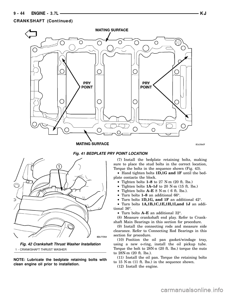
NOTE: The bedplate has pry points cast into it. Use
these points only. The pry points are shown below.
(7) Carefully pry on the pry points (Fig. 41) to
loosen the bedplate then remove the bedplate.
CAUTION: When removing the crankshaft, use care
not to damage bearing surfaces on the crankshaft.
(8) Remove the crankshaft.
(9) Remove the crankshaft tone wheel.
INSPECTION
NOTE: Thoroughly inspect the connecting rod bear-
ing bores and main bearing bores for scoring, blue-
ing or severe scratches. Further disassembly may
be required.
If connecting rod bearing bores show damage, the
cylinder heads must be removed to service the piston
and rod assemblies. If the bedplate or the cylinderblock main bearing bores show damage the engine
must be replaced.
(1) If required, remove the main bearing halves
from the cylinder block and bedplate.
(2) Thoroughly clean the bedplate to cylinder block
sealing surfaces and main bearing bores. Remove all
oil and sealant residue.
(3) Inspect the bedplate main bearing bores for
cracks, scoring or severe blueing. If either condition
exists the engine must be replaced.
(4) Inspect the crankshaft thrust washer for scor-
ing, scratches or blueing. If either condition exist
replace the thrust washer.
(5) Inspect the oil pan gasket/windage tray for
splits, tears or cracks in the gasket sealing surfaces.
Replace gasket as necessary.
INSTALLATION
CAUTION: Main bearings are select fit. Refer to
Crankshaft Main Bearings in this section for proper
bearing selections.
CAUTION: When installing crankshaft, use care not
to damage bearing surfaces on the crankshaft.
NOTE: Apply sealant to the tone wheel retaining
screws prior to installation.
(1) Lubricate upper main bearing halves with
clean engine oil.
(2) Install the crankshaft tone wheel. Torque the
mounting screws to 22 N´m (21 ft. lbs.).
(3) Position crankshaft in cylinder block.
(4) Install the thrust washers (Fig. 42).
CAUTION: The bedplate to cylinder block mating
surface must be coated with MoparTEngine RTV
sealant prior to installation. Failure to do so will
cause severe oil leaks.
NOTE: Make sure that the bedplate and cylinder
block sealing surfaces are clean and free of oil or
other contaminants. Contaminants on the sealing
surfaces may cause main bearing distortion and/or
oil leaks.
(5) Apply a 2.5mm (0.100 inch) bead of Mopart
Engine RTV sealant to the cylinder block-to-bedplate
mating surface as shown.
(6) Coat the crankshaft main bearing journals
with clean engine oil and position the bedplate onto
the cylinder block.
KJENGINE - 3.7L 9 - 43
CRANKSHAFT (Continued)
Page 1259 of 1803
NOTE: Lubricate the bedplate retaining bolts with
clean engine oil prior to installation.(7) Install the bedplate retaining bolts, making
sure to place the stud bolts in the correct location,
Torque the bolts in the sequence shown (Fig. 43).
²Hand tighten bolts1D,1G and 1Funtil the bed-
plate contacts the block.
²Tighten bolts1±8to 27 N´m (20 ft. lbs.)
²Tighten bolts1A±1Jto 20 N´m (15 ft. lbs.)
²Tighten boltsA±E8 N´m ( 6 ft. lbs.).
²Turn bolts1±8an additional 66É.
²Turn bolts1D,1G, and 1Fan additional 42É.
²Turn bolts1A,1B,1C,1E,1H,1I,and 1Jan addi-
tional 36É.
²Turn boltsA±Ean additional 32É.
(8) Measure crankshaft end play. Refer to Crank-
shaft Main Bearings in this section for procedure.
(9) Install the connecting rods and measure side
clearance. Refer to Connecting Rod Bearings in this
section for procedure.
(10) Position the oil pan gasket/windage tray,
using a new o-ring, install the oil pickup tube.
Torque the bolt to 28N´n (20 ft. lbs.) torque the nuts
to 28N´m (20 ft. lbs.).
(11) Install the oil pan. Torque the retaining bolts
to 15 N´m (11 ft. lbs.) in the sequence shown.
(12) Install the engine.
Fig. 41 BEDPLATE PRY POINT LOCATION
Fig. 42 Crankshaft Thrust Washer Installation
1 - CRANKSHAFT THRUST WASHER
9 - 44 ENGINE - 3.7LKJ
CRANKSHAFT (Continued)
Page 1301 of 1803
(7) Crank engine until maximum pressure is
reached on gage. Record this pressure as #1 cylinder
pressure.
(8) Repeat the previous step for all remaining cyl-
inders.
(9) Compression should not be less than 689 kPa
(100 psi) and not vary more than 25 percent from cyl-
inder to cylinder.
(10) If one or more cylinders have abnormally low
compression pressures, repeat the compression test.
(11) If the same cylinder or cylinders repeat an
abnormally low reading on the second compression
test, it could indicate the existence of a problem in
the cylinder in question.The recommended com-
pression pressures are to be used only as a
guide to diagnosing engine problems. An engine
should not be disassembled to determine the
cause of low compression unless some malfunc-
tion is present.
DIAGNOSIS AND TESTING - ENGINE OIL LEAK
INSPECTION
Begin with a thorough visual inspection of the
engine, particularly at the area of the suspected leak.
If an oil leak source is not readily identifiable, the
following steps should be followed:
(1) Do not clean or degrease the engine at this
time because some solvents may cause rubber to
swell, temporarily stopping the leak.
(2) Add an oil soluble dye (use as recommended by
manufacturer). Start the engine and let idle for
approximately 15 minutes. Check the oil dipstick to
make sure the dye is thoroughly mixed as indicated
with a bright yellow color under a black light.
(3) Using a black light, inspect the entire engine
for fluorescent dye, particularly at the suspected area
of oil leak. If the oil leak is found and identified,
repair as necessary.
(4) If dye is not observed, drive the vehicle at var-
ious speeds for approximately 24 km (15 miles), and
repeat inspection.
(5)If the oil leak source is not positively
identified at this time, proceed with the air leak
detection test method as follows:
²Disconnect the fresh air hose (make-up air) at
the cylinder head cover and plug or cap the nipple on
the cover.
²Remove the PCV valve hose from the cylinder
head cover. Cap or plug the PCV valve nipple on the
cover.
²Attach an air hose with pressure gauge and reg-
ulator to the dipstick tube.
CAUTION: Do not subject the engine assembly to
more than 20.6 kpa (3 PSI) of test pressure.²Gradually apply air pressure from 1 psi to 2.5
psi maximum while applying soapy water at the sus-
pected source. Adjust the regulator to the suitable
test pressure that provides the best bubbles which
will pinpoint the leak source. If the oil leak is
detected and identified, repair per service manual
procedures.
²If the leakage occurs at the crankshaft rear oil
seal area, refer to the section, Inspection for Rear
Seal Area Leak.
(6) If no leaks are detected, turn off the air supply.
Remove the air hose, all plugs, and caps. Install the
PCV valve and fresh air hose (make-up air). Proceed
to next step.
(7) Clean the oil off the suspect oil leak area using
a suitable solvent. Drive the vehicle at various
speeds approximately 24 km (15 miles). Inspect the
engine for signs of an oil leak by using a black light.
NOTE: If oil leakage is observed at the dipstick tube
to block location; remove the tube, clean and reseal
using MoparTStud & Bearing Mount (press fit tube
applications only), and for O-ring style tubes,
remove tube and replace the O-ring seal.
INSPECTION FOR REAR SEAL AREA LEAKS
Since it is sometimes difficult to determine the
source of an oil leak in the rear seal area of the
engine, a more involved inspection is necessary. The
following steps should be followed to help pinpoint
the source of the leak.
If the leakage occurs at the crankshaft rear oil seal
area:
(1) Disconnect the battery.
(2) Raise the vehicle.
(3) Remove torque converter or clutch housing
cover and inspect rear of block for evidence of oil.
Use a black light to check for the oil leak. If a leak is
present in this area, remove transmission for further
inspection.
(a) Circular spray pattern generally indicates
seal leakage or crankshaft damage.
(b) Where leakage tends to run straight down,
possible causes are a porous block, oil gallery cup
plug, bedplate to cylinder block mating surfaces
and seal bore. See proper repair procedures for
these items.
(4) If no leaks are detected, pressurize the crank-
case as previously described.
CAUTION: Do not exceed 20.6 kPa (3 psi).
(5) If the leak is not detected, very slowly turn the
crankshaft and watch for leakage. If a leak is
detected between the crankshaft and seal while
slowly turning the crankshaft, it is possible the
9s - 4 ENGINEKJ
ENGINE - 2.4L (Continued)
Page 1313 of 1803
DESCRIPTION SPECIFICATION
Valve Springs
Free Length (Approx.) 48.4 mm
(1.905 in.)
Nominal Force (Valve
Closed)338 N @ 38.0 mm
(75.98 lbs. @ 1.496 in.)
Nominal Force (Valve
Open)607 N @ 29.75 mm
(136 lbs. @ 1.172 in.)
Installed Height 38.00 mm
(1.496 in.)
Number of Coils 7.82
Wire Diameter 3.86 mm
(1.496 in.)
Oil Pump
Clearance Over Rotors
(Max.)0.10 mm
(0.004 in.)
Cover Out-of-Flat (Max.) 0.025 mm
(0.001 in.)
Inner Rotor Thickness
(Min.)9.40 mm
(0.370 in.)
Outer Rotor Thickness
(Min.)9.40 mm
(0.370 in.)
Outer Rotor Clearance
(Max.)0.039 mm
(0.015 in.)
Outer Rotor Diameter
(Min.)79.95 mm
(3.148 in.)
Tip Clearance Between
Rotors (Max.)0.20 mm
(0.008 in.)
Oil Pressure
At Curb Idle Speed* 25 kPa
(4 psi)
At 3000 rpm 170±550 kPa
(25±80 psi)
CAUTION:
*If pressure is ZERO at curb idle, DO NOT run engine
at 3000 rpm.SPECIFICATIONS - TORQUE
DESCRIPTION N´mFt.
Lbs.In.
Lbs.
Balance Shaft Carrier to
BlockÐBolts54 40 Ð
Balance Shaft Gear
CoverÐDouble Ended
Fastener12 Ð 105
Balance Shaft SprocketÐ
Bolt28 Ð 250
Balance Shaft Chain
TensionerÐBolts12 Ð 105
Balance Shaft Carrier
CoverÐBolts12 Ð 105
Camshaft SprocketÐBolt 101 75 Ð
Connecting Rod
CapÐBolts54 +
1¤4
turn40
+1¤4
turnÐ
Crankshaft Main Bearing
Cap/Bedplate
ÐM8 Bolts 34 250
ÐM11 Bolts 41 +
1¤4
Turn30
+1¤4
TurnÐ
Crankshaft Damper 136 100 Ð
Cylinder HeadÐBolts (Refer to 9 - ENGINE/
CYLINDER HEAD -
INSTALLATION)
Cylinder Head CoverÐ
Bolts12 Ð 105
Flex Plate to Crankshaft 95 70 Ð
Flywheel Mounting Bolts 81 60 Ð
Engine Mount Bracket
RightÐBolts61 45 Ð
Engine MountingÐBolts (Refer to 9 ENGINE/
ENGINE MOUNTING)
Exhaust Manifold to
Cylinder HeadÐBolts23 Ð 200
Exhaust Manifold Heat
ShieldÐBolts12 Ð 105
Intake Manifold - Lower
ÐBolts28 Ð 250
Oil Filter 20 15 Ð
Oil PanÐBolts 12 Ð 105
Oil Pan DrainÐPlug 27 20 Ð
Oil Pump to BlockÐBolts 28 Ð 250
9s - 16 ENGINEKJ
ENGINE - 2.4L (Continued)
Page 1331 of 1803
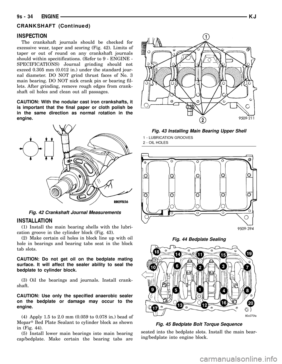
INSPECTION
The crankshaft journals should be checked for
excessive wear, taper and scoring (Fig. 42). Limits of
taper or out of round on any crankshaft journals
should within specitifications. (Refer to 9 - ENGINE -
SPECIFICATIONS) Journal grinding should not
exceed 0.305 mm (0.012 in.) under the standard jour-
nal diameter. DO NOT grind thrust faces of No. 3
main bearing. DO NOT nick crank pin or bearing fil-
lets. After grinding, remove rough edges from crank-
shaft oil holes and clean out all passages.
CAUTION: With the nodular cast iron crankshafts, it
is important that the final paper or cloth polish be
in the same direction as normal rotation in the
engine.
INSTALLATION
(1) Install the main bearing shells with the lubri-
cation groove in the cylinder block (Fig. 43).
(2) Make certain oil holes in block line up with oil
hole in bearings and bearing tabs seat in the block
tab slots.
CAUTION: Do not get oil on the bedplate mating
surface. It will affect the sealer ability to seal the
bedplate to cylinder block.
(3) Oil the bearings and journals. Install crank-
shaft.
CAUTION: Use only the specified anaerobic sealer
on the bedplate or damage may occur to the
engine.
(4) Apply 1.5 to 2.0 mm (0.059 to 0.078 in.) bead of
MopartBed Plate Sealant to cylinder block as shown
in (Fig. 44).
(5) Install lower main bearings into main bearing
cap/bedplate. Make certain the bearing tabs areseated into the bedplate slots. Install the main bear-
ing/bedplate into engine block.
Fig. 42 Crankshaft Journal Measurements
Fig. 43 Installing Main Bearing Upper Shell
1 - LUBRICATION GROOVES
2 - OIL HOLES
Fig. 44 Bedplate Sealing
Fig. 45 Bedplate Bolt Torque Sequence
9s - 34 ENGINEKJ
CRANKSHAFT (Continued)
Page 1332 of 1803
(6) Before installing the bolts the threads should
be oiled with clean engine oil, wipe off any excess oil.
(7) Install main bearing bedplate to engine block
bolts 11, 17, and 20 finger tight. Tighten these bolts
down together until the bedplate contacts the cylin-
der block.
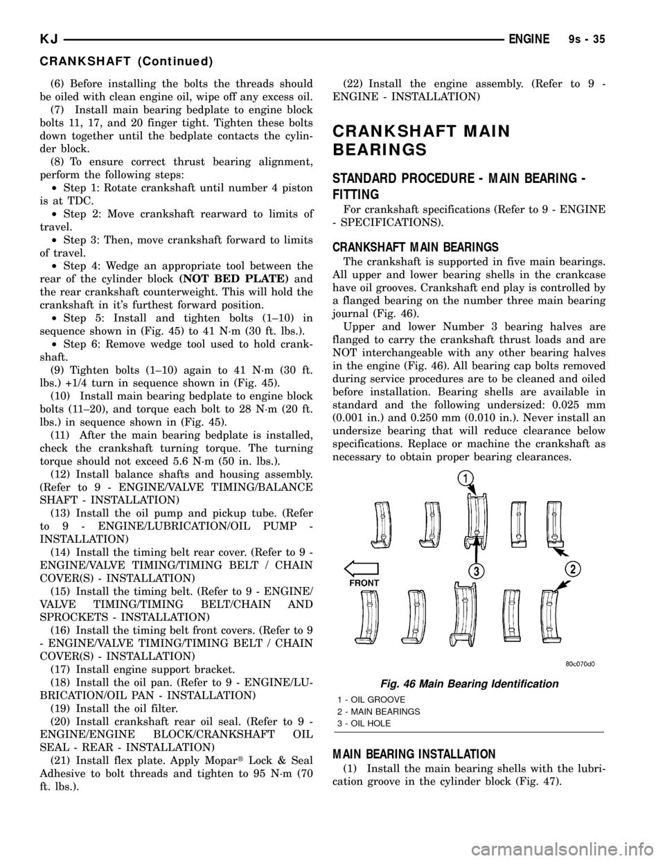
(8) To ensure correct thrust bearing alignment,
perform the following steps:
²Step 1: Rotate crankshaft until number 4 piston
is at TDC.
²Step 2: Move crankshaft rearward to limits of
travel.
²Step 3: Then, move crankshaft forward to limits
of travel.
²Step 4: Wedge an appropriate tool between the
rear of the cylinder block(NOT BED PLATE)and
the rear crankshaft counterweight. This will hold the
crankshaft in it's furthest forward position.
²Step 5: Install and tighten bolts (1±10) in
sequence shown in (Fig. 45) to 41 N´m (30 ft. lbs.).
²Step 6: Remove wedge tool used to hold crank-
shaft.
(9) Tighten bolts (1±10) again to 41 N´m (30 ft.
lbs.) +1/4 turn in sequence shown in (Fig. 45).
(10) Install main bearing bedplate to engine block
bolts (11±20), and torque each bolt to 28 N´m (20 ft.
lbs.) in sequence shown in (Fig. 45).
(11) After the main bearing bedplate is installed,
check the crankshaft turning torque. The turning
torque should not exceed 5.6 N´m (50 in. lbs.).
(12) Install balance shafts and housing assembly.
(Refer to 9 - ENGINE/VALVE TIMING/BALANCE
SHAFT - INSTALLATION)
(13) Install the oil pump and pickup tube. (Refer
to 9 - ENGINE/LUBRICATION/OIL PUMP -
INSTALLATION)
(14) Install the timing belt rear cover. (Refer to 9 -
ENGINE/VALVE TIMING/TIMING BELT / CHAIN
COVER(S) - INSTALLATION)
(15) Install the timing belt. (Refer to 9 - ENGINE/
VALVE TIMING/TIMING BELT/CHAIN AND
SPROCKETS - INSTALLATION)
(16) Install the timing belt front covers. (Refer to 9
- ENGINE/VALVE TIMING/TIMING BELT / CHAIN
COVER(S) - INSTALLATION)
(17) Install engine support bracket.
(18) Install the oil pan. (Refer to 9 - ENGINE/LU-
BRICATION/OIL PAN - INSTALLATION)
(19) Install the oil filter.
(20) Install crankshaft rear oil seal. (Refer to 9 -
ENGINE/ENGINE BLOCK/CRANKSHAFT OIL
SEAL - REAR - INSTALLATION)
(21) Install flex plate. Apply MopartLock & Seal
Adhesive to bolt threads and tighten to 95 N´m (70
ft. lbs.).(22) Install the engine assembly. (Refer to 9 -
ENGINE - INSTALLATION)
CRANKSHAFT MAIN
BEARINGS
STANDARD PROCEDURE - MAIN BEARING -
FITTING
For crankshaft specifications (Refer to 9 - ENGINE
- SPECIFICATIONS).
CRANKSHAFT MAIN BEARINGS
The crankshaft is supported in five main bearings.
All upper and lower bearing shells in the crankcase
have oil grooves. Crankshaft end play is controlled by
a flanged bearing on the number three main bearing
journal (Fig. 46).
Upper and lower Number 3 bearing halves are
flanged to carry the crankshaft thrust loads and are
NOT interchangeable with any other bearing halves
in the engine (Fig. 46). All bearing cap bolts removed
during service procedures are to be cleaned and oiled
before installation. Bearing shells are available in
standard and the following undersized: 0.025 mm
(0.001 in.) and 0.250 mm (0.010 in.). Never install an
undersize bearing that will reduce clearance below
specifications. Replace or machine the crankshaft as
necessary to obtain proper bearing clearances.
MAIN BEARING INSTALLATION
(1) Install the main bearing shells with the lubri-
cation groove in the cylinder block (Fig. 47).
Fig. 46 Main Bearing Identification
1 - OIL GROOVE
2 - MAIN BEARINGS
3 - OIL HOLE
KJENGINE9s-35
CRANKSHAFT (Continued)
Page 1333 of 1803
(2) Make certain oil holes in block line up with oil
holes in bearings. Bearing tabs must seat in the
block tab slots.
CAUTION: Do not get oil on the bedplate mating
surface. It will may effect the sealer ability to seal
the bedplate to cylinder block.
(3) Oil the bearings and journals and install
crankshaft.
CAUTION: Use only the specified anaerobic sealer
on the bedplate or damage may occur to the
engine. Ensure that both cylinder block and bed-
plate surfaces are clean.
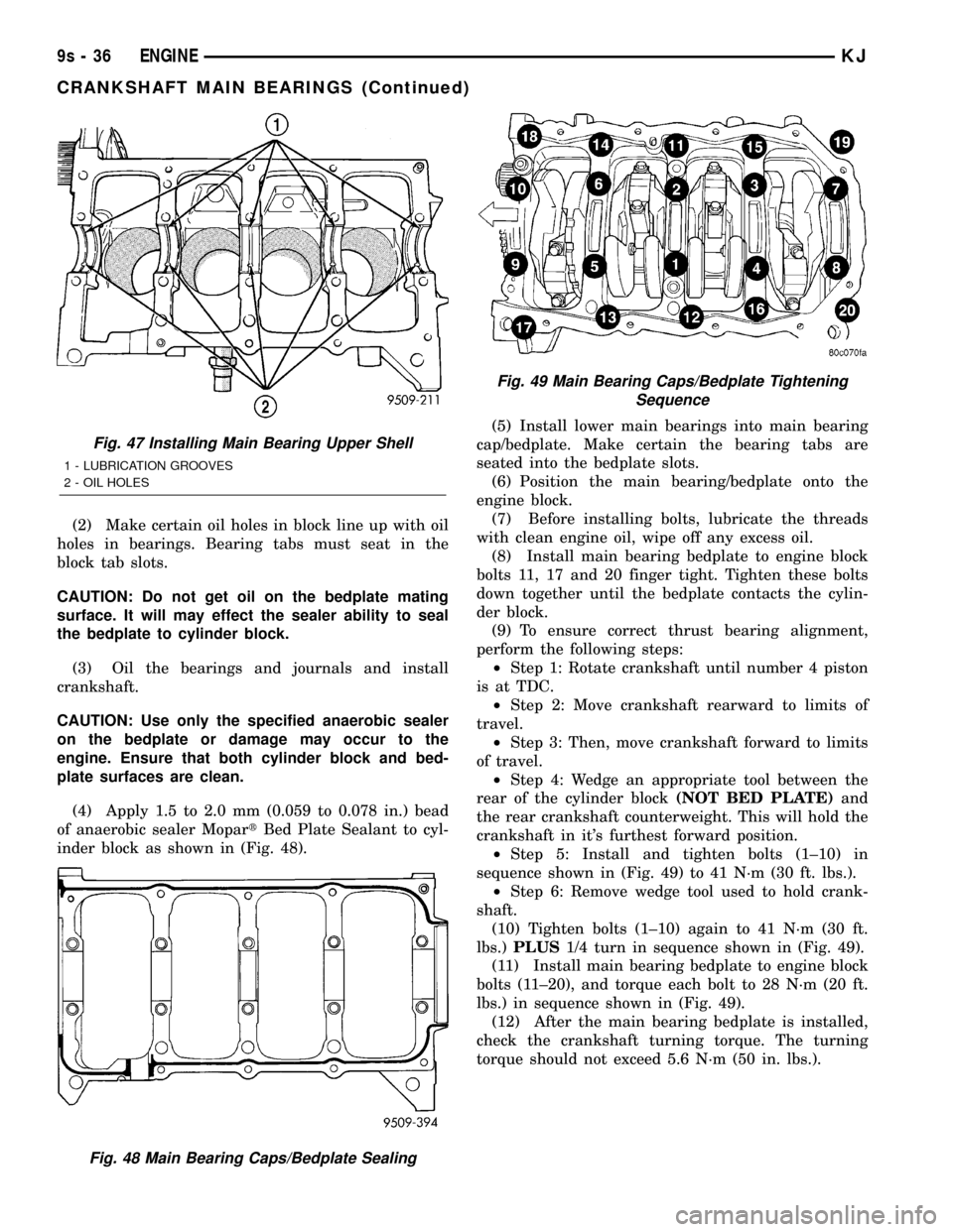
(4) Apply 1.5 to 2.0 mm (0.059 to 0.078 in.) bead
of anaerobic sealer MopartBed Plate Sealant to cyl-
inder block as shown in (Fig. 48).(5) Install lower main bearings into main bearing
cap/bedplate. Make certain the bearing tabs are
seated into the bedplate slots.
(6) Position the main bearing/bedplate onto the
engine block.
(7) Before installing bolts, lubricate the threads
with clean engine oil, wipe off any excess oil.
(8) Install main bearing bedplate to engine block
bolts 11, 17 and 20 finger tight. Tighten these bolts
down together until the bedplate contacts the cylin-
der block.
(9) To ensure correct thrust bearing alignment,
perform the following steps:
²Step 1: Rotate crankshaft until number 4 piston
is at TDC.
²Step 2: Move crankshaft rearward to limits of
travel.
²Step 3: Then, move crankshaft forward to limits
of travel.
²Step 4: Wedge an appropriate tool between the
rear of the cylinder block(NOT BED PLATE)and
the rear crankshaft counterweight. This will hold the
crankshaft in it's furthest forward position.
²Step 5: Install and tighten bolts (1±10) in
sequence shown in (Fig. 49) to 41 N´m (30 ft. lbs.).
²Step 6: Remove wedge tool used to hold crank-
shaft.
(10) Tighten bolts (1±10) again to 41 N´m (30 ft.
lbs.)PLUS1/4 turn in sequence shown in (Fig. 49).
(11) Install main bearing bedplate to engine block
bolts (11±20), and torque each bolt to 28 N´m (20 ft.
lbs.) in sequence shown in (Fig. 49).
(12) After the main bearing bedplate is installed,
check the crankshaft turning torque. The turning
torque should not exceed 5.6 N´m (50 in. lbs.).
Fig. 47 Installing Main Bearing Upper Shell
1 - LUBRICATION GROOVES
2 - OIL HOLES
Fig. 48 Main Bearing Caps/Bedplate Sealing
Fig. 49 Main Bearing Caps/Bedplate Tightening
Sequence
9s - 36 ENGINEKJ
CRANKSHAFT MAIN BEARINGS (Continued)