2002 JEEP LIBERTY tire pressure
[x] Cancel search: tire pressurePage 1308 of 1803
MopartGasket Sealant in an aerosol can should be
applied using a thin, even coat sprayed completely
over both surfaces to be joined, and both sides of a
gasket. Then proceed with assembly. Material in a
can w/applicator can be brushed on evenly over the
sealing surfaces. Material in an aerosol can should be
used on engines with multi-layer steel gaskets.
STANDARD PROCEDURE - ENGINE GASKET
SURFACE PREPARATION
To ensure engine gasket sealing, proper surface
preparation must be performed, especially with the
use of aluminum engine components and multi-layer
steel cylinder head gaskets.
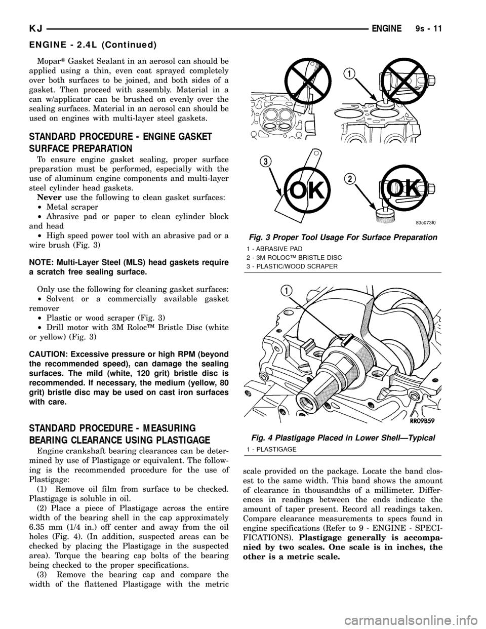
Neveruse the following to clean gasket surfaces:
²Metal scraper
²Abrasive pad or paper to clean cylinder block
and head
²High speed power tool with an abrasive pad or a
wire brush (Fig. 3)
NOTE: Multi-Layer Steel (MLS) head gaskets require
a scratch free sealing surface.
Only use the following for cleaning gasket surfaces:
²Solvent or a commercially available gasket
remover
²Plastic or wood scraper (Fig. 3)
²Drill motor with 3M RolocŸ Bristle Disc (white
or yellow) (Fig. 3)
CAUTION: Excessive pressure or high RPM (beyond
the recommended speed), can damage the sealing
surfaces. The mild (white, 120 grit) bristle disc is
recommended. If necessary, the medium (yellow, 80
grit) bristle disc may be used on cast iron surfaces
with care.
STANDARD PROCEDURE - MEASURING
BEARING CLEARANCE USING PLASTIGAGE
Engine crankshaft bearing clearances can be deter-
mined by use of Plastigage or equivalent. The follow-
ing is the recommended procedure for the use of
Plastigage:
(1) Remove oil film from surface to be checked.
Plastigage is soluble in oil.
(2) Place a piece of Plastigage across the entire
width of the bearing shell in the cap approximately
6.35 mm (1/4 in.) off center and away from the oil
holes (Fig. 4). (In addition, suspected areas can be
checked by placing the Plastigage in the suspected
area). Torque the bearing cap bolts of the bearing
being checked to the proper specifications.
(3) Remove the bearing cap and compare the
width of the flattened Plastigage with the metricscale provided on the package. Locate the band clos-
est to the same width. This band shows the amount
of clearance in thousandths of a millimeter. Differ-
ences in readings between the ends indicate the
amount of taper present. Record all readings taken.
Compare clearance measurements to specs found in
engine specifications (Refer to 9 - ENGINE - SPECI-
FICATIONS).Plastigage generally is accompa-
nied by two scales. One scale is in inches, the
other is a metric scale.
Fig. 3 Proper Tool Usage For Surface Preparation
1 - ABRASIVE PAD
2 - 3M ROLOCŸ BRISTLE DISC
3 - PLASTIC/WOOD SCRAPER
Fig. 4 Plastigage Placed in Lower ShellÐTypical
1 - PLASTIGAGE
KJENGINE9s-11
ENGINE - 2.4L (Continued)
Page 1432 of 1803
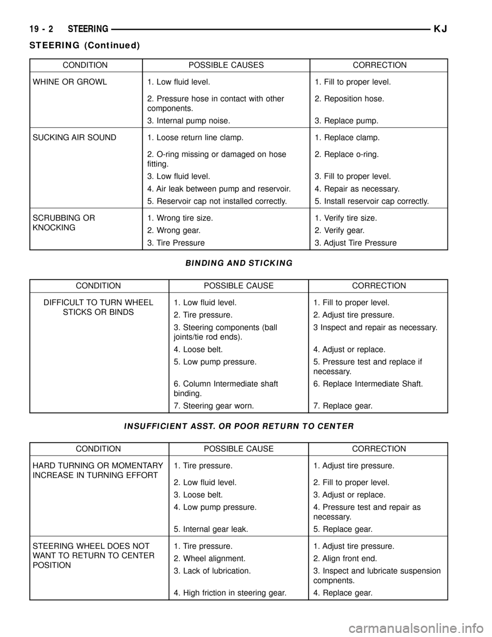
CONDITION POSSIBLE CAUSES CORRECTION
WHINE OR GROWL 1. Low fluid level. 1. Fill to proper level.
2. Pressure hose in contact with other
components.2. Reposition hose.
3. Internal pump noise. 3. Replace pump.
SUCKING AIR SOUND 1. Loose return line clamp. 1. Replace clamp.
2. O-ring missing or damaged on hose
fitting.2. Replace o-ring.
3. Low fluid level. 3. Fill to proper level.
4. Air leak between pump and reservoir. 4. Repair as necessary.
5. Reservoir cap not installed correctly. 5. Install reservoir cap correctly.
SCRUBBING OR
KNOCKING1. Wrong tire size. 1. Verify tire size.
2. Wrong gear. 2. Verify gear.
3. Tire Pressure 3. Adjust Tire Pressure
BINDING AND STICKING
CONDITION POSSIBLE CAUSE CORRECTION
DIFFICULT TO TURN WHEEL
STICKS OR BINDS1. Low fluid level. 1. Fill to proper level.
2. Tire pressure. 2. Adjust tire pressure.
3. Steering components (ball
joints/tie rod ends).3 Inspect and repair as necessary.
4. Loose belt. 4. Adjust or replace.
5. Low pump pressure. 5. Pressure test and replace if
necessary.
6. Column Intermediate shaft
binding.6. Replace Intermediate Shaft.
7. Steering gear worn. 7. Replace gear.
INSUFFICIENT ASST. OR POOR RETURN TO CENTER
CONDITION POSSIBLE CAUSE CORRECTION
HARD TURNING OR MOMENTARY
INCREASE IN TURNING EFFORT1. Tire pressure. 1. Adjust tire pressure.
2. Low fluid level. 2. Fill to proper level.
3. Loose belt. 3. Adjust or replace.
4. Low pump pressure. 4. Pressure test and repair as
necessary.
5. Internal gear leak. 5. Replace gear.
STEERING WHEEL DOES NOT
WANT TO RETURN TO CENTER
POSITION1. Tire pressure. 1. Adjust tire pressure.
2. Wheel alignment. 2. Align front end.
3. Lack of lubrication. 3. Inspect and lubricate suspension
compnents.
4. High friction in steering gear. 4. Replace gear.
19 - 2 STEERINGKJ
STEERING (Continued)
Page 1433 of 1803
LOOSE STEERING AND VEHICLE LEAD
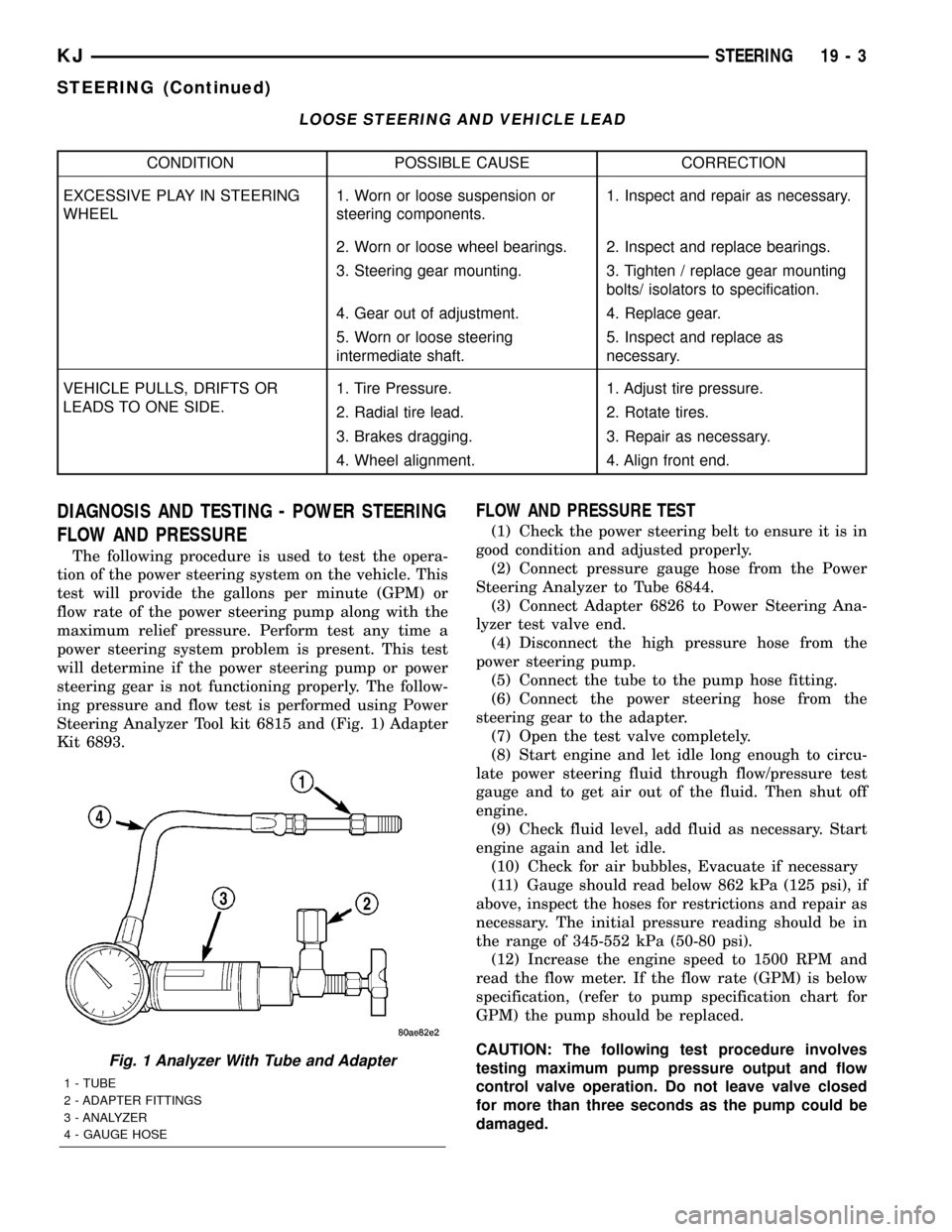
CONDITION POSSIBLE CAUSE CORRECTION
EXCESSIVE PLAY IN STEERING
WHEEL1. Worn or loose suspension or
steering components.1. Inspect and repair as necessary.
2. Worn or loose wheel bearings. 2. Inspect and replace bearings.
3. Steering gear mounting. 3. Tighten / replace gear mounting
bolts/ isolators to specification.
4. Gear out of adjustment. 4. Replace gear.
5. Worn or loose steering
intermediate shaft.5. Inspect and replace as
necessary.
VEHICLE PULLS, DRIFTS OR
LEADS TO ONE SIDE.1. Tire Pressure. 1. Adjust tire pressure.
2. Radial tire lead. 2. Rotate tires.
3. Brakes dragging. 3. Repair as necessary.
4. Wheel alignment. 4. Align front end.
DIAGNOSIS AND TESTING - POWER STEERING
FLOW AND PRESSURE
The following procedure is used to test the opera-
tion of the power steering system on the vehicle. This
test will provide the gallons per minute (GPM) or
flow rate of the power steering pump along with the
maximum relief pressure. Perform test any time a
power steering system problem is present. This test
will determine if the power steering pump or power
steering gear is not functioning properly. The follow-
ing pressure and flow test is performed using Power
Steering Analyzer Tool kit 6815 and (Fig. 1) Adapter
Kit 6893.
FLOW AND PRESSURE TEST
(1) Check the power steering belt to ensure it is in
good condition and adjusted properly.
(2) Connect pressure gauge hose from the Power
Steering Analyzer to Tube 6844.
(3) Connect Adapter 6826 to Power Steering Ana-
lyzer test valve end.
(4) Disconnect the high pressure hose from the
power steering pump.
(5) Connect the tube to the pump hose fitting.
(6) Connect the power steering hose from the
steering gear to the adapter.
(7) Open the test valve completely.
(8) Start engine and let idle long enough to circu-
late power steering fluid through flow/pressure test
gauge and to get air out of the fluid. Then shut off
engine.
(9) Check fluid level, add fluid as necessary. Start
engine again and let idle.
(10) Check for air bubbles, Evacuate if necessary
(11) Gauge should read below 862 kPa (125 psi), if
above, inspect the hoses for restrictions and repair as
necessary. The initial pressure reading should be in
the range of 345-552 kPa (50-80 psi).
(12) Increase the engine speed to 1500 RPM and
read the flow meter. If the flow rate (GPM) is below
specification, (refer to pump specification chart for
GPM) the pump should be replaced.
CAUTION: The following test procedure involves
testing maximum pump pressure output and flow
control valve operation. Do not leave valve closed
for more than three seconds as the pump could be
damaged.
Fig. 1 Analyzer With Tube and Adapter
1 - TUBE
2 - ADAPTER FITTINGS
3 - ANALYZER
4 - GAUGE HOSE
KJSTEERING 19 - 3
STEERING (Continued)
Page 1443 of 1803

GEAR
TABLE OF CONTENTS
page page
GEAR
DESCRIPTION.........................13
OPERATION...........................13
REMOVAL
REMOVAL - 4WD......................13
REMOVAL - 2WD......................14
INSTALLATION
INSTALLATION - 4WD..................14INSTALLATION - 2WD..................14
SPECIFICATIONS
TORQUE CHART......................15
SPECIAL TOOLS
OUTER TIE ROD END REMOVAL TOOL....15
GEAR
DESCRIPTION
A rack and pinion steering gear (Fig. 1) is made up
of two main components, the pinon shaft and the
rack. The gear cannot be adjusted or internally ser-
viced. If a malfunction or a fluid leak occurs, the gear
must be replaced as an assembly.
OPERATION
The steering column intermediate shaft is attached
to the gear pinion. The rotation of the pinion moves
the gear rack from side-to-side. This lateral action of
the rack pushes and pulls the tie rods, which are
connected to the steering knuckles to change the
direction of the front wheels.
REMOVAL
REMOVAL - 4WD
(1) Siphon the power steering fluid from the power
steering reservoir.
(2) Lock the steering wheel to prevent spinning of
the clockspring.
(3) Raise and support the vehicle.
(4) Remove the skid plate from under the front
end to gain access to the gear (Refer to 13 - FRAME
& BUMPERS/FRAME/FRONT SKID PLATE -
REMOVAL).
(5) Remove the front tire and wheel assemblies.
NOTE: Mark the alignment adjusting cams for eas-
ier installation.
(6) Remove the lower control arms. (Refer to 2 -
SUSPENSION/FRONT/LOWER CONTROL ARM -
REMOVAL).
(7) Remove the front axle. (Refer to 3 - DIFFER-
ENTIAL & DRIVELINE/FRONT AXLE - REMOV-
AL).
(8) Remove the tie rod end nuts.
(9) Separate tie rod ends from the knuckles with
Puller C-3894-A.
(10) Remove the intermediate shaft lower coupler
bolt and slide the coupler off the gear (Fig. 2).
(11) Remove power steering pressure hose bracket
(Fig. 3).
(12) Remove the power steering lines from the
gear (Fig. 2).
(13) Remove the mounting bolts from the gear to
the front cradle (Fig. 3).
(14) Remove the steering gear from the vehicle.
Fig. 1 Rack & Pinion Steering Gear
1 - TIE ROD - INNER
2 - TIE ROD - INNER
3 - TIE ROD END - OUTER LH
4 - BOOTS
5 - TIE ROD END - OUTER RH
KJGEAR 19 - 13
Page 1444 of 1803

REMOVAL - 2WD
(1) Siphon the power steering fluid from the power
steering reservoir.
(2) Lock the steering wheel to prevent spinning of
the clockspring.
(3) Raise and support the vehicle.
(4) Remove the skid plate from under the front
end to gain access to the gear(Refer to 13 - FRAME
& BUMPERS/FRAME/FRONT SKID PLATE -
REMOVAL).
(5) Remove the tire and wheel assembly.
NOTE: Mark the alignment adjusting cams and tie
rod end jam nuts on the steering gear for easier
installation.
(6) Remove the tie rod end nuts.
(7) Separate tie rod ends from the knuckles with
Puller C-3894-A.
(8) Remove the lower intermediate shaft coupler
bolt and slide the coupler off the gear (Fig. 2).(9) Remove power steering pressure hose bracket
(Fig. 3).
(10) Remove the power steering lines from the
gear (Fig. 2).
(11) Remove the mounting bolts from the gear to
the front cradle (Fig. 3).
(12) Remove the steering gear from the vehicle.
INSTALLATION
INSTALLATION - 4WD
(1) Transfer the tie rod ends to the new steering
gear (if needed).
(2) Install the steering gear to the vehicle.
(3) Install the gear mounting bolts to the front cra-
dle. (Fig. 3). Tighten the gear mounting bolts to 162
N´m (120 ft.lbs.)
(4) Install the power steering lines to the gear
(Fig. 2).
(5) Install the power steering pressure hose
bracket (Fig. 3).
(6) Install the lower coupler bolt and slide the cou-
pler on to the gear (Fig. 2).
(7) Install the tie rod end to the knuckle and
tighten the nuts.
(8) Install the front axle. (Refer to 3 - DIFFEREN-
TIAL & DRIVELINE/FRONT AXLE - INSTALLA-
TION).
(9) Install the lower control arms. (Refer to 2 -
SUSPENSION/FRONT/LOWER CONTROL ARM -
INSTALLATION).
(10) Install the tire and wheel assembly. (Refer to
22 - TIRES/WHEELS/WHEELS - STANDARD PRO-
CEDURE).
(11) Install the skid plate (Refer to 13 - FRAME &
BUMPERS/FRAME/FRONT SKID PLATE - INSTAL-
LATION).
(12) Lower the vehicle.
(13) Unlock the steering wheel.
(14) Fill the power steering fluid (Refer to 19 -
STEERING/PUMP - STANDARD PROCEDURE).
(15) Reset the toe and center the steering wheel
(Refer to 2 - SUSPENSION/WHEEL ALIGNMENT -
STANDARD PROCEDURE).
INSTALLATION - 2WD
(1) Transfer the outer tie rod ends to the new
steering gear (if needed).
(2) Install the steering gear to the vehicle.
(3) Install the gear mounting bolts to the front cra-
dle. (Fig. 3). Tighten the gear mounting bolts to 162
N´m (120 ft.lbs.)
(4) Install the power steering lines to the gear
(Fig. 2).
Fig. 2 COUPLER BOLT
Fig. 3 RACK & PINION
19 - 14 GEARKJ
GEAR (Continued)
Page 1445 of 1803
(5) Install the power steering pressure hose
bracket (Fig. 3).
(6) Install the lower coupler bolt and slide the cou-
pler on to the gear (Fig. 2).
(7) Install the tie rod end to the knuckle and
tighten the nuts.
(8) Install the tire and wheel assembly. (Refer to
22 - TIRES/WHEELS/WHEELS - STANDARD PRO-
CEDURE).
(9) Install the skid plate(Refer to 13 - FRAME &
BUMPERS/FRAME/FRONT SKID PLATE - INSTAL-
LATION).(10) Lower the vehicle.
(11) Unlock the steering wheel.
(12) Fill the power steering fluid (Refer to 19 -
STEERING/PUMP - STANDARD PROCEDURE).
(13) Reset the toe and center the steering wheel
(Refer to 2 - SUSPENSION/WHEEL ALIGNMENT -
STANDARD PROCEDURE).
SPECIFICATIONS
TORQUE CHART
TORQUE SPECIFICATIONS
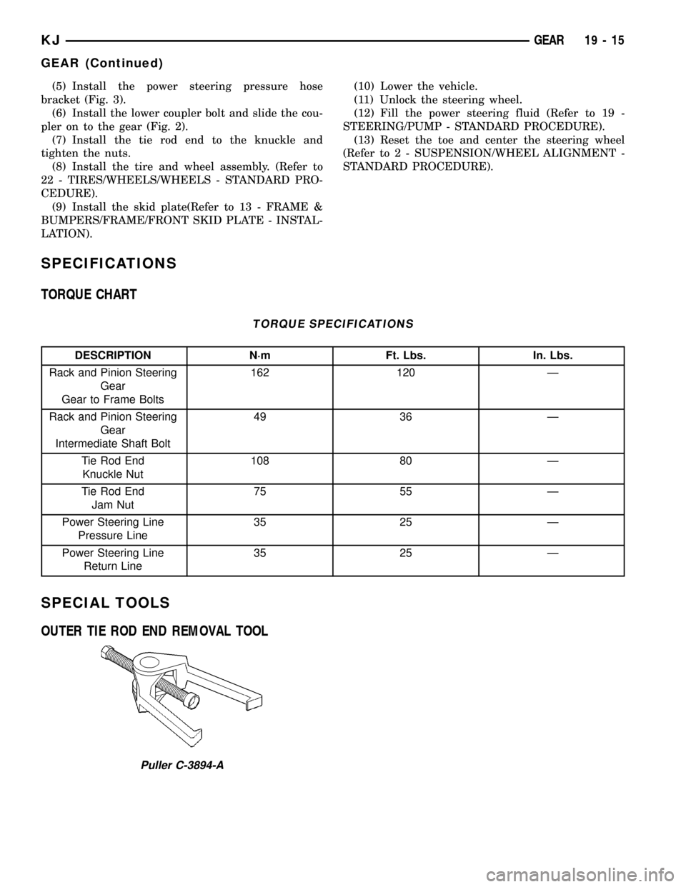
DESCRIPTION N´m Ft. Lbs. In. Lbs.
Rack and Pinion Steering
Gear
Gear to Frame Bolts162 120 Ð
Rack and Pinion Steering
Gear
Intermediate Shaft Bolt49 36 Ð
Tie Rod End
Knuckle Nut108 80 Ð
Tie Rod End
Jam Nut75 55 Ð
Power Steering Line
Pressure Line35 25 Ð
Power Steering Line
Return Line35 25 Ð
SPECIAL TOOLS
OUTER TIE ROD END REMOVAL TOOL
Puller C-3894-A
KJGEAR 19 - 15
GEAR (Continued)
Page 1460 of 1803
TIRES
DESCRIPTION
DESCRIPTION - TIRES
Tires are designed and engineered for each specific
vehicle. They provide the best overall performance
for normal operation. The ride and handling charac-
teristics match the vehicle's requirements. With
proper care they will give excellent reliability, trac-
tion, skid resistance, and tread life.
Driving habits have more effect on tire life than
any other factor. Careful drivers will obtain in most
cases, much greater mileage than severe use or care-
less drivers. A few of the driving habits which will
shorten the life of any tire are:
²Rapid acceleration
²Severe brake applications
²High speed driving
²Excessive speeds on turns
²Striking curbs and other obstacles
Radial-ply tires are more prone to irregular tread
wear. It is important to follow the tire rotation inter-
val,(Refer to 22 - TIRES/WHEELS - STANDARD
PROCEDURE). This will help to achieve a greater
tread life.
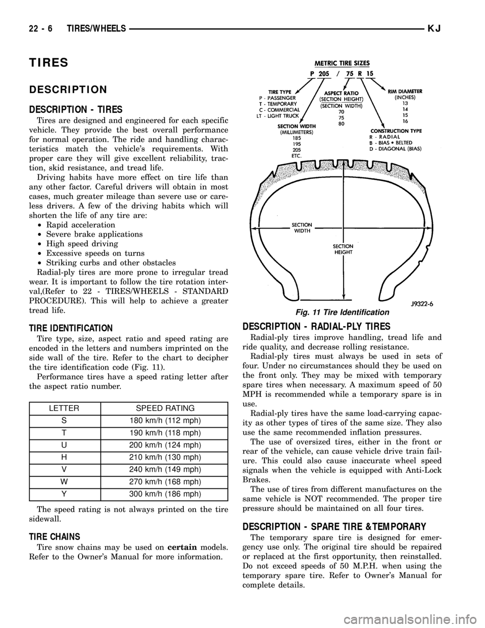
TIRE IDENTIFICATION
Tire type, size, aspect ratio and speed rating are
encoded in the letters and numbers imprinted on the
side wall of the tire. Refer to the chart to decipher
the tire identification code (Fig. 11).
Performance tires have a speed rating letter after
the aspect ratio number.
LETTER SPEED RATING
S 180 km/h (112 mph)
T 190 km/h (118 mph)
U 200 km/h (124 mph)
H 210 km/h (130 mph)
V 240 km/h (149 mph)
W 270 km/h (168 mph)
Y 300 km/h (186 mph)
The speed rating is not always printed on the tire
sidewall.
TIRE CHAINS
Tire snow chains may be used oncertainmodels.
Refer to the Owner's Manual for more information.
DESCRIPTION - RADIAL-PLY TIRES
Radial-ply tires improve handling, tread life and
ride quality, and decrease rolling resistance.
Radial-ply tires must always be used in sets of
four. Under no circumstances should they be used on
the front only. They may be mixed with temporary
spare tires when necessary. A maximum speed of 50
MPH is recommended while a temporary spare is in
use.
Radial-ply tires have the same load-carrying capac-
ity as other types of tires of the same size. They also
use the same recommended inflation pressures.
The use of oversized tires, either in the front or
rear of the vehicle, can cause vehicle drive train fail-
ure. This could also cause inaccurate wheel speed
signals when the vehicle is equipped with Anti-Lock
Brakes.
The use of tires from different manufactures on the
same vehicle is NOT recommended. The proper tire
pressure should be maintained on all four tires.
DESCRIPTION - SPARE TIRE &TEMPORARY
The temporary spare tire is designed for emer-
gency use only. The original tire should be repaired
or replaced at the first opportunity, then reinstalled.
Do not exceed speeds of 50 M.P.H. when using the
temporary spare tire. Refer to Owner's Manual for
complete details.
Fig. 11 Tire Identification
22 - 6 TIRES/WHEELSKJ
Page 1461 of 1803
DESCRIPTION - REPLACEMENT TIRES
The original equipment tires provide a proper bal-
ance of many characteristics such as:
²Ride
²Noise
²Handling
²Durability
²Tread life
²Traction
²Rolling resistance
²Speed capability
It is recommended that tires equivalent to the orig-
inal equipment tires be used when replacement is
needed.
Failure to use equivalent replacement tires may
adversely affect the safety and handling of the vehi-
cle.
The use of oversize tires may cause interference
with vehicle components. Under extremes of suspen-
sion and steering travel, interference with vehicle
components may cause tire damage.
WARNING: FAILURE TO EQUIP THE VEHICLE WITH
TIRES HAVING ADEQUATE SPEED CAPABILITY
CAN RESULT IN SUDDEN TIRE FAILURE.
DIAGNOSIS AND TESTING
DIAGNOSIS AND TESTING - TIRE INFLATION
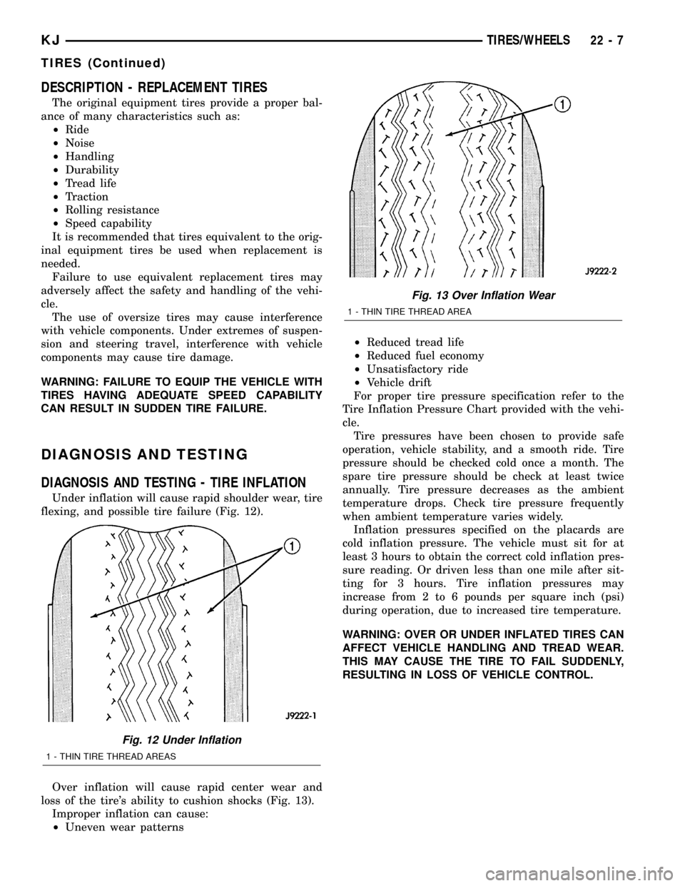
Under inflation will cause rapid shoulder wear, tire
flexing, and possible tire failure (Fig. 12).
Over inflation will cause rapid center wear and
loss of the tire's ability to cushion shocks (Fig. 13).
Improper inflation can cause:
²Uneven wear patterns²Reduced tread life
²Reduced fuel economy
²Unsatisfactory ride
²Vehicle drift
For proper tire pressure specification refer to the
Tire Inflation Pressure Chart provided with the vehi-
cle.
Tire pressures have been chosen to provide safe
operation, vehicle stability, and a smooth ride. Tire
pressure should be checked cold once a month. The
spare tire pressure should be check at least twice
annually. Tire pressure decreases as the ambient
temperature drops. Check tire pressure frequently
when ambient temperature varies widely.
Inflation pressures specified on the placards are
cold inflation pressure. The vehicle must sit for at
least 3 hours to obtain the correct cold inflation pres-
sure reading. Or driven less than one mile after sit-
ting for 3 hours. Tire inflation pressures may
increase from 2 to 6 pounds per square inch (psi)
during operation, due to increased tire temperature.
WARNING: OVER OR UNDER INFLATED TIRES CAN
AFFECT VEHICLE HANDLING AND TREAD WEAR.
THIS MAY CAUSE THE TIRE TO FAIL SUDDENLY,
RESULTING IN LOSS OF VEHICLE CONTROL.
Fig. 12 Under Inflation
1 - THIN TIRE THREAD AREAS
Fig. 13 Over Inflation Wear
1 - THIN TIRE THREAD AREA
KJTIRES/WHEELS 22 - 7
TIRES (Continued)