2002 JEEP LIBERTY tire pressure
[x] Cancel search: tire pressurePage 406 of 1803

perform its many functions. The EMIC module incor-
porates a blue-green digital Vacuum Fluorescent Dis-
play (VFD) for displaying odometer and trip
odometer information, as well as several warning
messages and certain diagnostic information. In addi-
tion to instrumentation and indicators, the EMIC has
the hardware and software needed to provide the fol-
lowing features:
²Chime Warning Service- A chime tone gener-
ator on the EMIC electronic circuit board provides
audible alerts to the vehicle operator and eliminates
the need for a separate chime module. (Refer to 8 -
ELECTRICAL/CHIME WARNING SYSTEM -
DESCRIPTION).
²Panel Lamps Dimming Service- The EMIC
provides a hard wired 12-volt Pulse-Width Modulated
(PWM) output that synchronizes the dimming level
of the radio display, gear selector indicator, heater-air
conditioner control, and all other dimmable lighting
on the panel lamps dimmer circuit with that of the
cluster illumination lamps and VFD.
The EMIC houses four analog gauges and has pro-
visions for up to twenty-four indicators (Fig. 2). The
EMIC includes the following analog gauges:
²Coolant Temperature Gauge
²Fuel Gauge
²Speedometer
²Tachometer
Some of the EMIC indicators are automatically
configured when the EMIC is connected to the vehi-
cle electrical system for compatibility with certain
optional equipment or equipment required for regula-
tory purposes in certain markets. While each EMIC
may have provisions for indicators to support every
available option, the configurable indicators will not
be functional in a vehicle that does not have the
equipment that an indicator supports. The EMIC
includes provisions for the following indicators (Fig.
2):
²Airbag Indicator (with Airbag System only)
²Antilock Brake System (ABS) Indicator
(with ABS only)
²Brake Indicator
²Charging Indicator
²Coolant Low Indicator (with Diesel Engine
only)
²Cruise Indicator (with Speed Control Sys-
tem only)
²Four-Wheel Drive Full Time Indicator (with
Selec-Trac Transfer Case only)
²Four-Wheel Drive Low Mode Indicator
²Four-Wheel Drive Part Time Indicator
²Front Fog Lamp Indicator (with Front Fog
Lamps only)
²High Beam Indicator
²Low Fuel Indicator²Low Oil Pressure Indicator
²Malfunction Indicator Lamp (MIL)
²Overdrive-Off Indicator (with Automatic
Transmission only)
²Rear Fog Lamp Indicator (with Rear Fog
Lamps only)
²Seatbelt Indicator
²Security Indicator (with Vehicle Theft
Security System only)
²Sentry Key Immobilizer System (SKIS)
Indicator (with SKIS only)
²Transmission Overtemp Indicator (with
Automatic Transmission only)
²Turn Signal (Right and Left) Indicators
²Wait-To-Start Indicator (with Diesel Engine
only)
²Water-In-Fuel Indicator (with Diesel Engine
only)
Each indicator in the EMIC is illuminated by a
dedicated Light Emitting Diode (LED) that is sol-
dered onto the EMIC electronic circuit board. The
LEDs are not available for service replacement and,
if damaged or faulty, the entire EMIC must be
replaced. Cluster illumination is accomplished by
dimmable incandescent back lighting, which illumi-
nates the gauges for visibility when the exterior
lighting is turned on. Each of the incandescent bulbs
is secured by an integral bulb holder to the electronic
circuit board from the back of the cluster housing.
The incandescent bulb/bulb holder units are available
for service replacement.
Hard wired circuitry connects the EMIC to the
electrical system of the vehicle. These hard wired cir-
cuits are integral to several wire harnesses, which
are routed throughout the vehicle and retained by
many different methods. These circuits may be con-
nected to each other, to the vehicle electrical system
and to the EMIC through the use of a combination of
soldered splices, splice block connectors, and many
different types of wire harness terminal connectors
and insulators. Refer to the appropriate wiring infor-
mation. The wiring information includes wiring dia-
grams, proper wire and connector repair procedures,
further details on wire harness routing and reten-
tion, as well as pin-out and location views for the
various wire harness connectors, splices and grounds.
The EMIC modules for this model are serviced only
as complete units. The EMIC module cannot be
adjusted or repaired. If a gauge, an LED indicator,
the VFD, the electronic circuit board, the circuit
board hardware, the cluster overlay, or the EMIC
housing are damaged or faulty, the entire EMIC mod-
ule must be replaced. The cluster lens, hood and
mask unit and the individual incandescent lamp
bulbs with holders are available for service replace-
ment.
KJINSTRUMENT CLUSTER 8J - 3
INSTRUMENT CLUSTER (Continued)
Page 486 of 1803
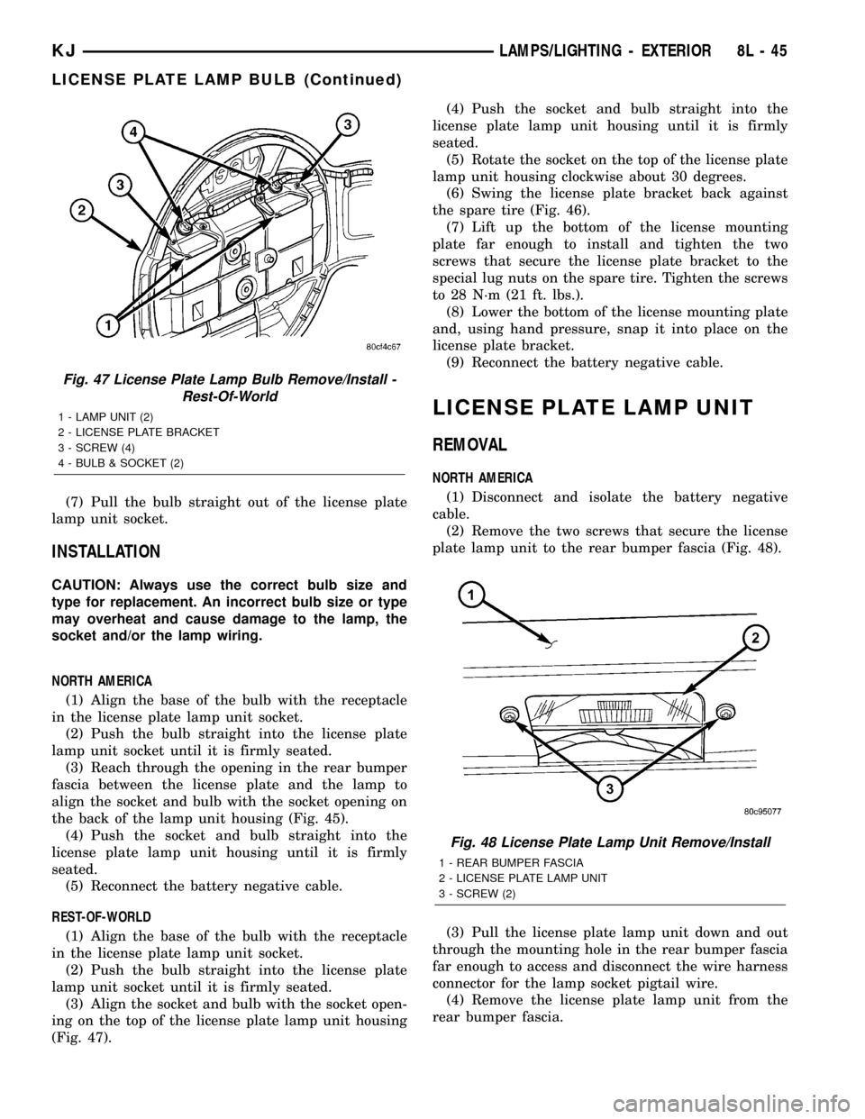
(7) Pull the bulb straight out of the license plate
lamp unit socket.
INSTALLATION
CAUTION: Always use the correct bulb size and
type for replacement. An incorrect bulb size or type
may overheat and cause damage to the lamp, the
socket and/or the lamp wiring.
NORTH AMERICA
(1) Align the base of the bulb with the receptacle
in the license plate lamp unit socket.
(2) Push the bulb straight into the license plate
lamp unit socket until it is firmly seated.
(3) Reach through the opening in the rear bumper
fascia between the license plate and the lamp to
align the socket and bulb with the socket opening on
the back of the lamp unit housing (Fig. 45).
(4) Push the socket and bulb straight into the
license plate lamp unit housing until it is firmly
seated.
(5) Reconnect the battery negative cable.
REST-OF-WORLD
(1) Align the base of the bulb with the receptacle
in the license plate lamp unit socket.
(2) Push the bulb straight into the license plate
lamp unit socket until it is firmly seated.
(3) Align the socket and bulb with the socket open-
ing on the top of the license plate lamp unit housing
(Fig. 47).(4) Push the socket and bulb straight into the
license plate lamp unit housing until it is firmly
seated.
(5) Rotate the socket on the top of the license plate
lamp unit housing clockwise about 30 degrees.
(6) Swing the license plate bracket back against
the spare tire (Fig. 46).
(7) Lift up the bottom of the license mounting
plate far enough to install and tighten the two
screws that secure the license plate bracket to the
special lug nuts on the spare tire. Tighten the screws
to 28 N´m (21 ft. lbs.).
(8) Lower the bottom of the license mounting plate
and, using hand pressure, snap it into place on the
license plate bracket.
(9) Reconnect the battery negative cable.
LICENSE PLATE LAMP UNIT
REMOVAL
NORTH AMERICA
(1) Disconnect and isolate the battery negative
cable.
(2) Remove the two screws that secure the license
plate lamp unit to the rear bumper fascia (Fig. 48).
(3) Pull the license plate lamp unit down and out
through the mounting hole in the rear bumper fascia
far enough to access and disconnect the wire harness
connector for the lamp socket pigtail wire.
(4) Remove the license plate lamp unit from the
rear bumper fascia.
Fig. 47 License Plate Lamp Bulb Remove/Install -
Rest-Of-World
1 - LAMP UNIT (2)
2 - LICENSE PLATE BRACKET
3 - SCREW (4)
4 - BULB & SOCKET (2)
Fig. 48 License Plate Lamp Unit Remove/Install
1 - REAR BUMPER FASCIA
2 - LICENSE PLATE LAMP UNIT
3 - SCREW (2)
KJLAMPS/LIGHTING - EXTERIOR 8L - 45
LICENSE PLATE LAMP BULB (Continued)
Page 570 of 1803
INSTALLATION
CAUTION: Always use the correct bulb size and
type for replacement. An incorrect bulb size or type
may overheat and cause damage to the lamp, the
socket and/or the lamp wiring.
NORTH AMERICA
(1) Align the base of the bulb with the receptacle
in the license plate lamp unit socket.
(2) Push the bulb straight into the license plate
lamp unit socket until it is firmly seated.
(3) Reach through the opening in the rear bumper
fascia between the license plate and the lamp to
align the socket and bulb with the socket opening on
the back of the lamp unit housing (Fig. 45).
(4) Push the socket and bulb straight into the
license plate lamp unit housing until it is firmly
seated.
(5) Reconnect the battery negative cable.
REST-OF-WORLD
(1) Align the base of the bulb with the receptacle
in the license plate lamp unit socket.
(2) Push the bulb straight into the license plate
lamp unit socket until it is firmly seated.
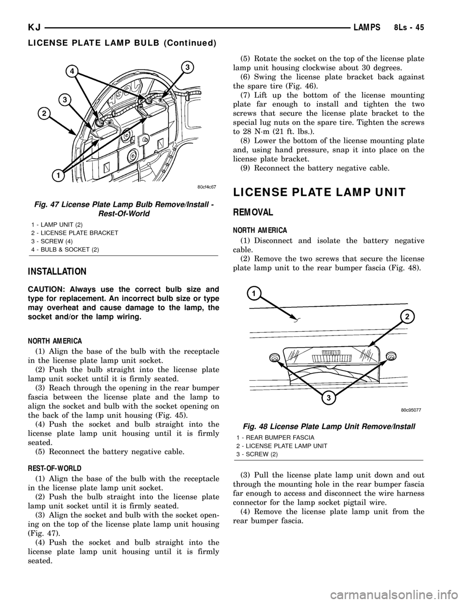
(3) Align the socket and bulb with the socket open-
ing on the top of the license plate lamp unit housing
(Fig. 47).
(4) Push the socket and bulb straight into the
license plate lamp unit housing until it is firmly
seated.(5) Rotate the socket on the top of the license plate
lamp unit housing clockwise about 30 degrees.
(6) Swing the license plate bracket back against
the spare tire (Fig. 46).
(7) Lift up the bottom of the license mounting
plate far enough to install and tighten the two
screws that secure the license plate bracket to the
special lug nuts on the spare tire. Tighten the screws
to 28 N´m (21 ft. lbs.).
(8) Lower the bottom of the license mounting plate
and, using hand pressure, snap it into place on the
license plate bracket.
(9) Reconnect the battery negative cable.
LICENSE PLATE LAMP UNIT
REMOVAL
NORTH AMERICA
(1) Disconnect and isolate the battery negative
cable.
(2) Remove the two screws that secure the license
plate lamp unit to the rear bumper fascia (Fig. 48).
(3) Pull the license plate lamp unit down and out
through the mounting hole in the rear bumper fascia
far enough to access and disconnect the wire harness
connector for the lamp socket pigtail wire.
(4) Remove the license plate lamp unit from the
rear bumper fascia.
Fig. 47 License Plate Lamp Bulb Remove/Install -
Rest-Of-World
1 - LAMP UNIT (2)
2 - LICENSE PLATE BRACKET
3 - SCREW (4)
4 - BULB & SOCKET (2)
Fig. 48 License Plate Lamp Unit Remove/Install
1 - REAR BUMPER FASCIA
2 - LICENSE PLATE LAMP UNIT
3 - SCREW (2)
KJLAMPS8Ls-45
LICENSE PLATE LAMP BULB (Continued)
Page 738 of 1803
INSTALLATION
NOTE: The rear washer nozzle latch feature is a one
time component, and will be damaged if the nozzle
is removed from its mounting hole for service. If
removed from its mounting hole for any reason, the
rear washer nozzle must be replaced with a new
unit.
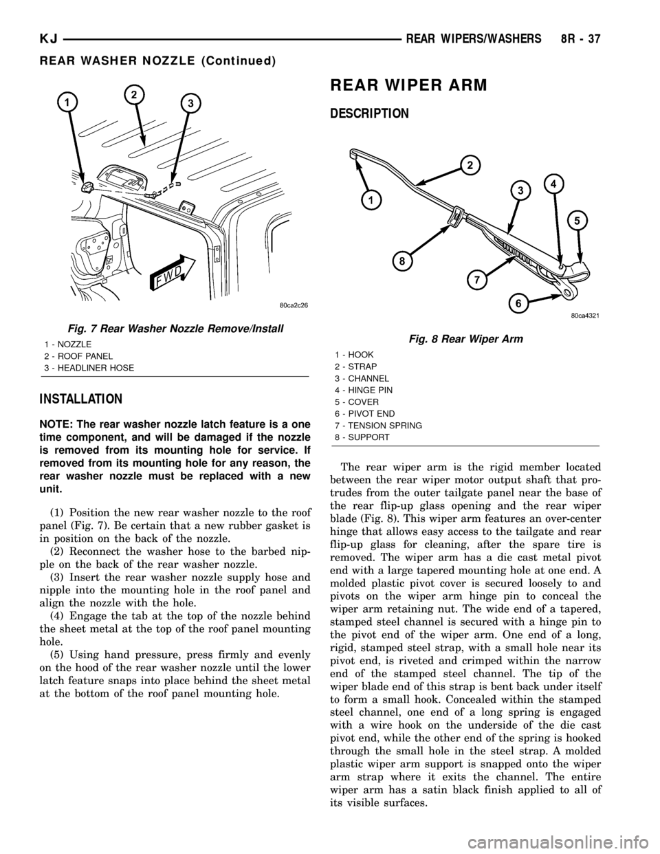
(1) Position the new rear washer nozzle to the roof
panel (Fig. 7). Be certain that a new rubber gasket is
in position on the back of the nozzle.
(2) Reconnect the washer hose to the barbed nip-
ple on the back of the rear washer nozzle.
(3) Insert the rear washer nozzle supply hose and
nipple into the mounting hole in the roof panel and
align the nozzle with the hole.
(4) Engage the tab at the top of the nozzle behind
the sheet metal at the top of the roof panel mounting
hole.
(5) Using hand pressure, press firmly and evenly
on the hood of the rear washer nozzle until the lower
latch feature snaps into place behind the sheet metal
at the bottom of the roof panel mounting hole.
REAR WIPER ARM
DESCRIPTION
The rear wiper arm is the rigid member located
between the rear wiper motor output shaft that pro-
trudes from the outer tailgate panel near the base of
the rear flip-up glass opening and the rear wiper
blade (Fig. 8). This wiper arm features an over-center
hinge that allows easy access to the tailgate and rear
flip-up glass for cleaning, after the spare tire is
removed. The wiper arm has a die cast metal pivot
end with a large tapered mounting hole at one end. A
molded plastic pivot cover is secured loosely to and
pivots on the wiper arm hinge pin to conceal the
wiper arm retaining nut. The wide end of a tapered,
stamped steel channel is secured with a hinge pin to
the pivot end of the wiper arm. One end of a long,
rigid, stamped steel strap, with a small hole near its
pivot end, is riveted and crimped within the narrow
end of the stamped steel channel. The tip of the
wiper blade end of this strap is bent back under itself
to form a small hook. Concealed within the stamped
steel channel, one end of a long spring is engaged
with a wire hook on the underside of the die cast
pivot end, while the other end of the spring is hooked
through the small hole in the steel strap. A molded
plastic wiper arm support is snapped onto the wiper
arm strap where it exits the channel. The entire
wiper arm has a satin black finish applied to all of
its visible surfaces.
Fig. 7 Rear Washer Nozzle Remove/Install
1 - NOZZLE
2 - ROOF PANEL
3 - HEADLINER HOSEFig. 8 Rear Wiper Arm
1 - HOOK
2 - STRAP
3 - CHANNEL
4 - HINGE PIN
5 - COVER
6 - PIVOT END
7 - TENSION SPRING
8 - SUPPORT
KJREAR WIPERS/WASHERS 8R - 37
REAR WASHER NOZZLE (Continued)
Page 1265 of 1803
90É turn. DO NOT rotate crankshaft. Plastigage will
smear, resulting in inaccurate indication.
(6) Remove the bearing cap and determine amount
of bearing-to-journal clearance by measuring the
width of compressed Plastigage. Refer to Engine
Specifications for the proper clearance.Plastigage
should indicate the same clearance across the
entire width of the insert. If the clearance var-
ies, it may be caused by either a tapered jour-
nal, bent connecting rod or foreign material
trapped between the insert and cap or rod.
(7) If the correct clearance is indicated, replace-
ment of the bearing inserts is not necessary. Remove
the Plastigage from crankshaft journal and bearing
insert. Proceed with installation.
(8) If bearing-to-journal clearance exceeds the
specification, determin which services bearing set to
use the bearing sizes are as follows:
Bearing
MarkSIZE USED WITH
JOURNAL SIZE
.025 US.025 mm 57.871-57.879 mm
(.001 in.) (2.2783-2.2786 in.)
Std.STANDARD 57.896-57.904 mm
(2.2793-2.2810 in.)
.250 US.250 mm 57.646-57.654 mm
(.010 in.) (2.2695-2.2698 in.)
(9) Repeat the Plastigage measurement to verify
your bearing selection prior to final assembly.
(10) Once you have selected the proper insert,
install the insert and cap. Tighten the connecting rod
bolts to 27 N´m (20 ft. lbs.) plus a 90É turn.
Slide snug-fitting feeler gauge between the con-
necting rod and crankshaft journal flange. Refer to
Engine Specifications for the proper clearance.
Replace the connecting rod if the side clearance is
not within specification.
STANDARD PROCEDURE - PISTON FITTING
(1) To correctly select the proper size piston, a cyl-
inder bore gauge, capable of reading in 0.003 mm (
.0001 in.) INCREMENTS is required. If a bore gauge
is not available, do not use an inside micrometer.
(2) Measure the inside diameter of the cylinder
bore at a point 38.0 mm (1.5 inches) below top of
bore. Start perpendicular (across or at 90 degrees) to
the axis of the crankshaft at point A and then take
an additional bore reading 90 degrees to that at point
B (Fig. 54).
(3) The coated pistons will be serviced with the
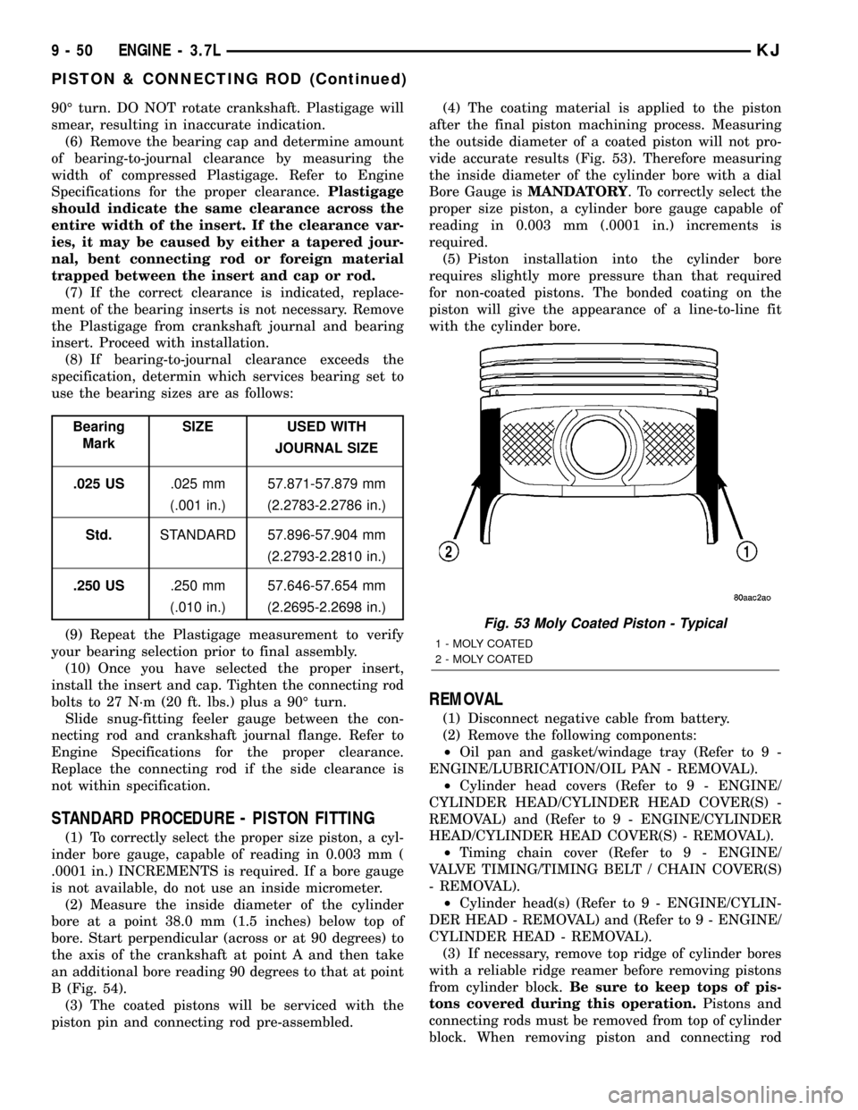
piston pin and connecting rod pre-assembled.(4) The coating material is applied to the piston
after the final piston machining process. Measuring
the outside diameter of a coated piston will not pro-
vide accurate results (Fig. 53). Therefore measuring
the inside diameter of the cylinder bore with a dial
Bore Gauge isMANDATORY. To correctly select the
proper size piston, a cylinder bore gauge capable of
reading in 0.003 mm (.0001 in.) increments is
required.
(5) Piston installation into the cylinder bore
requires slightly more pressure than that required
for non-coated pistons. The bonded coating on the
piston will give the appearance of a line-to-line fit
with the cylinder bore.
REMOVAL
(1) Disconnect negative cable from battery.
(2) Remove the following components:
²Oil pan and gasket/windage tray (Refer to 9 -
ENGINE/LUBRICATION/OIL PAN - REMOVAL).
²Cylinder head covers (Refer to 9 - ENGINE/
CYLINDER HEAD/CYLINDER HEAD COVER(S) -
REMOVAL) and (Refer to 9 - ENGINE/CYLINDER
HEAD/CYLINDER HEAD COVER(S) - REMOVAL).
²Timing chain cover (Refer to 9 - ENGINE/
VALVE TIMING/TIMING BELT / CHAIN COVER(S)
- REMOVAL).
²Cylinder head(s) (Refer to 9 - ENGINE/CYLIN-
DER HEAD - REMOVAL) and (Refer to 9 - ENGINE/
CYLINDER HEAD - REMOVAL).
(3) If necessary, remove top ridge of cylinder bores
with a reliable ridge reamer before removing pistons
from cylinder block.Be sure to keep tops of pis-
tons covered during this operation.Pistons and
connecting rods must be removed from top of cylinder
block. When removing piston and connecting rod
Fig. 53 Moly Coated Piston - Typical
1 - MOLY COATED
2 - MOLY COATED
9 - 50 ENGINE - 3.7LKJ
PISTON & CONNECTING ROD (Continued)
Page 1275 of 1803
DIAGNOSIS AND TESTING
DIAGNOSIS AND TESTING - ENGINE OIL LEAK
Begin with a thorough visual inspection of the
engine, particularly at the area of the suspected leak.
If an oil leak source is not readily identifiable, the
following steps should be followed:
(1) Do not clean or degrease the engine at this
time because some solvents may cause rubber to
swell, temporarily stopping the leak.
(2) Add an oil soluble dye (use as recommended by
manufacturer). Start the engine and let idle for
approximately 15 minutes. Check the oil dipstick to
make sure the dye is thoroughly mixed as indicated
with a bright yellow color under a black light.
(3) Using a black light, inspect the entire engine
for fluorescent dye, particularly at the suspected area
of oil leak. If the oil leak is found and identified,
repair per service manual instructions.
(4) If dye is not observed, drive the vehicle at var-
ious speeds for approximately 24km (15 miles), and
repeat inspection.If the oil leak source is not pos-
itively identified at this time, proceed with the air
leak detection test method.
Air Leak Detection Test Method
(1) Disconnect the breather cap to air cleaner hose
at the breather cap end. Cap or plug breather cap
nipple.
(2) Remove the PCV valve from the cylinder head
cover. Cap or plug the PCV valve grommet.
(3) Attach an air hose with pressure gauge and
regulator to the dipstick tube.
CAUTION: Do not subject the engine assembly to
more than 20.6 kpa (3 PSI) of test pressure.
(4) Gradually apply air pressure from 1 psi to 2.5
psi maximum while applying soapy water at the sus-
pected source. Adjust the regulator to the suitable
test pressure that provide the best bubbles which
will pinpoint the leak source. If the oil leak is
detected and identified, repair per service manual
procedures.
(5) If the leakage occurs at the rear oil seal area,
refer to the section, Inspection for Rear Seal Area
Leak.
(6) If no leaks are detected, turn off the air supply
and remove the air hose and all plugs and caps.
Install the PCV valve and breather cap hose.
(7) Clean the oil off the suspect oil leak area using
a suitable solvent. Drive the vehicle at various
speeds approximately 24 km (15 miles). Inspect the
engine for signs of an oil leak by using a black light.
INSPECTION FOR REAR SEAL AREA LEAKS
Since it is sometimes difficult to determine the
source of an oil leak in the rear seal area of the
engine, a more involved inspection is necessary. The
following steps should be followed to help pinpoint
the source of the leak.
If the leakage occurs at the crankshaft rear oil seal
area:
(1) Disconnect the battery.
(2) Raise the vehicle.
(3) Remove torque converter or clutch housing
cover and inspect rear of block for evidence of oil.
Use a black light to check for the oil leak:
(a) Circular spray pattern generally indicates
seal leakage or crankshaft damage.
(b) Where leakage tends to run straight down,
possible causes are a porous block, camshaft bore
cup plugs oil galley pipe plugs, oil filter runoff, and
main bearing cap to cylinder block mating sur-
faces.
(4) If no leaks are detected, pressurize the crank-
case as outlined in the, Inspection (Engine oil Leaks
in general)
CAUTION: Do not exceed 20.6 kPa (3 psi).
(5) If the leak is not detected, very slowly turn the
crankshaft and watch for leakage. If a leak is
detected between the crankshaft and seal while
slowly turning the crankshaft, it is possible the
crankshaft seal surface is damaged. The seal area on
the crankshaft could have minor nicks or scratches
that can be polished out with emery cloth.
CAUTION: Use extreme caution when crankshaft
polishing is necessary to remove minor nicks and
scratches. The crankshaft seal flange is especially
machined to complement the function of the rear oil
seal.
(6) For bubbles that remain steady with shaft
rotation, no further inspection can be done until dis-
assembled.
DIAGNOSIS AND TESTING - ENGINE OIL
PRESSURE
(1) Remove oil pressure sending unit (Fig. 70)and
install gauge assembly C-3292.
(2) Run engine until thermostat opens.
(3) Oil Pressure:
²Curb IdleÐ25 Kpa (4 psi) minimum
²3000 rpmÐ170 - 550 KPa (25 - 80 psi)
(4) If oil pressure is 0 at idle, shut off engine.
Check for a clogged oil pick-up screen or a pressure
relief valve stuck open.
9 - 60 ENGINE - 3.7LKJ
LUBRICATION (Continued)
Page 1281 of 1803
INSPECTION
CAUTION: Oil pump pressure relief valve and
spring should not be removed from the oil pump. If
these components are disassembled and or
removed from the pump the entire oil pump assem-
bly must be replaced.
(1) Clean all parts thoroughly. Mating surface of
the oil pump housing should be smooth. If the pump
cover is scratched or grooved the oil pump assembly
should be replaced.
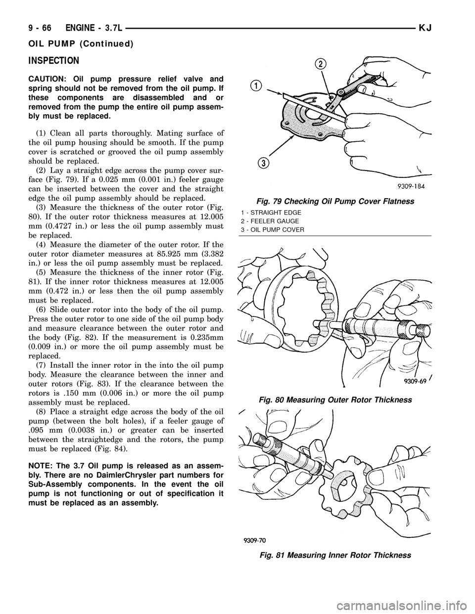
(2) Lay a straight edge across the pump cover sur-
face (Fig. 79). If a 0.025 mm (0.001 in.) feeler gauge
can be inserted between the cover and the straight
edge the oil pump assembly should be replaced.
(3) Measure the thickness of the outer rotor (Fig.
80). If the outer rotor thickness measures at 12.005
mm (0.4727 in.) or less the oil pump assembly must
be replaced.
(4) Measure the diameter of the outer rotor. If the
outer rotor diameter measures at 85.925 mm (3.382
in.) or less the oil pump assembly must be replaced.
(5) Measure the thickness of the inner rotor (Fig.
81). If the inner rotor thickness measures at 12.005
mm (0.472 in.) or less then the oil pump assembly
must be replaced.
(6) Slide outer rotor into the body of the oil pump.
Press the outer rotor to one side of the oil pump body
and measure clearance between the outer rotor and
the body (Fig. 82). If the measurement is 0.235mm
(0.009 in.) or more the oil pump assembly must be
replaced.
(7) Install the inner rotor in the into the oil pump
body. Measure the clearance between the inner and
outer rotors (Fig. 83). If the clearance between the
rotors is .150 mm (0.006 in.) or more the oil pump
assembly must be replaced.
(8) Place a straight edge across the body of the oil
pump (between the bolt holes), if a feeler gauge of
.095 mm (0.0038 in.) or greater can be inserted
between the straightedge and the rotors, the pump
must be replaced (Fig. 84).
NOTE: The 3.7 Oil pump is released as an assem-
bly. There are no DaimlerChrysler part numbers for
Sub-Assembly components. In the event the oil
pump is not functioning or out of specification it
must be replaced as an assembly.
Fig. 79 Checking Oil Pump Cover Flatness
1 - STRAIGHT EDGE
2 - FEELER GAUGE
3 - OIL PUMP COVER
Fig. 80 Measuring Outer Rotor Thickness
Fig. 81 Measuring Inner Rotor Thickness
9 - 66 ENGINE - 3.7LKJ
OIL PUMP (Continued)
Page 1301 of 1803
(7) Crank engine until maximum pressure is
reached on gage. Record this pressure as #1 cylinder
pressure.
(8) Repeat the previous step for all remaining cyl-
inders.
(9) Compression should not be less than 689 kPa
(100 psi) and not vary more than 25 percent from cyl-
inder to cylinder.
(10) If one or more cylinders have abnormally low
compression pressures, repeat the compression test.
(11) If the same cylinder or cylinders repeat an
abnormally low reading on the second compression
test, it could indicate the existence of a problem in
the cylinder in question.The recommended com-
pression pressures are to be used only as a
guide to diagnosing engine problems. An engine
should not be disassembled to determine the
cause of low compression unless some malfunc-
tion is present.
DIAGNOSIS AND TESTING - ENGINE OIL LEAK
INSPECTION
Begin with a thorough visual inspection of the
engine, particularly at the area of the suspected leak.
If an oil leak source is not readily identifiable, the
following steps should be followed:
(1) Do not clean or degrease the engine at this
time because some solvents may cause rubber to
swell, temporarily stopping the leak.
(2) Add an oil soluble dye (use as recommended by
manufacturer). Start the engine and let idle for
approximately 15 minutes. Check the oil dipstick to
make sure the dye is thoroughly mixed as indicated
with a bright yellow color under a black light.
(3) Using a black light, inspect the entire engine
for fluorescent dye, particularly at the suspected area
of oil leak. If the oil leak is found and identified,
repair as necessary.
(4) If dye is not observed, drive the vehicle at var-
ious speeds for approximately 24 km (15 miles), and
repeat inspection.
(5)If the oil leak source is not positively
identified at this time, proceed with the air leak
detection test method as follows:
²Disconnect the fresh air hose (make-up air) at
the cylinder head cover and plug or cap the nipple on
the cover.
²Remove the PCV valve hose from the cylinder
head cover. Cap or plug the PCV valve nipple on the
cover.
²Attach an air hose with pressure gauge and reg-
ulator to the dipstick tube.
CAUTION: Do not subject the engine assembly to
more than 20.6 kpa (3 PSI) of test pressure.²Gradually apply air pressure from 1 psi to 2.5
psi maximum while applying soapy water at the sus-
pected source. Adjust the regulator to the suitable
test pressure that provides the best bubbles which
will pinpoint the leak source. If the oil leak is
detected and identified, repair per service manual
procedures.
²If the leakage occurs at the crankshaft rear oil
seal area, refer to the section, Inspection for Rear
Seal Area Leak.
(6) If no leaks are detected, turn off the air supply.
Remove the air hose, all plugs, and caps. Install the
PCV valve and fresh air hose (make-up air). Proceed
to next step.
(7) Clean the oil off the suspect oil leak area using
a suitable solvent. Drive the vehicle at various
speeds approximately 24 km (15 miles). Inspect the
engine for signs of an oil leak by using a black light.
NOTE: If oil leakage is observed at the dipstick tube
to block location; remove the tube, clean and reseal
using MoparTStud & Bearing Mount (press fit tube
applications only), and for O-ring style tubes,
remove tube and replace the O-ring seal.
INSPECTION FOR REAR SEAL AREA LEAKS
Since it is sometimes difficult to determine the
source of an oil leak in the rear seal area of the
engine, a more involved inspection is necessary. The
following steps should be followed to help pinpoint
the source of the leak.
If the leakage occurs at the crankshaft rear oil seal
area:
(1) Disconnect the battery.
(2) Raise the vehicle.
(3) Remove torque converter or clutch housing
cover and inspect rear of block for evidence of oil.
Use a black light to check for the oil leak. If a leak is
present in this area, remove transmission for further
inspection.
(a) Circular spray pattern generally indicates
seal leakage or crankshaft damage.
(b) Where leakage tends to run straight down,
possible causes are a porous block, oil gallery cup
plug, bedplate to cylinder block mating surfaces
and seal bore. See proper repair procedures for
these items.
(4) If no leaks are detected, pressurize the crank-
case as previously described.
CAUTION: Do not exceed 20.6 kPa (3 psi).
(5) If the leak is not detected, very slowly turn the
crankshaft and watch for leakage. If a leak is
detected between the crankshaft and seal while
slowly turning the crankshaft, it is possible the
9s - 4 ENGINEKJ
ENGINE - 2.4L (Continued)