2002 JEEP LIBERTY Change JB
[x] Cancel search: Change JBPage 1286 of 1803
(1) Position the engine exhaust manifold and gas-
ket on the two studs located on the cylinder head.
Install conical washers and nuts on these studs.
(2) Install remaining conical washers. Starting at
the center arm and working outward, tighten the
bolts and nuts to 25 N´m (18 ft. lbs.) torque.
(3) Install the exhaust heat shields.
(4) Raise and support the vehicle.
CAUTION: Over tightening heat shield fasteners,
may cause shield to distort and/or crack.
(5) Assemble exhaust pipe to manifold and secure
with bolts, nuts and retainers. Tighten the bolts and
nuts to 34 N´m (25 ft. lbs.) torque.
LEFT EXHAUST MANIFOLD
CAUTION: If the studs came out with the nuts when
removing the engine exhaust manifold, install new
studs. Apply sealer on the coarse thread ends.
Water leaks may develop at the studs if this precau-
tion is not taken.
(1) Position the engine exhaust manifold and gas-
ket on the two studs located on the cylinder head.
Install conical washers and nuts on these studs.
(2) Install remaining conical washers. Starting at
the center arm and working outward, tighten the
bolts and nuts to 25 N´m (18 ft. lbs.) torque.
(3) Install the exhaust heat shields.
(4) Raise and support the vehicle.
CAUTION: Over tightening heat shield fasteners,
may cause shield to distort and/or crack.
(5) Assemble exhaust pipe to manifold and secure
with bolts, nuts and retainers. Tighten the bolts and
nuts to 34 N´m (25 ft. lbs.) torque.
VALVE TIMING
DESCRIPTION
The timing drive system has been designed to pro-
vide quiet performance and reliability to support a
non-free wheelingengine. Specifically the intake
valves are non-free wheeling and can be easily dam-
aged with forceful engine rotation if camshaft-to-
crankshaft timing is incorrect. The timing drive
system consists of a primary chain, two secondary
timing chain drives and a counterbalance shaft drive.
OPERATION
The primary timing chain is a single inverted tooth
chain type. The primary chain drives the large 40
tooth idler sprocket directly from a 20 tooth crank-shaft sprocket. Primary chain motion is controlled by
a pivoting leaf spring tensioner arm and a fixed
guide. The arm and the guide both use nylon plastic
wear faces for low friction and long wear. The pri-
mary chain receives oil splash lubrication from the
secondary chain drive and designed oil pump leak-
age. The idler sprocket assembly connects the pri-
mary chain drive, secondary chain drives, and the
counterbalance shaft. The idler sprocket assembly
consists of two integral 26 tooth sprockets a 40 tooth
sprocket and a helical gear that is press-fit to the
assembly. The spline joint for the 40 tooth sprocket is
a non ± serviceable press fit anti rattle type. A spiral
ring is installed on the outboard side of the fifty
tooth sprocket to prevent spline disengagement. The
idler sprocket assembly spins on a stationary idler
shaft. The idler shaft is a light press-fit into the cyl-
inder block. A large washer on the idler shaft bolt
and the rear flange of the idler shaft are used to con-
trol sprocket thrust movement. Pressurized oil is
routed through the center of the idler shaft to pro-
vide lubrication for the two bushings used in the
idler sprocket assembly.
There are two secondary drive chains, both are
roller type, one to drive the camshaft in each SOHC
cylinder head. There are no shaft speed changes in
the secondary chain drive system. Each secondary
chain drives a 26 tooth cam sprocket directly from
the 26 tooth sprocket on the idler sprocket assembly.
A fixed chain guide and a hydraulic oil damped ten-
sioner are used to maintain tension in each second-
ary chain system. The hydraulic tensioners for the
secondary chain systems are fed pressurized oil from
oil reservoir pockets in the block. Each tensioner
incorprates a controled leak path through a device
known as a vent disc located in the nose of the piston
to manage chain loads. Each tensioner also has a
mechanical ratchet system that limits chain slack if
the tensioner piston bleeds down after engine shut
down. The tensioner arms and guides also utilize
nylon wear faces for low friction and long wear. The
secondary timing chains receive lubrication from a
small orifice in the tensioners. This orifice is pro-
tected from clogging by a fine mesh screen which is
located on the back of the hydraulic tensioners.
STANDARD PROCEDURE
MEASURING TIMING CHAIN WEAR
NOTE: This procedure must be performed with the
timing chain cover removed.
(1) Remove the timing chain cover. Refer to Timing
Chain Cover in this section for procedure.
KJENGINE - 3.7L 9 - 71
EXHAUST MANIFOLD (Continued)
Page 1299 of 1803
CRANKSHAFT
DESCRIPTION.........................32
OPERATION...........................33
STANDARD PROCEDURE - CRANKSHAFT
ENDPLAY ...........................33
REMOVAL.............................33
INSPECTION..........................34
INSTALLATION.........................34
CRANKSHAFT MAIN BEARINGS
STANDARD PROCEDURE - MAIN BEARING -
FITTING.............................35
CRANKSHAFT OIL SEAL - FRONT
REMOVAL.............................37
INSTALLATION.........................37
CRANKSHAFT OIL SEAL - REAR
REMOVAL.............................38
INSTALLATION.........................39
PISTON & CONNECTING ROD
DESCRIPTION.........................40
OPERATION...........................40
REMOVAL.............................40
INSTALLATION.........................41
PISTON RINGS
STANDARD PROCEDURE
PISTON RING - FITTING................42
VIBRATION DAMPER
REMOVAL.............................43
INSTALLATION.........................43
STRUCTURAL COLLAR
REMOVAL.............................44
INSTALLATION.........................44
ENGINE MOUNTING
DESCRIPTION.........................44
FRONT MOUNT
REMOVAL.............................44
INSTALLATION.........................44
REAR MOUNT
REMOVAL.............................45
INSTALLATION.........................45
LUBRICATION
DESCRIPTION.........................46
OPERATION...........................46
DIAGNOSIS AND TESTING - ENGINE OIL
PRESSURE CHECKING.................46
OIL
STANDARD PROCEDURE
ENGINE OIL LEVEL CHECK.............47
STANDARD PROCEDURE - ENGINE OIL
AND FILTER CHANGE..................47
OIL FILTER
DESCRIPTION.........................47
REMOVAL.............................47
INSTALLATION.........................47
OIL PAN
REMOVAL.............................48INSTALLATION.........................48
OIL PRESSURE SENSOR/SWITCH
DESCRIPTION.........................48
OPERATION...........................48
OIL PUMP
REMOVAL.............................49
DISASSEMBLY.........................49
CLEANING............................49
INSPECTION..........................50
ASSEMBLY............................50
INSTALLATION.........................50
INTAKE MANIFOLD
DESCRIPTION.........................51
OPERATION...........................51
DIAGNOSIS AND TESTING - INTAKE
MANIFOLD LEAKS.....................51
REMOVAL.............................52
INSPECTION..........................52
INSTALLATION.........................52
EXHAUST MANIFOLD
DESCRIPTION.........................53
OPERATION...........................53
REMOVAL.............................53
CLEANING............................53
INSPECTION..........................53
INSTALLATION.........................53
TIMING BELT COVER(S)
REMOVAL.............................53
INSTALLATION.........................53
TIMING BELT AND SPROCKET(S)
REMOVAL
REMOVAL - TIMING BELT...............55
REMOVAL - CRANKSHAFT SPROCKET....55
CLEANING............................55
INSTALLATION
INSTALLATION - CRANKSHAFT SPROCKET . 56
INSTALLATION - TIMING BELT...........56
TIMING BELT TENSIONER & PULLEY
REMOVAL.............................59
INSTALLATION.........................59
BALANCE SHAFT
DESCRIPTION.........................59
OPERATION...........................59
REMOVAL.............................60
INSTALLATION
BALANCE SHAFT TIMING...............61
BALANCE SHAFT CARRIER
REMOVAL.............................64
INSTALLATION.........................64
BALANCE SHAFT CHAIN
REMOVAL.............................64
INSTALLATION.........................64
9s - 2 ENGINEKJ
Page 1304 of 1803
DIAGNOSIS AND TESTING - ENGINE MECHANICAL
CONDITION POSSIBLE CAUSES CORRECTION
NOISY VALVES 1. High or low oil level in
crankcase.1. Check and correct engine oil
level.
2. Thin or diluted oil. 2. Change oil to correct viscosity.
3. Thick oil 3. (a) Change engine oil and filter.
(b) Run engine to operating
temperature.
(c) Change engine oil and filter
again.
4. Low oil pressure. 4. Check and correct engine oil
level.
5. Dirt in tappets/lash adjusters. 5. Replace rocker arm/hydraulic
lash adjuster assembly.
6. Worn rocker arms. 6. Inspect oil supply to rocker arms.
7. Worn tappets/lash adjusters. 7. Install new rocker arm/hydraulic
lash adjuster assembly.
8. Worn valve guides. 8. Replace cylinder head assembly.
9. Excessive runout of valve seats
on valve faces.9. Grind valve seats and valves.
10. Missing adjuster pivot. 10. Replace rocker arm/hydraulic
lash adjuster assembly.
CONNECTING ROD NOISE 1. Insufficient oil supply. 1. Check engine oil level.
2. Low oil pressure. 2. Check engine oil level. Inspect oil
pump relief valve and spring.
3. Thin or diluted oil. 3. Change oil to correct viscosity.
4. Thick oil 4. (a) Change engine oil and filter.
(b) Run engine to operating
temperature.
(c) Change engine oil and filter
again.
5. Excessive bearing clearance. 5. Measure bearings for correct
clearance. Repair as necessary.
6. Connecting rod journal
out-of-round.6. Replace crankshaft or grind
surface.
7. Misaligned connecting rods. 7. Replace bent connecting rods.
KJENGINE9s-7
ENGINE - 2.4L (Continued)
Page 1305 of 1803
CONDITION POSSIBLE CAUSES CORRECTION
MAIN BEARING NOISE 1. Insufficient oil supply. 1. Check engine oil level.
2. Low oil pressure. 2. Check engine oil level. Inspect oil
pump relief valve and spring.
3. Thin or diluted oil. 3. Change oil to correct viscosity.
4. Thick oil 4. (a) Change engine oil and filter.
(b) Run engine to operating
temperature.
(c) Change engine oil and filter
again.
5. Excessive bearing clearance. 5. Measure bearings for correct
clearance. Repair as necessary.
6. Excessive end play. 6. Check thrust bearing for wear on
flanges.
7. Crankshaft journal out-of-round
or worn.7. Replace crankshaft or grind
journals.
8. Loose flywheel or torque
converter.8. Tighten to correct torque.
OIL PRESSURE DROP 1. Low oil level. 1. Check engine oil level.
2. Faulty oil pressure sending unit. 2. Install new sending unit.
3. Low oil pressure. 3. Check sending unit and main
bearing oil clearance.
4. Clogged oil filter. 4. Install new oil filter.
5. Worn parts in oil pump. 5. Replace worn parts or pump.
6. Thin or diluted oil. 6. Change oil to correct viscosity.
7. Oil pump relief valve stuck. 7. Replace oil pump.
8. Oil pump suction tube loose. 8. Remove oil pan and install new
tube or clean, if necessary.
9. Oil pump cover warped or
cracked.9. Install new oil pump.
10. Excessive bearing clearance. 10. Measure bearings for correct
clearance.
OIL LEAKS 1. Misaligned or deteriorated
gaskets.1. Replace gasket(s).
2. Loose fastener, broken or porous
metal part.2. Tighten, repair or replace the
part.
3. Misaligned or deteriorated cup or
threaded plug.3. Replace as necessary.
9s - 8 ENGINEKJ
ENGINE - 2.4L (Continued)
Page 1321 of 1803
REMOVAL
(1) Remove cylinder head cover. (Refer to 9 -
ENGINE/CYLINDER HEAD/CYLINDER HEAD
COVER(S) - REMOVAL)
(2) Remove camshaft position sensor and camshaft
target magnet. (Refer to 8 - ELECTRICAL/IGNI-
TION CONTROL/CAMSHAFT POSITION SENSOR -
REMOVAL)
(3) Remove timing belt. (Refer to 9 - ENGINE/
VALVE TIMING/TIMING BELT/CHAIN AND
SPROCKETS - REMOVAL)(4) Remove camshaft sprockets and timing belt
rear cover. (Refer to 9 - ENGINE/VALVE TIMING/
TIMING BELT / CHAIN COVER(S) - REMOVAL)
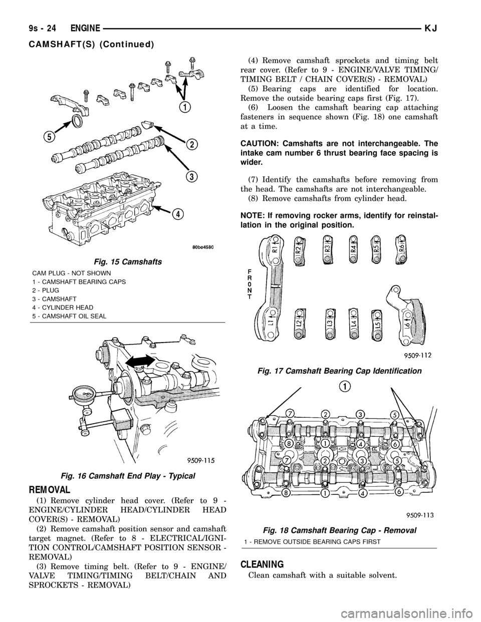
(5) Bearing caps are identified for location.
Remove the outside bearing caps first (Fig. 17).
(6) Loosen the camshaft bearing cap attaching
fasteners in sequence shown (Fig. 18) one camshaft
at a time.
CAUTION: Camshafts are not interchangeable. The
intake cam number 6 thrust bearing face spacing is
wider.
(7) Identify the camshafts before removing from
the head. The camshafts are not interchangeable.
(8) Remove camshafts from cylinder head.
NOTE: If removing rocker arms, identify for reinstal-
lation in the original position.
CLEANING
Clean camshaft with a suitable solvent.
Fig. 15 Camshafts
CAM PLUG - NOT SHOWN
1 - CAMSHAFT BEARING CAPS
2 - PLUG
3 - CAMSHAFT
4 - CYLINDER HEAD
5 - CAMSHAFT OIL SEAL
Fig. 16 Camshaft End Play - Typical
Fig. 17 Camshaft Bearing Cap Identification
Fig. 18 Camshaft Bearing Cap - Removal
1 - REMOVE OUTSIDE BEARING CAPS FIRST
9s - 24 ENGINEKJ
CAMSHAFT(S) (Continued)
Page 1332 of 1803
(6) Before installing the bolts the threads should
be oiled with clean engine oil, wipe off any excess oil.
(7) Install main bearing bedplate to engine block
bolts 11, 17, and 20 finger tight. Tighten these bolts
down together until the bedplate contacts the cylin-
der block.
(8) To ensure correct thrust bearing alignment,
perform the following steps:
²Step 1: Rotate crankshaft until number 4 piston
is at TDC.
²Step 2: Move crankshaft rearward to limits of
travel.
²Step 3: Then, move crankshaft forward to limits
of travel.
²Step 4: Wedge an appropriate tool between the
rear of the cylinder block(NOT BED PLATE)and
the rear crankshaft counterweight. This will hold the
crankshaft in it's furthest forward position.
²Step 5: Install and tighten bolts (1±10) in
sequence shown in (Fig. 45) to 41 N´m (30 ft. lbs.).
²Step 6: Remove wedge tool used to hold crank-
shaft.
(9) Tighten bolts (1±10) again to 41 N´m (30 ft.
lbs.) +1/4 turn in sequence shown in (Fig. 45).
(10) Install main bearing bedplate to engine block
bolts (11±20), and torque each bolt to 28 N´m (20 ft.
lbs.) in sequence shown in (Fig. 45).
(11) After the main bearing bedplate is installed,
check the crankshaft turning torque. The turning
torque should not exceed 5.6 N´m (50 in. lbs.).
(12) Install balance shafts and housing assembly.
(Refer to 9 - ENGINE/VALVE TIMING/BALANCE
SHAFT - INSTALLATION)
(13) Install the oil pump and pickup tube. (Refer
to 9 - ENGINE/LUBRICATION/OIL PUMP -
INSTALLATION)
(14) Install the timing belt rear cover. (Refer to 9 -
ENGINE/VALVE TIMING/TIMING BELT / CHAIN
COVER(S) - INSTALLATION)
(15) Install the timing belt. (Refer to 9 - ENGINE/
VALVE TIMING/TIMING BELT/CHAIN AND
SPROCKETS - INSTALLATION)
(16) Install the timing belt front covers. (Refer to 9
- ENGINE/VALVE TIMING/TIMING BELT / CHAIN
COVER(S) - INSTALLATION)
(17) Install engine support bracket.
(18) Install the oil pan. (Refer to 9 - ENGINE/LU-
BRICATION/OIL PAN - INSTALLATION)
(19) Install the oil filter.
(20) Install crankshaft rear oil seal. (Refer to 9 -
ENGINE/ENGINE BLOCK/CRANKSHAFT OIL
SEAL - REAR - INSTALLATION)
(21) Install flex plate. Apply MopartLock & Seal
Adhesive to bolt threads and tighten to 95 N´m (70
ft. lbs.).(22) Install the engine assembly. (Refer to 9 -
ENGINE - INSTALLATION)
CRANKSHAFT MAIN
BEARINGS
STANDARD PROCEDURE - MAIN BEARING -
FITTING
For crankshaft specifications (Refer to 9 - ENGINE
- SPECIFICATIONS).
CRANKSHAFT MAIN BEARINGS
The crankshaft is supported in five main bearings.
All upper and lower bearing shells in the crankcase
have oil grooves. Crankshaft end play is controlled by
a flanged bearing on the number three main bearing
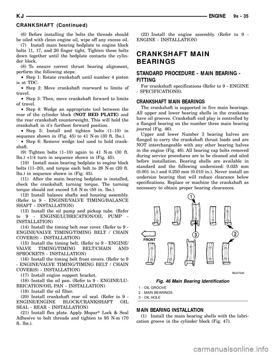
journal (Fig. 46).
Upper and lower Number 3 bearing halves are
flanged to carry the crankshaft thrust loads and are
NOT interchangeable with any other bearing halves
in the engine (Fig. 46). All bearing cap bolts removed
during service procedures are to be cleaned and oiled
before installation. Bearing shells are available in
standard and the following undersized: 0.025 mm
(0.001 in.) and 0.250 mm (0.010 in.). Never install an
undersize bearing that will reduce clearance below
specifications. Replace or machine the crankshaft as
necessary to obtain proper bearing clearances.
MAIN BEARING INSTALLATION
(1) Install the main bearing shells with the lubri-
cation groove in the cylinder block (Fig. 47).
Fig. 46 Main Bearing Identification
1 - OIL GROOVE
2 - MAIN BEARINGS
3 - OIL HOLE
KJENGINE9s-35
CRANKSHAFT (Continued)
Page 1338 of 1803
INSTALLATION
(1) Before installing pistons and connecting rod
assemblies into the bore, be sure that compression
ring gaps are staggered so that neither is in line with
oil ring rail gap.
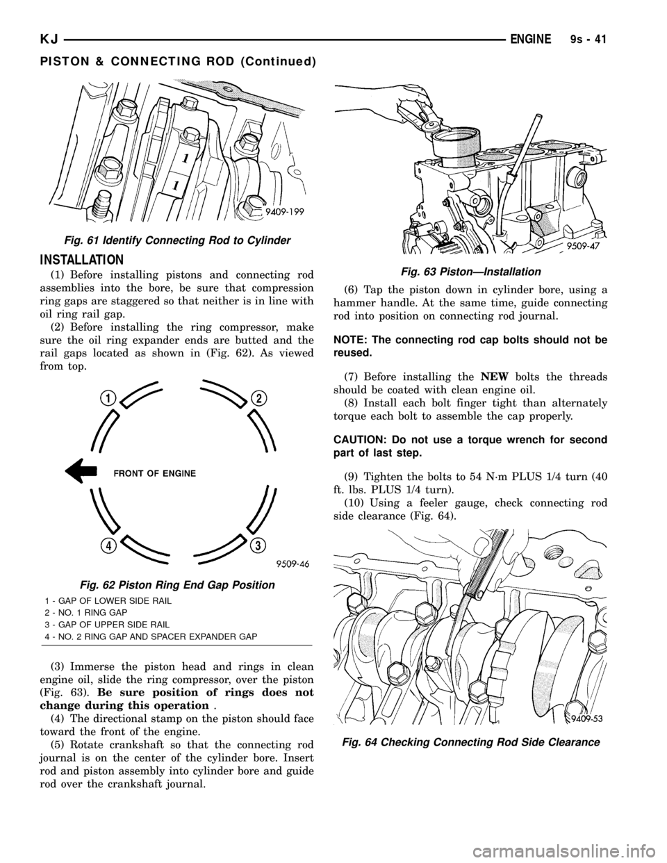
(2) Before installing the ring compressor, make
sure the oil ring expander ends are butted and the
rail gaps located as shown in (Fig. 62). As viewed
from top.
(3) Immerse the piston head and rings in clean
engine oil, slide the ring compressor, over the piston
(Fig. 63).Be sure position of rings does not
change during this operation.
(4) The directional stamp on the piston should face
toward the front of the engine.
(5) Rotate crankshaft so that the connecting rod
journal is on the center of the cylinder bore. Insert
rod and piston assembly into cylinder bore and guide
rod over the crankshaft journal.(6) Tap the piston down in cylinder bore, using a
hammer handle. At the same time, guide connecting
rod into position on connecting rod journal.
NOTE: The connecting rod cap bolts should not be
reused.
(7) Before installing theNEWbolts the threads
should be coated with clean engine oil.
(8) Install each bolt finger tight than alternately
torque each bolt to assemble the cap properly.
CAUTION: Do not use a torque wrench for second
part of last step.
(9) Tighten the bolts to 54 N´m PLUS 1/4 turn (40
ft. lbs. PLUS 1/4 turn).
(10) Using a feeler gauge, check connecting rod
side clearance (Fig. 64).
Fig. 61 Identify Connecting Rod to Cylinder
Fig. 62 Piston Ring End Gap Position
1 - GAP OF LOWER SIDE RAIL
2 - NO. 1 RING GAP
3 - GAP OF UPPER SIDE RAIL
4 - NO. 2 RING GAP AND SPACER EXPANDER GAP
Fig. 63 PistonÐInstallation
Fig. 64 Checking Connecting Rod Side Clearance
KJENGINE9s-41
PISTON & CONNECTING ROD (Continued)
Page 1344 of 1803
(6) Install oil pressure switch and connector. (Refer
to 9 - ENGINE/LUBRICATION/OIL PRESSURE
SENSOR/SWITCH - INSTALLATION)
OIL
STANDARD PROCEDURE
ENGINE OIL LEVEL CHECK
The best time to check engine oil level is after it
has sat overnight, or if the engine has been running,
allow the engine to be shut off for at least 5 minutes
before checking oil level.
Checking the oil while the vehicle is on level
ground will improve the accuracy of the oil level
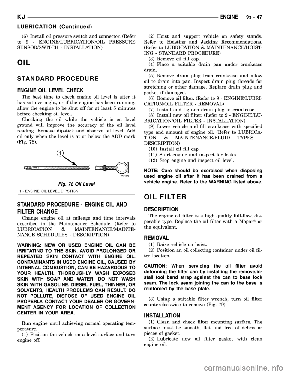
reading. Remove dipstick and observe oil level. Add
oil only when the level is at or below the ADD mark
(Fig. 78).
STANDARD PROCEDURE - ENGINE OIL AND
FILTER CHANGE
Change engine oil at mileage and time intervals
described in the Maintenance Schedule. (Refer to
LUBRICATION & MAINTENANCE/MAINTE-
NANCE SCHEDULES - DESCRIPTION)
WARNING: NEW OR USED ENGINE OIL CAN BE
IRRITATING TO THE SKIN. AVOID PROLONGED OR
REPEATED SKIN CONTACT WITH ENGINE OIL.
CONTAMINANTS IN USED ENGINE OIL, CAUSED BY
INTERNAL COMBUSTION, CAN BE HAZARDOUS TO
YOUR HEALTH. THOROUGHLY WASH EXPOSED
SKIN WITH SOAP AND WATER. DO NOT WASH
SKIN WITH GASOLINE, DIESEL FUEL, THINNER, OR
SOLVENTS, HEALTH PROBLEMS CAN RESULT. DO
NOT POLLUTE, DISPOSE OF USED ENGINE OIL
PROPERLY. CONTACT YOUR DEALER OR GOVERN-
MENT AGENCY FOR LOCATION OF COLLECTION
CENTER IN YOUR AREA.
Run engine until achieving normal operating tem-
perature.
(1) Position the vehicle on a level surface and turn
engine off.(2) Hoist and support vehicle on safety stands.
Refer to Hoisting and Jacking Recommendations.
(Refer to LUBRICATION & MAINTENANCE/HOIST-
ING - STANDARD PROCEDURE)
(3) Remove oil fill cap.
(4) Place a suitable drain pan under crankcase
drain.
(5) Remove drain plug from crankcase and allow
oil to drain into pan. Inspect drain plug threads for
stretching or other damage. Replace drain plug and
gasket if damaged.
(6) Remove oil filter. (Refer to 9 - ENGINE/LUBRI-
CATION/OIL FILTER - REMOVAL)
(7) Install and tighten drain plug in crankcase.
(8) Install new oil filter. (Refer to 9 - ENGINE/LU-
BRICATION/OIL FILTER - INSTALLATION)
(9) Lower vehicle and fill crankcase with specified
type and amount of engine oil. (Refer to LUBRICA-
TION & MAINTENANCE/FLUID TYPES -
DESCRIPTION)
(10) Install oil fill cap.
(11) Start engine and inspect for leaks.
(12) Stop engine and inspect oil level.
NOTE: Care should be exercised when disposing
used engine oil after it has been drained from a
vehicle engine. Refer to the WARNING listed above.
OIL FILTER
DESCRIPTION
The engine oil filter is a high quality full-flow, dis-
posable type. Replace the oil filter with a Mopartor
the equivalent.
REMOVAL
(1) Raise vehicle on hoist.
(2) Position an oil collecting container under oil fil-
ter location.
CAUTION: When servicing the oil filter avoid
deforming the filter can by installing the remove/in-
stall tool band strap against the can to base lock
seam. The lock seam joining the can to the base is
reinforced by the base plate.
(3) Using a suitable filter wrench, turn oil filter
counterclockwise to remove (Fig. 79).
INSTALLATION
(1) Clean and check filter mounting surface. The
surface must be smooth, flat and free of debris or
pieces of gasket.
(2) Lubricate new oil filter gasket with clean
engine oil.
Fig. 78 Oil Level
1 - ENGINE OIL LEVEL DIPSTICK
KJENGINE9s-47
LUBRICATION (Continued)