2002 JEEP LIBERTY Change JB
[x] Cancel search: Change JBPage 1057 of 1803
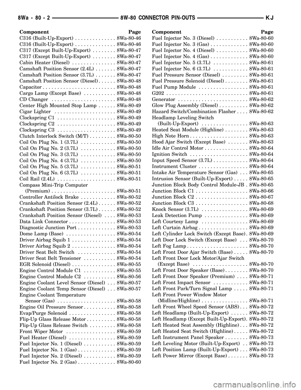
Component Page
C316 (Built-Up-Export).............. 8Wa-80-46
C316 (Built-Up-Export).............. 8Wa-80-46
C317 (Except Built-Up-Export)........ 8Wa-80-47
C317 (Except Built-Up-Export)........ 8Wa-80-47
Cabin Heater (Diesel)............... 8Wa-80-47
Camshaft Position Sensor (2.4L)....... 8Wa-80-47
Camshaft Position Sensor (3.7L)....... 8Wa-80-47
Camshaft Position Sensor (Diesel)...... 8Wa-80-48
Capacitor......................... 8Wa-80-48
Cargo Lamp (Except Base)........... 8Wa-80-48
CD Changer...................... 8Wa-80-48
Center High Mounted Stop Lamp...... 8Wa-80-49
Cigar Lighter..................... 8Wa-80-49
Clockspring C1.................... 8Wa-80-49
Clockspring C2.................... 8Wa-80-49
Clockspring C3.................... 8Wa-80-49
Clutch Interlock Switch (M/T)......... 8Wa-80-50
Coil On Plug No. 1 (3.7L)............ 8Wa-80-50
Coil On Plug No. 2 (3.7L)............ 8Wa-80-50
Coil On Plug No. 3 (3.7L)............ 8Wa-80-50
Coil On Plug No. 4 (3.7L)............ 8Wa-80-50
Coil On Plug No. 5 (3.7L)............ 8Wa-80-51
Coil On Plug No. 6 (3.7L)............ 8Wa-80-51
Coil Rail (2.4L).................... 8Wa-80-51
Compass Mini-Trip Computer
(Premium)...................... 8Wa-80-51
Controller Antilock Brake............ 8Wa-80-52
Crankshaft Position Sensor (2.4L)...... 8Wa-80-52
Crankshaft Position Sensor (3.7L)...... 8Wa-80-52
Crankshaft Position Sensor (Diesel).... 8Wa-80-53
Data Link Connector................ 8Wa-80-53
Diagnostic Junction Port............. 8Wa-80-53
Dome Lamp (Base)................. 8Wa-80-54
Driver Airbag Squib 1............... 8Wa-80-54
Driver Airbag Squib 2............... 8Wa-80-54
Driver Seat Belt Switch............. 8Wa-80-54
Driver Seat Belt Tensioner........... 8Wa-80-54
EGR Solenoid (Diesel)............... 8Wa-80-55
Engine Control Module C1........... 8Wa-80-55
Engine Control Module C2........... 8Wa-80-56
Engine Coolant Level Sensor (Diesel) . . . 8Wa-80-57
Engine Coolant Temp Sensor (Diesel) . . . 8Wa-80-57
Engine Coolant Temperature
Sensor (Gas).................... 8Wa-80-58
Engine Oil Pressure Sensor........... 8Wa-80-58
Evap/Purge Solenoid................ 8Wa-80-58
Flip-Up Glass Release Motor.......... 8Wa-80-58
Flip-Up Glass Release Switch......... 8Wa-80-58
Front Wiper Motor................. 8Wa-80-59
Fuel Heater (Diesel)................ 8Wa-80-59
Fuel Injector No. 1 (Diesel)........... 8Wa-80-59
Fuel Injector No. 1 (Gas)............. 8Wa-80-59
Fuel Injector No. 2 (Diesel)........... 8Wa-80-59
Fuel Injector No. 2 (Gas)............. 8Wa-80-60Component Page
Fuel Injector No. 3 (Diesel)........... 8Wa-80-60
Fuel Injector No. 3 (Gas)............. 8Wa-80-60
Fuel Injector No. 4 (Diesel)........... 8Wa-80-60
Fuel Injector No. 4 (Gas)............. 8Wa-80-60
Fuel Injector No. 5 (3.7L)............ 8Wa-80-61
Fuel Injector No. 6 (3.7L)............ 8Wa-80-61
Fuel Pressure Sensor (Diesel)......... 8Wa-80-61
Fuel Pressure Solenoid (Diesel)........ 8Wa-80-61
Fuel Pump Module................. 8Wa-80-61
G202............................ 8Wa-80-61
Generator........................ 8Wa-80-62
Glow Plug Assembly (Diesel).......... 8Wa-80-62
Hazard Switch/Combination Flasher.... 8Wa-80-62
Headlamp Leveling Switch
(Built-Up-Export)................ 8Wa-80-63
Heated Seat Module (Highline)........ 8Wa-80-63
High Note Horn.................... 8Wa-80-63
Hood Ajar Switch (Except Base)....... 8Wa-80-63
Idle Air Control Motor............... 8Wa-80-64
Ignition Switch.................... 8Wa-80-64
Input Speed Sensor (3.7L)............ 8Wa-80-64
Instrument Cluster................. 8Wa-80-64
Intake Air Temperature Sensor (Gas) . . . 8Wa-80-65
Intrusion Sensor (Built-Up-Export)..... 8Wa-80-65
Junction Block Body Control Module-JB . 8Wa-80-65
Junction Block C1.................. 8Wa-80-66
Junction Block C2.................. 8Wa-80-67
Junction Block C3.................. 8Wa-80-68
Knock Sensor (3.7L)................ 8Wa-80-69
Leak Detection Pump............... 8Wa-80-69
Left Courtesy Lamp................ 8Wa-80-69
Left Curtain Airbag................. 8Wa-80-69
Left Cylinder Lock Switch (Except Base) . 8Wa-80-69
Left Door Lock Switch (Except Base) . . . 8Wa-80-70
Left Fog Lamp..................... 8Wa-80-70
Left Front Door Ajar Switch (Base)..... 8Wa-80-70
Left Front Door Lock Motor/Ajar Switch
(Except Base)................... 8Wa-80-70
Left Front Door Speaker (Base)........ 8Wa-80-70
Left Front Door Speaker (Premium).... 8Wa-80-71
Left Front Impact Sensor............ 8Wa-80-71
Left Front Park/Turn Signal Lamp..... 8Wa-80-71
Left Front Power Window Motor
(Midline/Highline)................ 8Wa-80-71
Left Front Wheel Speed Sensor (ABS) . . . 8Wa-80-72
Left Headlamp (Built-Up-Export)...... 8Wa-80-72
Left Headlamp (Except Built-Up-Export) . 8Wa-80-72
Left Heated Seat Assembly (Highline) . . . 8Wa-80-72
Left Heated Seat Switch (Highline)..... 8Wa-80-72
Left Instrument Panel Speaker........ 8Wa-80-73
Left Leveling Motor (Built-Up-Export) . . 8Wa-80-73
Left Position Lamp (Built-Up-Export) . . . 8Wa-80-73
Left Power Mirror (Except Base)....... 8Wa-80-73
8Wa - 80 - 2 8W-80 CONNECTOR PIN-OUTSKJ
Page 1103 of 1803
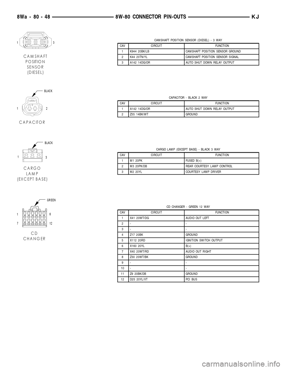
CAMSHAFT POSITION SENSOR (DIESEL)-3WAY
CAV CIRCUIT FUNCTION
1 K944 20BK/LB CAMSHAFT POSITION SENSOR GROUND
2 K44 20TN/YL CAMSHAFT POSITION SENSOR SIGNAL
3 A142 14DG/OR AUTO SHUT DOWN RELAY OUTPUT
CAPACITOR - BLACK 2 WAY
CAV CIRCUIT FUNCTION
1 A142 14DG/OR AUTO SHUT DOWN RELAY OUTPUT
2 Z55 14BK/WT GROUND
CARGO LAMP (EXCEPT BASE) - BLACK 3 WAY
CAV CIRCUIT FUNCTION
1 M1 20PK FUSED B(+)
2 M3 20PK/DB REAR COURTESY LAMP CONTROL
3 M2 20YL COURTESY LAMP DRIVER
CD CHANGER - GREEN 12 WAY
CAV CIRCUIT FUNCTION
1 X41 20WT/DG AUDIO OUT LEFT
2- -
3- -
4 Z17 20BK GROUND
5 X112 20RD IGNITION SWITCH OUTPUT
6 X160 20YL B(+)
7 X40 20WT/RD AUDIO OUT RIGHT
8 Z30 20WT/BK GROUND
9- -
10 - -
11 Z9 20BK/DB GROUND
12 D25 20YL/VT PCI BUS
8Wa - 80 - 48 8W-80 CONNECTOR PIN-OUTSKJ
Page 1158 of 1803
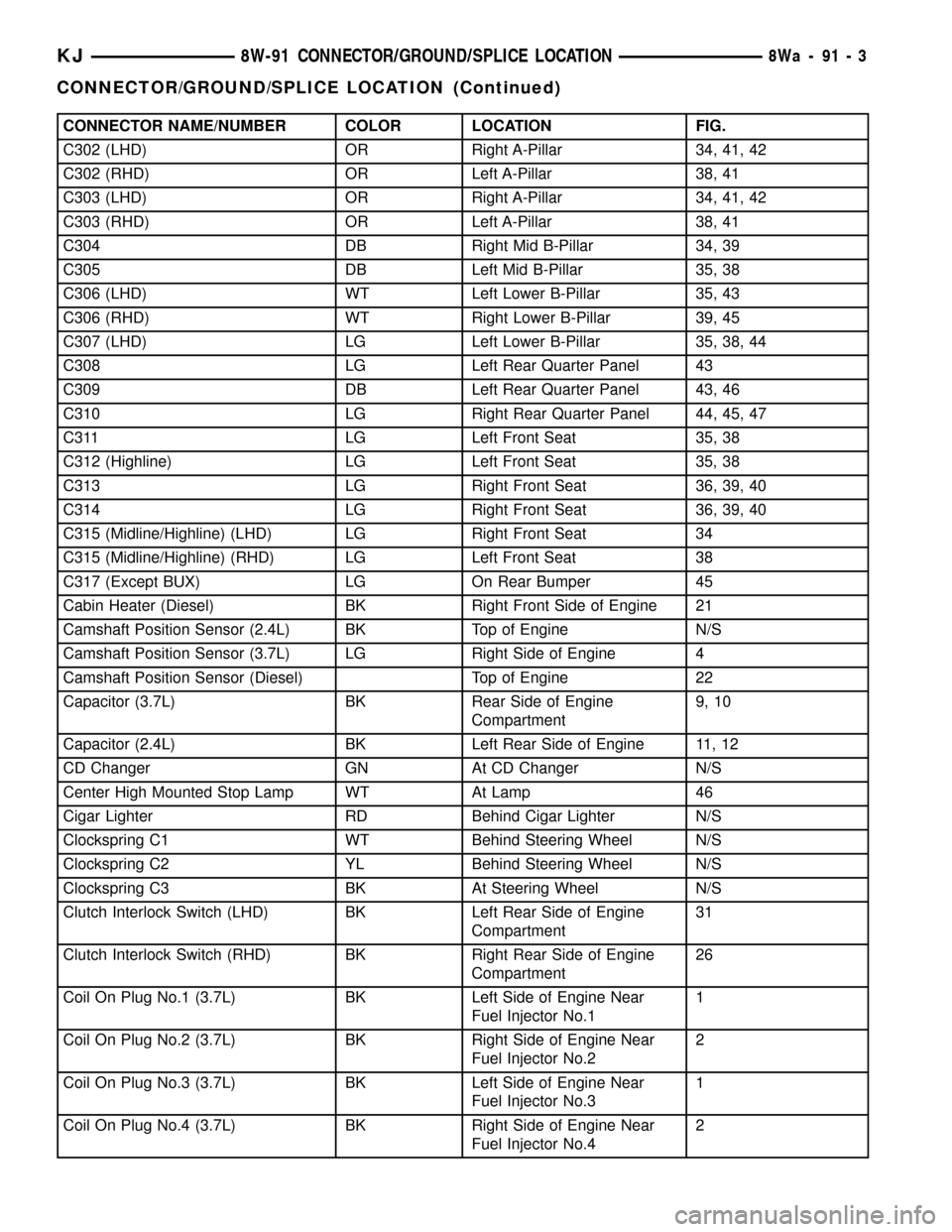
CONNECTOR NAME/NUMBER COLOR LOCATION FIG.
C302 (LHD) OR Right A-Pillar 34, 41, 42
C302 (RHD) OR Left A-Pillar 38, 41
C303 (LHD) OR Right A-Pillar 34, 41, 42
C303 (RHD) OR Left A-Pillar 38, 41
C304 DB Right Mid B-Pillar 34, 39
C305 DB Left Mid B-Pillar 35, 38
C306 (LHD) WT Left Lower B-Pillar 35, 43
C306 (RHD) WT Right Lower B-Pillar 39, 45
C307 (LHD) LG Left Lower B-Pillar 35, 38, 44
C308 LG Left Rear Quarter Panel 43
C309 DB Left Rear Quarter Panel 43, 46
C310 LG Right Rear Quarter Panel 44, 45, 47
C311 LG Left Front Seat 35, 38
C312 (Highline) LG Left Front Seat 35, 38
C313 LG Right Front Seat 36, 39, 40
C314 LG Right Front Seat 36, 39, 40
C315 (Midline/Highline) (LHD) LG Right Front Seat 34
C315 (Midline/Highline) (RHD) LG Left Front Seat 38
C317 (Except BUX) LG On Rear Bumper 45
Cabin Heater (Diesel) BK Right Front Side of Engine 21
Camshaft Position Sensor (2.4L) BK Top of Engine N/S
Camshaft Position Sensor (3.7L) LG Right Side of Engine 4
Camshaft Position Sensor (Diesel) Top of Engine 22
Capacitor (3.7L) BK Rear Side of Engine
Compartment9, 10
Capacitor (2.4L) BK Left Rear Side of Engine 11, 12
CD Changer GN At CD Changer N/S
Center High Mounted Stop Lamp WT At Lamp 46
Cigar Lighter RD Behind Cigar Lighter N/S
Clockspring C1 WT Behind Steering Wheel N/S
Clockspring C2 YL Behind Steering Wheel N/S
Clockspring C3 BK At Steering Wheel N/S
Clutch Interlock Switch (LHD) BK Left Rear Side of Engine
Compartment31
Clutch Interlock Switch (RHD) BK Right Rear Side of Engine
Compartment26
Coil On Plug No.1 (3.7L) BK Left Side of Engine Near
Fuel Injector No.11
Coil On Plug No.2 (3.7L) BK Right Side of Engine Near
Fuel Injector No.22
Coil On Plug No.3 (3.7L) BK Left Side of Engine Near
Fuel Injector No.31
Coil On Plug No.4 (3.7L) BK Right Side of Engine Near
Fuel Injector No.42
KJ8W-91 CONNECTOR/GROUND/SPLICE LOCATION8Wa-91-3
CONNECTOR/GROUND/SPLICE LOCATION (Continued)
Page 1221 of 1803
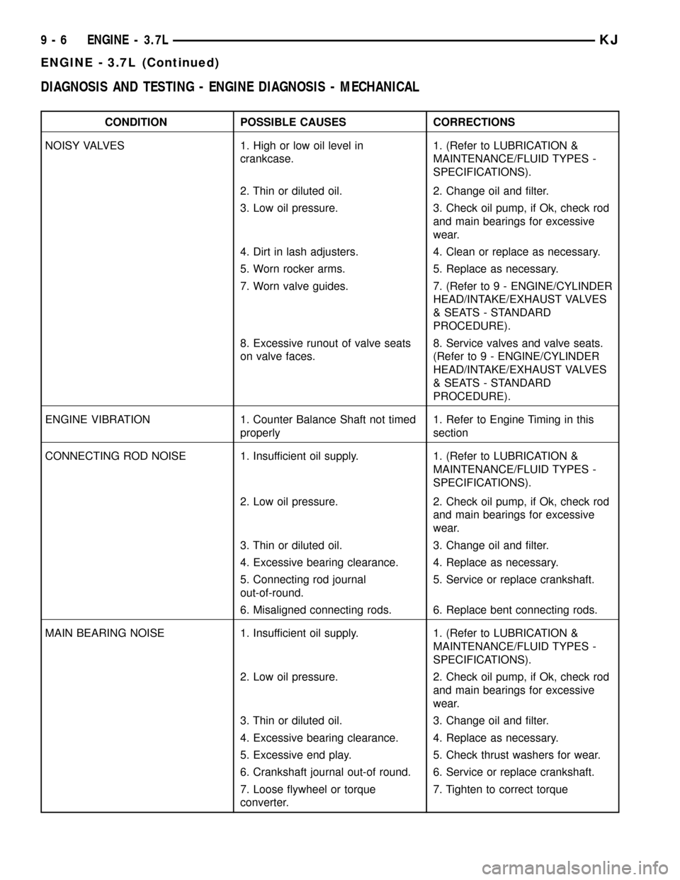
DIAGNOSIS AND TESTING - ENGINE DIAGNOSIS - MECHANICAL
CONDITION POSSIBLE CAUSES CORRECTIONS
NOISY VALVES 1. High or low oil level in
crankcase.1. (Refer to LUBRICATION &
MAINTENANCE/FLUID TYPES -
SPECIFICATIONS).
2. Thin or diluted oil. 2. Change oil and filter.
3. Low oil pressure. 3. Check oil pump, if Ok, check rod
and main bearings for excessive
wear.
4. Dirt in lash adjusters. 4. Clean or replace as necessary.
5. Worn rocker arms. 5. Replace as necessary.
7. Worn valve guides. 7. (Refer to 9 - ENGINE/CYLINDER
HEAD/INTAKE/EXHAUST VALVES
& SEATS - STANDARD
PROCEDURE).
8. Excessive runout of valve seats
on valve faces.8. Service valves and valve seats.
(Refer to 9 - ENGINE/CYLINDER
HEAD/INTAKE/EXHAUST VALVES
& SEATS - STANDARD
PROCEDURE).
ENGINE VIBRATION 1. Counter Balance Shaft not timed
properly1. Refer to Engine Timing in this
section
CONNECTING ROD NOISE 1. Insufficient oil supply. 1. (Refer to LUBRICATION &
MAINTENANCE/FLUID TYPES -
SPECIFICATIONS).
2. Low oil pressure. 2. Check oil pump, if Ok, check rod
and main bearings for excessive
wear.
3. Thin or diluted oil. 3. Change oil and filter.
4. Excessive bearing clearance. 4. Replace as necessary.
5. Connecting rod journal
out-of-round.5. Service or replace crankshaft.
6. Misaligned connecting rods. 6. Replace bent connecting rods.
MAIN BEARING NOISE 1. Insufficient oil supply. 1. (Refer to LUBRICATION &
MAINTENANCE/FLUID TYPES -
SPECIFICATIONS).
2. Low oil pressure. 2. Check oil pump, if Ok, check rod
and main bearings for excessive
wear.
3. Thin or diluted oil. 3. Change oil and filter.
4. Excessive bearing clearance. 4. Replace as necessary.
5. Excessive end play. 5. Check thrust washers for wear.
6. Crankshaft journal out-of round. 6. Service or replace crankshaft.
7. Loose flywheel or torque
converter.7. Tighten to correct torque
9 - 6 ENGINE - 3.7LKJ
ENGINE - 3.7L (Continued)
Page 1222 of 1803
DIAGNOSIS AND TESTING - ENGINE DIAGNOSIS - LUBRICATION
CONDITION POSSIBLE CAUSES CORRECTION
OIL LEAKS 1. Gaskets and O-Rings. 1.
(a) Misaligned or damaged. (a) Replace as necessary.
(b) Loose fasteners, broken or
porous metal parts.(b) Tighten fasteners, Repair or
replace metal parts.
2. Crankshaft rear seal 2. Replace as necessary (Refer to 9
- ENGINE/ENGINE BLOCK/
CRANKSHAFT OIL SEAL - REAR -
REMOVAL).
3. Crankshaft seal flange.
Scratched, nicked or grooved.3. Polish or replace crankshaft.
4. Oil pan flange cracked. 4. Replace oil pan (Refer to 9 -
ENGINE/LUBRICATION/OIL PAN -
REMOVAL).
5. Timing chain cover seal
damaged.5. Re-seal timing cover.
6. Scratched or damaged vibration
damper hub.6. Polish or replace damper.
OIL PRESSURE DROP 1. Low oil level. 1. Check and correct oil level.
2. Faulty oil pressure sending unit. 2. Replace sending unit (Refer to 9
- ENGINE/LUBRICATION/OIL
PRESSURE SENSOR/SWITCH -
REMOVAL).
3. Low oil pressure. 3. Check oil pump and bearing
clearance.
4. Clogged oil filter. 4. Replace oil filter (Refer to 9 -
ENGINE/LUBRICATION/OIL FILTER
- REMOVAL).
5. Worn oil pump. 5. Replace oil pump (Refer to 9 -
ENGINE/LUBRICATION/OIL PUMP
- REMOVAL).
6. Thin or diluted oil. 6. Change oil and filter.
7. Excessive bearing clearance. 7. Replace as necessary.
8. Oil pump relief valve stuck. 8. Replace oil pump (Refer to 9 -
ENGINE/LUBRICATION/OIL PUMP
- REMOVAL).
9. Oil pump suction tube loose,
damaged or clogged.9. Replace as necessary.
KJENGINE - 3.7L 9 - 7
ENGINE - 3.7L (Continued)
Page 1266 of 1803
assemblies from the engine, rotate crankshaft so the
each connecting rod is centered in cylinder bore.
CAUTION: DO NOT use a number stamp or a punch
to mark connecting rods or caps, as damage to
connecting rods could occur
NOTE: Connecting rods and bearing caps are not
interchangeable and should be marked before
removing to ensure correct reassembly.
(4) Mark connecting rod and bearing cap positions
using a permanent ink marker or scribe tool.
CAUTION: Care must be taken not to damage the
fractured rod and cap joint face surfaces, as engine
damage may occur.
(5) Remove connecting rod cap. Install Special Tool
8507 Connecting Rod Guides into the connecting rod
being removed. Remove piston from cylinder bore.
Repeat this procedure for each piston being removed.
CAUTION: Care must be taken not to nick crank-
shaft journals, as engine damage may occur
(6) Immediately after piston and connecting rod
removal, install bearing cap on the mating connect-
ing rod to prevent damage to the fractured cap and
rod surfaces.
CLEANING
CAUTION: DO NOT use a wire wheel or other abra-
sive cleaning devise to clean the pistons or con-
necting rods. The pistons have a Moly coating, this
coating must not be damaged.
(1) Using a suitable cleaning solvent clean the pis-
tons in warm water and towel dry.
(2) Use a wood or plastic scraper to clean the ring
land grooves.
CAUTION: DO NOT remove the piston pin from the
piston and connecting rod assembly.
INSPECTION
Check the connecting rod journal for excessive
wear, taper and scoring (Refer to 9 - ENGINE/EN-
GINE BLOCK/CONNECTING ROD BEARINGS -
STANDARD PROCEDURE).
Check the connecting rod for signs of twist or bend-
ing.
Check the piston for taper and elliptical shape
before it is fitted into the cylinder bore (Refer to 9 -
ENGINE/ENGINE BLOCK/PISTON & CONNECT-
ING ROD - STANDARD PROCEDURE).
Check the piston for scoring, or scraping marks in
the piston skirts. Check the ring lands for cracks
and/or deterioration.
INSTALLATION
(1) Before installing piston and connecting rod
assemblies into the bore, install the piston rings.
(2) Immerse the piston head and rings in clean
engine oil. Position a ring compressor over the piston
and rings. Tighten ring compressor.Ensure posi-
tion of rings do not change during this opera-
tion.
(3) Position bearing onto connecting rod. Ensure
that tabs in bearing shell aligns with slots in con-
necting rod. Verify that parting line of bearing is
aligned with parting line of connecting rod.
(4) Lubricate bearing surface with clean engine oil.
(5) Install Special Tool 8507 Connecting Rod
Guides into connecting rod bolt threads (Fig. 55).
(6) The pistons are marked on the piston pin bore
surface with an raised ªFº indicating installation
position. This mark must be pointing toward the
front of engine on both cylinder banks. The connect-
ing rod oil slinger slot faces the front of the engine
(Fig. 56).
(7) Wipe cylinder bore clean and lubricate with
engine oil.
(8) Rotate crankshaft until connecting rod journal
is on the center of cylinder bore. Insert rod and pis-
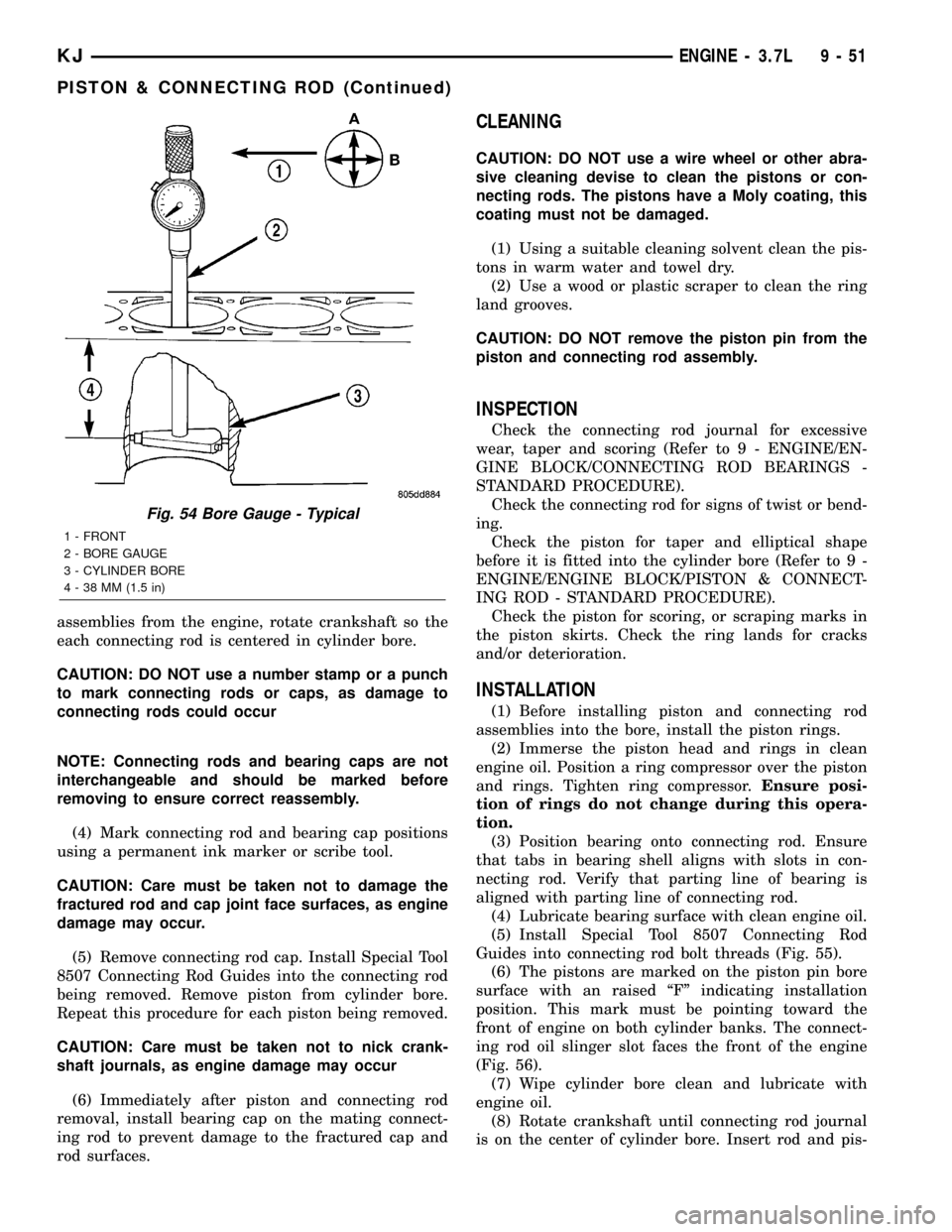
Fig. 54 Bore Gauge - Typical
1 - FRONT
2 - BORE GAUGE
3 - CYLINDER BORE
4 - 38 MM (1.5 in)
KJENGINE - 3.7L 9 - 51
PISTON & CONNECTING ROD (Continued)
Page 1277 of 1803
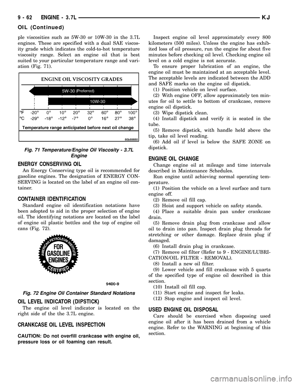
ple viscosities such as 5W-30 or 10W-30 in the 3.7L
engines. These are specified with a dual SAE viscos-
ity grade which indicates the cold-to-hot temperature
viscosity range. Select an engine oil that is best
suited to your particular temperature range and vari-
ation (Fig. 71).
ENERGY CONSERVING OIL
An Energy Conserving type oil is recommended for
gasoline engines. The designation of ENERGY CON-
SERVING is located on the label of an engine oil con-
tainer.
CONTAINER IDENTIFICATION
Standard engine oil identification notations have
been adopted to aid in the proper selection of engine
oil. The identifying notations are located on the label
of engine oil plastic bottles and the top of engine oil
cans (Fig. 72).
OIL LEVEL INDICATOR (DIPSTICK)
The engine oil level indicator is located on the
right side of the the 3.7L engine.
CRANKCASE OIL LEVEL INSPECTION
CAUTION: Do not overfill crankcase with engine oil,
pressure loss or oil foaming can result.Inspect engine oil level approximately every 800
kilometers (500 miles). Unless the engine has exhib-
ited loss of oil pressure, run the engine for about five
minutes before checking oil level. Checking engine oil
level on a cold engine is not accurate.
To ensure proper lubrication of an engine, the
engine oil must be maintained at an acceptable level.
The acceptable levels are indicated between the ADD
and SAFE marks on the engine oil dipstick.
(1) Position vehicle on level surface.
(2) With engine OFF, allow approximately ten min-
utes for oil to settle to bottom of crankcase, remove
engine oil dipstick.
(3) Wipe dipstick clean.
(4) Install dipstick and verify it is seated in the
tube.
(5) Remove dipstick, with handle held above the
tip, take oil level reading.
(6) Add oil if level is below the SAFE ZONE on
dipstick.
ENGINE OIL CHANGE
Change engine oil at mileage and time intervals
described in Maintenance Schedules.
Run engine until achieving normal operating tem-
perature.
(1) Position the vehicle on a level surface and turn
engine off.
(2) Remove oil fill cap.
(3) Hoist and support vehicle on safety stands.
(4) Place a suitable drain pan under crankcase
drain.
(5) Remove drain plug from crankcase and allow
oil to drain into pan. Inspect drain plug threads for
stretching or other damage. Replace drain plug if
damaged.
(6) Install drain plug in crankcase.
(7) Remove oil filter (Refer to 9 - ENGINE/LUBRI-
CATION/OIL FILTER - REMOVAL).
(8) Install a new oil filter.
(9) Lower vehicle and fill crankcase with 5 quarts
of the specified type of engine oil described in this
section.
(10) Install oil fill cap.
(11) Start engine and inspect for leaks.
(12) Stop engine and inspect oil level.
USED ENGINE OIL DISPOSAL
Care should be exercised when disposing used
engine oil after it has been drained from a vehicle
engine. Refer to the WARNING at beginning of this
section.
Fig. 71 Temperature/Engine Oil Viscosity - 3.7L
Engine
Fig. 72 Engine Oil Container Standard Notations
9 - 62 ENGINE - 3.7LKJ
OIL (Continued)
Page 1283 of 1803
INTAKE MANIFOLD
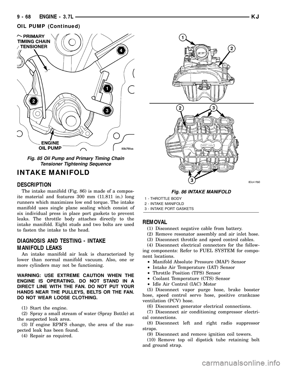
DESCRIPTION
The intake manifold (Fig. 86) is made of a compos-
ite material and features 300 mm (11.811 in.) long
runners which maximizes low end torque. The intake
manifold uses single plane sealing which consist of
six individual press in place port gaskets to prevent
leaks. The throttle body attaches directly to the
intake manifold. Eight studs and two bolts are used
to fasten the intake to the head.
DIAGNOSIS AND TESTING - INTAKE
MANIFOLD LEAKS
An intake manifold air leak is characterized by
lower than normal manifold vacuum. Also, one or
more cylinders may not be functioning.
WARNING: USE EXTREME CAUTION WHEN THE
ENGINE IS OPERATING. DO NOT STAND IN A
DIRECT LINE WITH THE FAN. DO NOT PUT YOUR
HANDS NEAR THE PULLEYS, BELTS OR THE FAN.
DO NOT WEAR LOOSE CLOTHING.
(1) Start the engine.
(2) Spray a small stream of water (Spray Bottle) at
the suspected leak area.
(3) If engine RPM'S change, the area of the sus-
pected leak has been found.
(4) Repair as required.
REMOVAL
(1) Disconnect negative cable from battery.
(2) Remove resonator assembly and air inlet hose.
(3) Disconnect throttle and speed control cables.
(4) Disconnect electrical connectors for the follow-
ing components: Refer to FUEL SYSTEM for compo-
nent locations.
²Manifold Absolute Pressure (MAP) Sensor
²Intake Air Temperature (IAT) Sensor
²Throttle Position (TPS) Sensor
²Coolant Temperature (CTS) Sensor
²Idle Air Control (IAC) Motor
(5) Disconnect vapor purge hose, brake booster
hose, speed control servo hose, positive crankcase
ventilation (PCV) hose.
(6) Disconnect generator electrical connections.
(7) Disconnect air conditioning compressor electri-
cal connections.
(8) Disconnect left and right radio suppressor
straps.
(9) Disconnect and remove ignition coil towers.
(10) Remove top oil dipstick tube retaining bolt
and ground strap.
Fig. 85 Oil Pump and Primary Timing Chain
Tensioner Tightening Sequence
Fig. 86 INTAKE MANIFOLD
1 - THROTTLE BODY
2 - INTAKE MANIFOLD
3 - INTAKE PORT GASKETS
9 - 68 ENGINE - 3.7LKJ
OIL PUMP (Continued)