Page 1963 of 2100

switch, door lock actuator for the front and rear door,
tailgate lock actuato")
SECURITY AND LOCKS8H±13
Power Door Lock System
General Description
The circuit consists of the door lock (& power window)
switch, door lock actuator for the front and rear door,
tailgate lock actuator and the door lock key switch.
The front door lock switch±LH is always provided with the
battery voltage.
The key or the inside lock button on both driver's and front
passenger's door can activate the lock mechanism of all
the doors (including the tailgate).
When the driver's door lock switch or the front
passenger's door lock switch is turned on, current flows
for about one second to the door lock actuator of each
door connected in parallel with the front door lock (&
power window) switch±LH to activate the actuator to lock
and unlock the doors.
Door Lock Key Switch
Removal and Installation
�Refer to the Front Door Lock Assembly removal and
installation steps in this section.
Front Door Lock Actuator
Removal and Installation
�Refer to the Front Door Lock Assembly removal and
installation steps in this section.
Rear Door Lock Actuator
Removal and Installation
�Refer to the Rear Door Lock Assembly removal and
installation steps in this section.
Tailgate Lock Actuator
Removal and Installation
�Refer to the Tailgate Lock Assembly removal and
installation steps in this section.
Page 1979 of 2100

EXTERIOR/INTERIOR TRIM8J±1
AXIOM
BODY AND ACCESSORIES
EXTERIOR / INTERIOR TRIM
CONTENTS
Service Precaution 8J±2. . . . . . . . . . . . . . . . . . . . . .
Consoles 8J±3. . . . . . . . . . . . . . . . . . . . . . . . . . . . . . .
Consoles and Associated Parts 8J±3. . . . . . . . .
Removal 8J±3. . . . . . . . . . . . . . . . . . . . . . . . . . . . .
Installation 8J±4. . . . . . . . . . . . . . . . . . . . . . . . . . . .
Front Door Trim Panel 8J±4. . . . . . . . . . . . . . . . . . .
Front Door Trim Panel and Associated
Parts 8J±4. . . . . . . . . . . . . . . . . . . . . . . . . . . . . . . .
Removal 8J±5. . . . . . . . . . . . . . . . . . . . . . . . . . . . .
Installation 8J±5. . . . . . . . . . . . . . . . . . . . . . . . . . . .
Rear Door Trim Panel 8J±6. . . . . . . . . . . . . . . . . . . .
Rear Door Trim Panel and Associated
Parts 8J±6. . . . . . . . . . . . . . . . . . . . . . . . . . . . . . . .
Removal 8J±7. . . . . . . . . . . . . . . . . . . . . . . . . . . . .
Installation 8J±7. . . . . . . . . . . . . . . . . . . . . . . . . . . .
Door Mirror Assembly 8J±8. . . . . . . . . . . . . . . . . . . .
Removal 8J±8. . . . . . . . . . . . . . . . . . . . . . . . . . . . .
Installation 8J±8. . . . . . . . . . . . . . . . . . . . . . . . . . . .
Interior Mirror Assembly 8J±8. . . . . . . . . . . . . . . . . .
Removal 8J±8. . . . . . . . . . . . . . . . . . . . . . . . . . . . .
Installation 8J±8. . . . . . . . . . . . . . . . . . . . . . . . . . . .
Interior Trim Panels 8J±9. . . . . . . . . . . . . . . . . . . . . .
Interior Trim Panels and Associated Parts 8J±9
Removal 8J±9. . . . . . . . . . . . . . . . . . . . . . . . . . . . .
Installation 8J±11. . . . . . . . . . . . . . . . . . . . . . . . . . . .
Headlining 8J±12. . . . . . . . . . . . . . . . . . . . . . . . . . . . . .
Parts Location 8J±12. . . . . . . . . . . . . . . . . . . . . . . .
Removal 8J±12. . . . . . . . . . . . . . . . . . . . . . . . . . . . .
Installation 8J±13. . . . . . . . . . . . . . . . . . . . . . . . . . . .
Overhead Console 8J±14. . . . . . . . . . . . . . . . . . . . . . Parts Location (W/O Sunroof) 8J±14. . . . . . . . . . .
Removal 8J±14. . . . . . . . . . . . . . . . . . . . . . . . . . . . .
Installation 8J±14. . . . . . . . . . . . . . . . . . . . . . . . . . . .
Parts Location (W/ Sunroof) 8J±15. . . . . . . . . . . . .
Removal 8J±15. . . . . . . . . . . . . . . . . . . . . . . . . . . . .
Installation 8J±15. . . . . . . . . . . . . . . . . . . . . . . . . . . .
Wheel Arch Cover 8J±16. . . . . . . . . . . . . . . . . . . . . . .
Wheel Arch Cover and Associated Parts 8J±16. .
Removal 8J±16. . . . . . . . . . . . . . . . . . . . . . . . . . . . .
Installation 8J±16. . . . . . . . . . . . . . . . . . . . . . . . . . . .
Locker Cover 8J±17. . . . . . . . . . . . . . . . . . . . . . . . . . .
Locker Cover and Associated Parts 8J±17. . . . . .
Removal 8J±17. . . . . . . . . . . . . . . . . . . . . . . . . . . . .
Installation 8J±17. . . . . . . . . . . . . . . . . . . . . . . . . . . .
Fuel Filler Door 8J±18. . . . . . . . . . . . . . . . . . . . . . . . .
Parts Location 8J±18. . . . . . . . . . . . . . . . . . . . . . . .
Removal 8J±18. . . . . . . . . . . . . . . . . . . . . . . . . . . . .
Installation 8J±18. . . . . . . . . . . . . . . . . . . . . . . . . . . .
Roof Moulding 8J±19. . . . . . . . . . . . . . . . . . . . . . . . . .
Parts Location 8J±19. . . . . . . . . . . . . . . . . . . . . . . .
Removal 8J±19. . . . . . . . . . . . . . . . . . . . . . . . . . . . .
Installation 8J±19. . . . . . . . . . . . . . . . . . . . . . . . . . . .
Power Door Mirror System 8J±20. . . . . . . . . . . . . . .
General Description 8J±20. . . . . . . . . . . . . . . . . . . . .
Door Mirror Switch 8J±20. . . . . . . . . . . . . . . . . . . . .
Power Window System 8J±21. . . . . . . . . . . . . . . . . .
General Description 8J±21. . . . . . . . . . . . . . . . . . . . .
Power Window Switch Driver Seat Side 8J±21. .
Power Window Motor 8J±22. . . . . . . . . . . . . . . . . .
Main Data and Specifications 8J±23. . . . . . . . . . . . .
Page 1982 of 2100
8J±4EXTERIOR/INTERIOR TRIM
7. Remove the CD changer.
�Remove the four fixing bolts and the connector.Installation
To install, follow the removal steps in the reverse order.
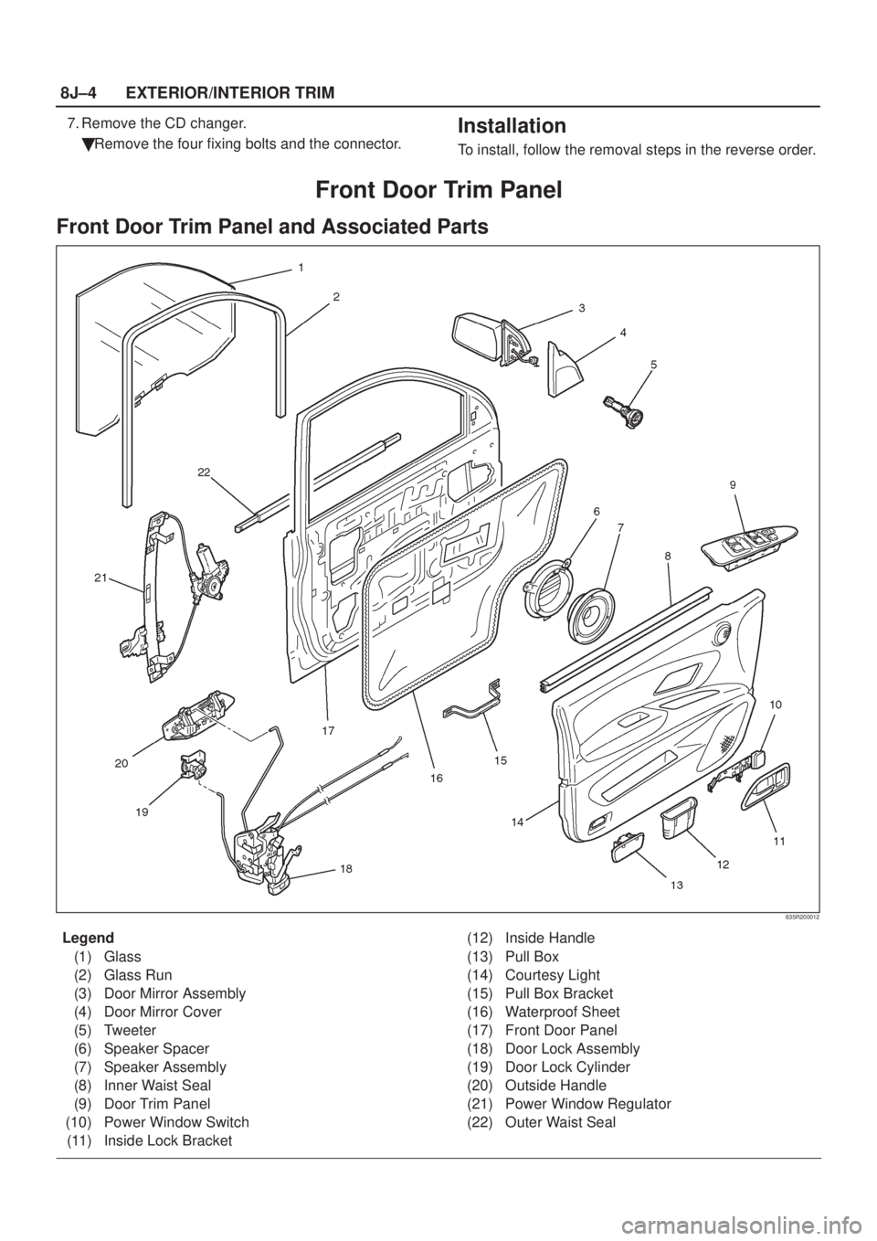
Front Door Trim Panel
Front Door Trim Panel and Associated Parts
635R200012
Legend
(1) Glass
(2) Glass Run
(3) Door Mirror Assembly
(4) Door Mirror Cover
(5) Tweeter
(6) Speaker Spacer
(7) Speaker Assembly
(8) Inner Waist Seal
(9) Door Trim Panel
(10) Power Window Switch
(11) Inside Lock Bracket(12) Inside Handle
(13) Pull Box
(14) Courtesy Light
(15) Pull Box Bracket
(16) Waterproof Sheet
(17) Front Door Panel
(18) Door Lock Assembly
(19) Door Lock Cylinder
(20) Outside Handle
(21) Power Window Regulator
(22) Outer Waist Seal
Page 1983 of 2100
EXTERIOR/INTERIOR TRIM8J±5
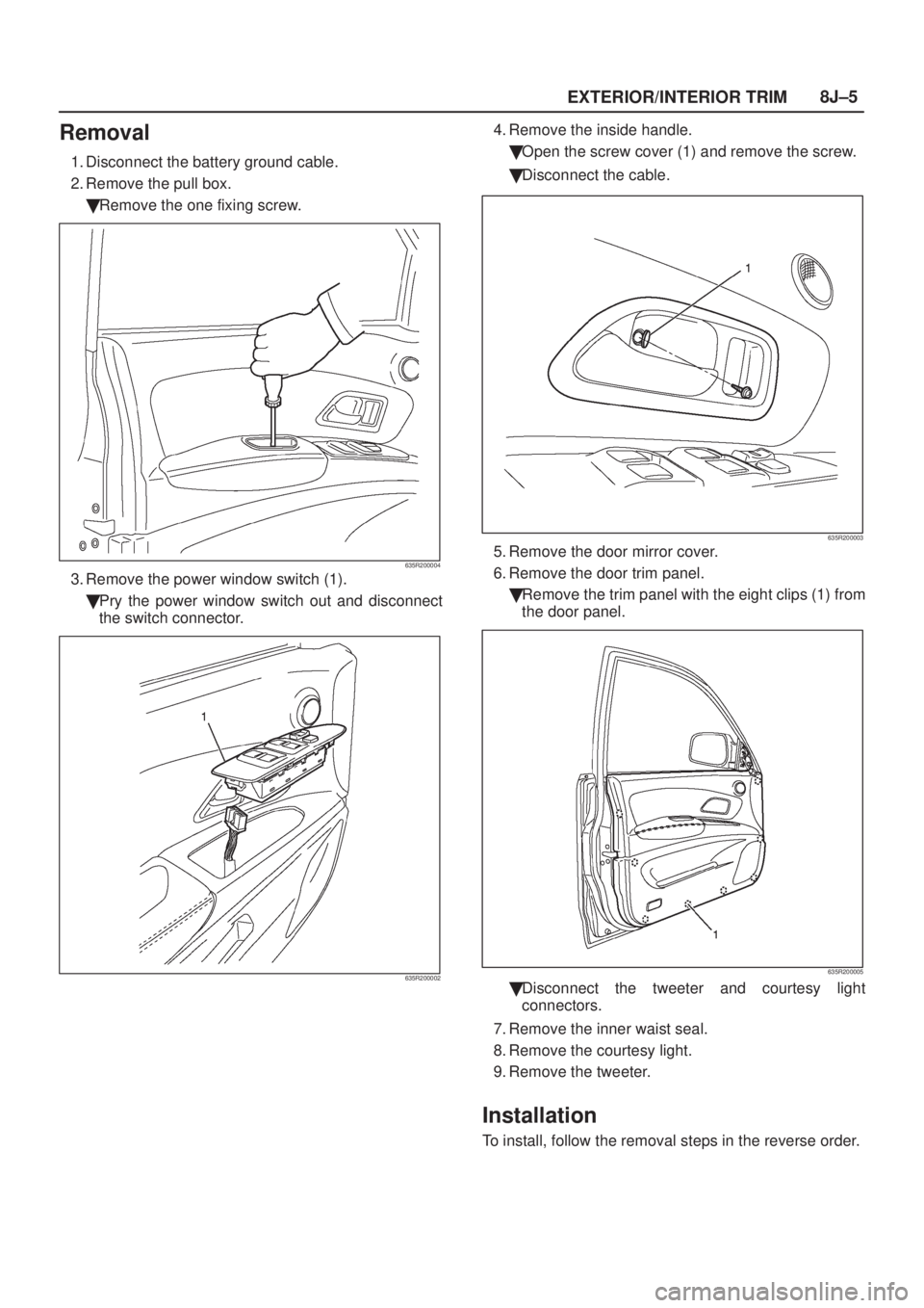
Removal
1. Disconnect the battery ground cable.
2. Remove the pull box.
�Remove the one fixing screw.
635R200004
3. Remove the power window switch (1).
�Pry the power window switch out and disconnect
the switch connector.
635R200002
4. Remove the inside handle.
�Open the screw cover (1) and remove the screw.
�Disconnect the cable.
635R200003
5. Remove the door mirror cover.
6. Remove the door trim panel.
�Remove the trim panel with the eight clips (1) from
the door panel.
635R200005
�Disconnect the tweeter and courtesy light
connectors.
7. Remove the inner waist seal.
8. Remove the courtesy light.
9. Remove the tweeter.
Installation
To install, follow the removal steps in the reverse order.
Page 1984 of 2100
8J±6EXTERIOR/INTERIOR TRIM
Rear Door Trim Panel
Rear Door Trim Panel and Associated Parts
655R200009
Legend
(1) Glass Run
(2) Glass
(3) Division Bar
(4) Fix Window Glass
(5) Power Window Regulator
(6) Outside Handle
(7) Door Lock Assembly
(8) Pull Box Bracket
(9) Speaker Spacer
(10) Speaker(11) Pull Box
(12) Door Trim Panel
(13) Courtesy Light
(14) Power Window Switch
(15) Inside Handle
(16) Inside Lock Bracket
(17) Inner Waist Seal
(18) Tweeter
(19) Waterproof Sheet
(20) Outer Waist Seal
(21) Rear Door Panel
Page 1985 of 2100
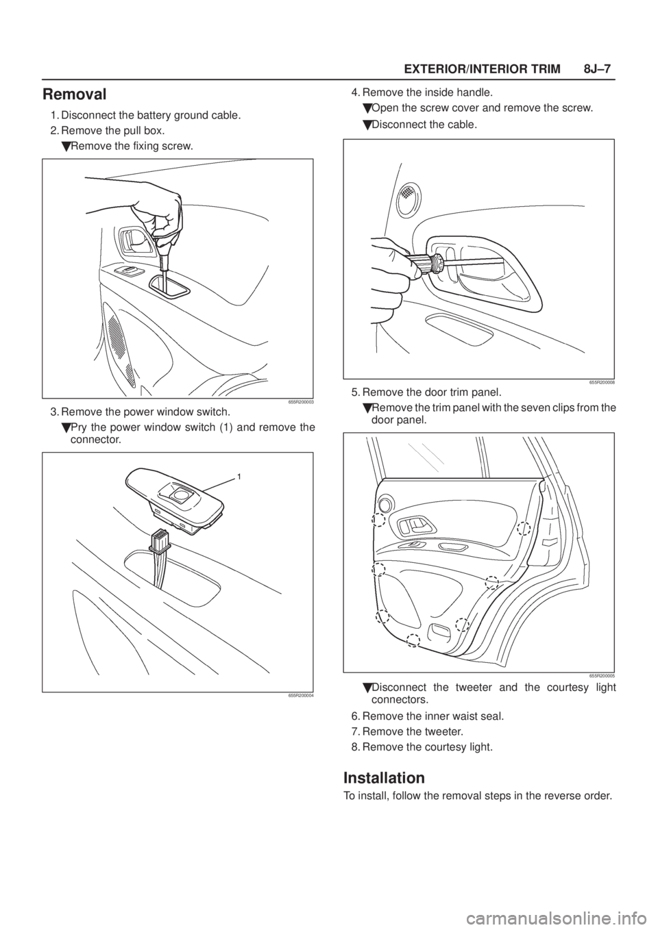
EXTERIOR/INTERIOR TRIM8J±7
Removal
1. Disconnect the battery ground cable.
2. Remove the pull box.
�Remove the fixing screw.
655R200003
3. Remove the power window switch.
�Pry the power window switch (1) and remove the
connector.
655R200004
4. Remove the inside handle.
�Open the screw cover and remove the screw.
�Disconnect the cable.
655R200008
5. Remove the door trim panel.
�Remove the trim panel with the seven clips from the
door panel.
655R200005
�Disconnect the tweeter and the courtesy light
connectors.
6. Remove the inner waist seal.
7. Remove the tweeter.
8. Remove the courtesy light.
Installation
To install, follow the removal steps in the reverse order.
Page 1999 of 2100

EXTERIOR/INTERIOR TRIM8J±21
Power Window System
General Description
The power window system consists of power window
switches and power window motors on driver and
passenger sides and power window relay. With the starter
switch in ªONº position, the battery voltage is supplied
through power window relay to the power window
switches on driver and passenger sides. Selection of up
or down switch changes the motor rotating direction to
open or close the window.
When the power window ªLOCKº switch on the driver side
is pressed, the power source for the other switches are
disconnected causing the power window operation to
seize.
Power Window Switch Driver Seat
Side
Removal
1. Disconnect the battery ground cable.
2. Remove the switch (1).
�Pull out the switch by pushing the spring with the tip
of a screwdriver.
�Disconnect the connector.
635R200002
Installation
To install, follow the removal steps in the reverse order.
Front Passenger Seat Side
Removal
1. Disconnect the battery ground cable.
2. Remove the switch (1).
�Pull out the switch by pushing the spring (2) with the
tip of a screwdriver.
�Disconnect the connector.
825R200025
Installation
To install, follow the removal steps in the reverse order.
Rear-Left and Right Sides
Removal
1. Disconnect the battery ground cable.
2. Remove the rear power window switch (1).
�Pull out the switch by pushing the spring with the tip
of a screwdriver.
�Disconnect the connector.
655R200004
Installation
To install, follow the removal steps in the reverse order.
Page 2000 of 2100
.
�Refer to the
Window Regulator and Glass")
8J±22EXTERIOR/INTERIOR TRIM
Power Window Motor
Driver Seat Side
Removal
1. Disconnect the battery ground cable.
2. Remove the window regulator assembly (2).
�Refer to the
Window Regulator and Glass removal
steps in Body Structure section.
3. Remove the power window motor (1).
�Remove three screws.
635R200007
Installation
To install, follow the removal steps in the reverse order.
Front Passenger Seat Side
Removal and Installation
Refer to the
Front Window Motor Ð Driver Seat side
removal and installation steps in this section.
Rear-Right Side
Removal
1. Disconnect the battery ground cable.
2. Remove the rear window regulator assembly (2).
�Refer to the
Rear Window Regulator and Glass
removal steps in Body Structure section.
3. Remove the power window motor (1).
�Remove three screws.
655R200006
Installation
To install, follow the removal steps in the reverse order.
Rear-Left Side
Removal and Installation
Refer to the
Rear Power Window Motor Ð Right Side
removal and installation steps in this section.
 Glass Run
(2) Glass
(3) Division Bar
(4) Fix Window Glass
(5) Power Window Regulator
(6")