Page 1932 of 2100
 Primer Coating Area (Glass side)
(2) Adhesive(3) Primer")
8F±56BODY STRUCTURE
Installation
To install, follow the removal steps in the reverse order,
noting the following points:
641R200003
Legend
(1) Primer Coating Area (Glass side)
(2) Adhesive(3) Primer Coating Area (Body panel side)
(4) Rear Quarter Glass
(5) Moulding
1. Clean the bonding surfaces of both the window glass
and body panel with a soft rag and white gasoline.
2. Apply the primer to the window glass and body panel.
�Apply the primer (Sun star # 435-40 or equivalent)
to the window glass side bonding surface as shown
in the figure.
�Apply the primer (Sun star # 435-95 or equivalent)
to the body side bonding surface.
3. Apply sealing adhesive to the window glass.
�Make sure that the primer has dried completely.
�Apply sealing adhesive (SunStar 555 or the
equivalent) to the circumference of the window
glass. There should be a 20 mm (0.79 in) overlap at
the lower front corner of the glass.
4. Attach the fastener tape and spacers to the points
shown in the illustration.
5. Attach the glass clips to the panel. Press the glass
into the panel until it adheres to the panel.
NOTE: Immediately wipe away any excess sealing
adhesive oozing from the panel and glass.6. Allow the assembly to dry for 24 hours (20~30�C).
7. Check to make sure that there is no water leakage
from the rear quarter glass.
Page 1934 of 2100
")
8F±58BODY STRUCTURE
7. Remove the tailgate glass assembly.
�Use a knife to cut through part of the adhesive
caulking material. Secure one end of a piece of
steel piano wire (0.02 inches in diameter) to a piece
of wood that can serve as a handle.
�Use a pair of needle nose pliers to insert the other
end of the piano wire through the adhesive caulking
material at the edge of the tailgate glass.
�Secure the other end of the piano wire to another
piece of wood.
�With the aid of an assistant, carefully move the
piano wire with a sawing motion to cut through the
adhesive caulking material around the entire
circumference of the tailgate glass.
�Attach some cloth tape (1) on the body for
protecting the painting surface.
607RW012
�Clean the remaining adhesive caulking material
from the area of the body which holds the
tailgateglass.
Installation
To install, follow the removal steps in reverse order, noting
the following points:
1. Clean the bonding surfaces of both the tailgate glass
and tailgate with a soft rag and white gasoline.
2. Apply the primer to the tailgate glass and tailgate.
�Apply the primer (Sun star # 435-40 or equivalent)
to the tailgate side bonding surface.
�Apply the primer (Sun star # 435-95 or equivalent)
to the tailgate side bonding surface.
NOTE: Apply an adhesive 3 minutes or more but with in
24 hours after the application of primer. If more than 24
hours have passed, reapply primer.
Primer should be handled as following:
1. Use the primer manufactured 3 months or less
ago having been kept in an refrigerator.
2. Wipe off primer-stains on positions other than
require application.3. Stir the primer for a minute or more before use.
3. Apply the adhesive to the tailgate glass.
�After drying primer completely, apply a sealing
adhesive (Sun star # 555 or equivalent) along the
edge of the glass so that the sealing adhesive has a
20 mm (0.79 in) junction at middle of the base of the
glass.
NOTE: Adhesive an adhesive 3 minutes or more but with
in 24 hours after the application of primer. If more than 24
hours have passed, reapply primer.
Primer should be handled as follows:
1. Use the adhesive manufactured 3 months or less
ago.
2. Wipe off adhesive-stains on positions other than
requires application.
4. Install the tailgate glass.
�Set the window (adhesive applied) to the tailgate
window frame. Carefully align the clips (bottom
corners) and fasteners (top corners).
NOTE: Affix the glass within 5 minutes of application.
607RS017
5. Install tailgate wiper arm.
Page 1952 of 2100
8H±2SECURITY AND LOCKS
Front Door Lock Assembly
Front Door Lock Assembly and Associated Parts
635R200008
Legend
(1) Door Mirror Cover
(2) Power Window Switch
(3) Door Trim Panel
(4) Inside Lock Bracket
(5) Inside Handle(6) Pull Box
(7) Pull Box Bracket
(8) Waterproof Sheet
(9) Door Lock Assembly
(10) Door Lock Cylinder
(11) Outside Handle
Removal
1. Disconnect the battery ground cable.
2. Remove the pull box.
�Remove the one fixing screw.
635R200004
Page 1953 of 2100
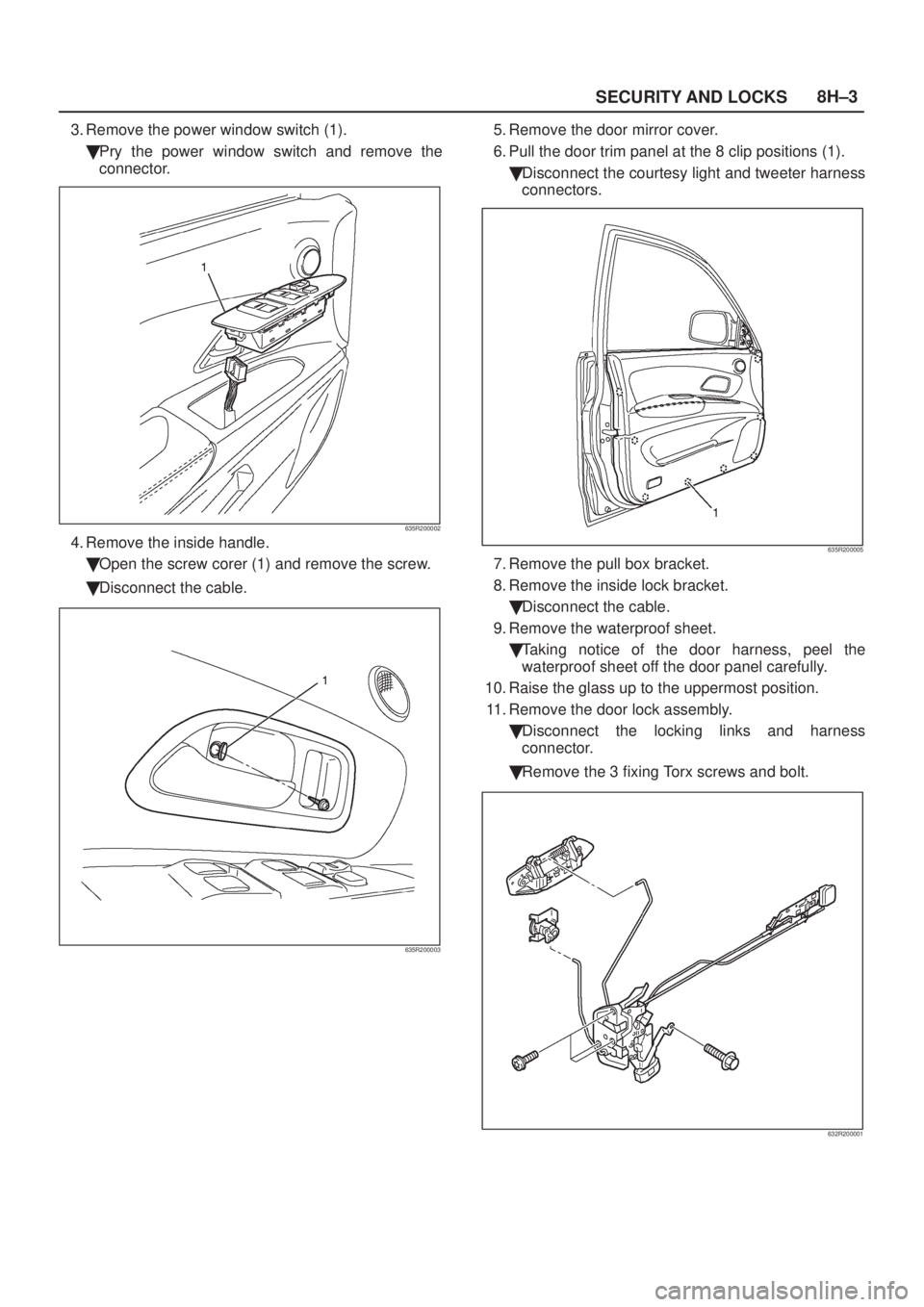
SECURITY AND LOCKS8H±3
3. Remove the power window switch (1).
�Pry the power window switch and remove the
connector.
635R200002
4. Remove the inside handle.
�Open the screw corer (1) and remove the screw.
�Disconnect the cable.
635R200003
5. Remove the door mirror cover.
6. Pull the door trim panel at the 8 clip positions (1).
�Disconnect the courtesy light and tweeter harness
connectors.
635R200005
7. Remove the pull box bracket.
8. Remove the inside lock bracket.
�Disconnect the cable.
9. Remove the waterproof sheet.
�Taking notice of the door harness, peel the
waterproof sheet off the door panel carefully.
10. Raise the glass up to the uppermost position.
11. Remove the door lock assembly.
�Disconnect the locking links and harness
connector.
�Remove the 3 fixing Torx screws and bolt.
632R200001
Page 1955 of 2100
 Door Mirror Cover
(2) Power Window Switch
(3) Door Trim Panel
(4) Inside Lock Bracket
(5) I")
SECURITY AND LOCKS8H±5
Front Outside Handle
Front Outside Handle and Associated Parts
635R200008
Legend
(1) Door Mirror Cover
(2) Power Window Switch
(3) Door Trim Panel
(4) Inside Lock Bracket
(5) Inside Handle(6) Pull Box
(7) Pull Box Bracket
(8) Waterproof Sheet
(9) Door Lock Assembly
(10) Door Locking Cylinder
(11) Outside Handle
Removal
1. Disconnect the battery ground cable.
2. Remove the door trim panel.
�Refer to
Front Door Lock Assembly in this section.
3. Remove the waterproof sheet.
�Taking notice of the door harness, peel the
waterproof sheet off the door panel carefully.
4. Disconnect the locking links and remove the outside
handle.
5. Remove the fixing clip to remove the door lock
cylinder.
Installation
To install, follow the removal steps in the reverse order,
noting the following points:
1. Be sure to install the door lock cylinder at a specified
angle to the outside handle.
2. Check for smooth outside handle and lock cylinder
operation.
3. Tighten the outside handle fixing bolts to the specified
torque.
Torque 7 N´m (61 Ib in)
Page 1956 of 2100
8H±6SECURITY AND LOCKS
Rear Door Lock Assembly
Rear Door Lock Assembly and Associated Parts
655R200007
Legend
(1) Outside Handle
(2) Door Lock Assembly
(3) Pull Box Bracket
(4) Pull Box(5) Door Trim Panel
(6) Power Window Switch
(7) Inside Handle
(8) Inside Lock Bracket
(9) Waterproof Sheet
Removal
1. Disconnect the battery ground cable.
2. Remove the pull box.
�Remove the fixing screw.
655R200003
Page 1957 of 2100
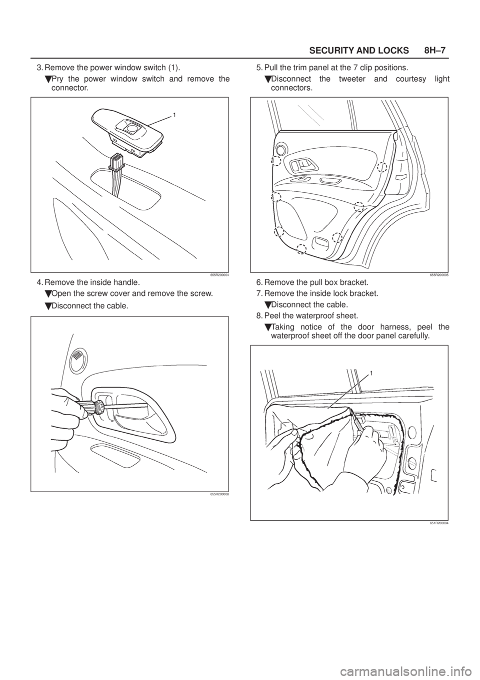
SECURITY AND LOCKS8H±7
3. Remove the power window switch (1).
�Pry the power window switch and remove the
connector.
655R200004
4. Remove the inside handle.
�Open the screw cover and remove the screw.
�Disconnect the cable.
655R200008
5. Pull the trim panel at the 7 clip positions.
�Disconnect the tweeter and courtesy light
connectors.
655R200005
6. Remove the pull box bracket.
7. Remove the inside lock bracket.
�Disconnect the cable.
8. Peel the waterproof sheet.
�Taking notice of the door harness, peel the
waterproof sheet off the door panel carefully.
651R200004
Page 1959 of 2100
SECURITY AND LOCKS8H±9
Rear Outside Handle
Rear Outside Handle and Associated Parts
655R200007
Legend
(1) Outside Handle
(2) Door Lock Assembly
(3) Pull Box Bracket
(4) Pull Box(5) Door Trim Panel
(6) Power Window Switch
(7) Inside Handle
(8) Inside Lock Bracket
(9) Waterproof Sheet
Removal
1. Disconnect the battery ground cable.
2. Remove the door trim panel.
�Refer to
Rear Door Lock Assembly in this section.
3. Peel the waterproof sheet.
�Taking notice of the door harness, peel the
waterproof sheet off the door panel carefully.
4. Disconnect the locking link and remove fixing bolts to
remove the outside handle.
Installation
To install, follow the removal steps in the reverse order,
noting the following points.
1. Check that the outside handle operates smoothly.
2. Tighten the outside handle fixing bolts to the specified
torque.
Torque 7 N´m (61 Ib in)
 Door Mirror Cover
(2) Power Window Switch
(3) Door Trim Panel
(4) Inside Lock Brack")
 Outside Handle
(2) Door Lock Assembly
(3) Pull Box Bracket
(4) Pull Box(5) Door Trim")
 Outside Handle
(2) Door Lock Assembly
(3) Pull Box Bracket
(4) Pull Box(5) Door Trim Panel
(6")