Page 1908 of 2100
8F±32BODY STRUCTURE
General Description (Body)
This publication contains essential removal, installation,
adjustment and maintenance procedures.
Instrument Panel Assembly
Parts Location
740R200024
Legend
(1) Cross Beam
(2) Vent Duct Assembly
(3) Instrument Panel Stay
(4) Passenger Air Bag
(5) Passenger Air Bag Cover
(6) Dash Side Trim Panel (RH)
(7) Instrument Upper Reinforcement
(8) Glove Box Side Reinforcement
(9) Passenger Lower Bracket
(10) Glove Box
(11) Display Unit
(12) Audio Kit(13) Front Console Assembly
(14) Knee Pad
(15) Center Cluster Assembly
(16) Cluster Upper Cover
(17) Instrument Panel Driver Lower Cover
Assembly
(18) Driver Knee Bolster Assembly
(19) Dash Side Trim Panel (LH)
(20) Meter Cluster Assembly
(21) Instrument Panel Center Reinforcement
(22) Meter Assembly
(23) Instrument Panel Assembly
(24) Instrument Harness Assembly
Page 1909 of 2100

8F±33 BODY STRUCTURE
Removal
CAUTION: F o r p recautions on installation or
removal of SRS ± air bag system, refer to
Supplemental Restraint System (SRS) ± AIR BAG in
Restraint section.
1. Disconnect the battery ground cable.
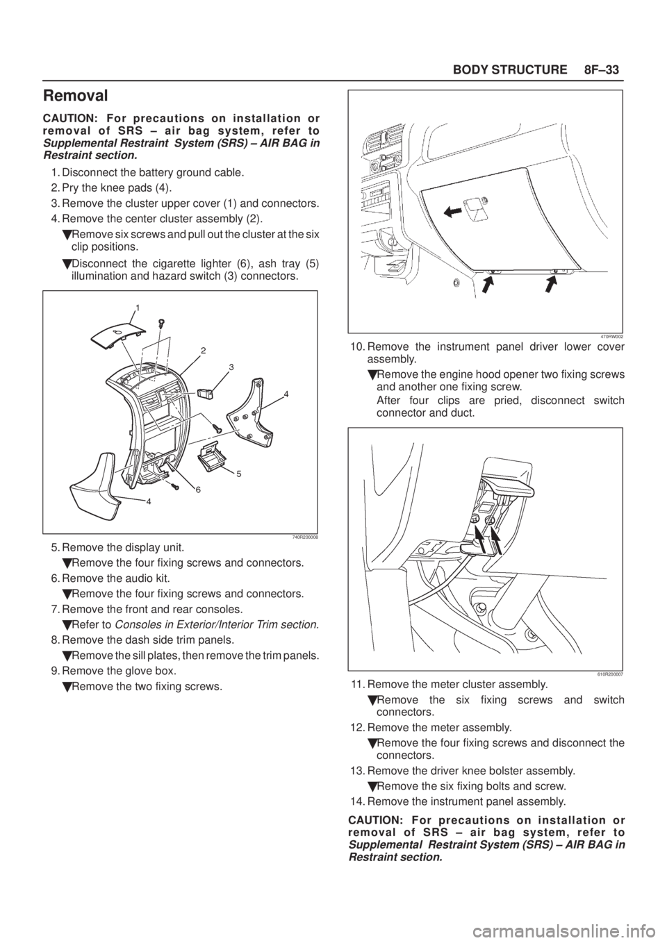
2. Pry the knee pads (4).
3. Remove the cluster upper cover (1) and connectors.
4. Remove the center cluster assembly (2).
�Remove six screws and pull out the cluster at the six
clip positions.
�Disconnect the cigarette lighter (6), ash tray (5)
illumination and hazard switch (3) connectors.
740R200008
5. Remove the display unit.
�Remove the four fixing screws and connectors.
6. Remove the audio kit.
�Remove the four fixing screws and connectors.
7. Remove the front and rear consoles.
�Refer to
Consoles in Exterior/Interior Trim section.
8. Remove the dash side trim panels.
�Remove the sill plates, then remove the trim panels.
9. Remove the glove box.
�Remove the two fixing screws.
470RW002
10. Remove the instrument panel driver lower cover
assembly.
�Remove the engine hood opener two fixing screws
and another one fixing screw.
After four clips are pried, disconnect switch
connector and duct.
610R200007
11. Remove the meter cluster assembly.
�Remove the six fixing screws and switch
connectors.
12. Remove the meter assembly.
�Remove the four fixing screws and disconnect the
connectors.
13. Remove the driver knee bolster assembly.
�Remove the six fixing bolts and screw.
14. Remove the instrument panel assembly.
CAUTION: F o r p recautions on installation or
removal of SRS ± air bag system, refer to
Supplemental Restraint System (SRS) ± AIR BAG in
Restraint section.
Page 2017 of 2100

SUPPLEMENTAL RESTRAINT SYSTEM9J±3
System Description
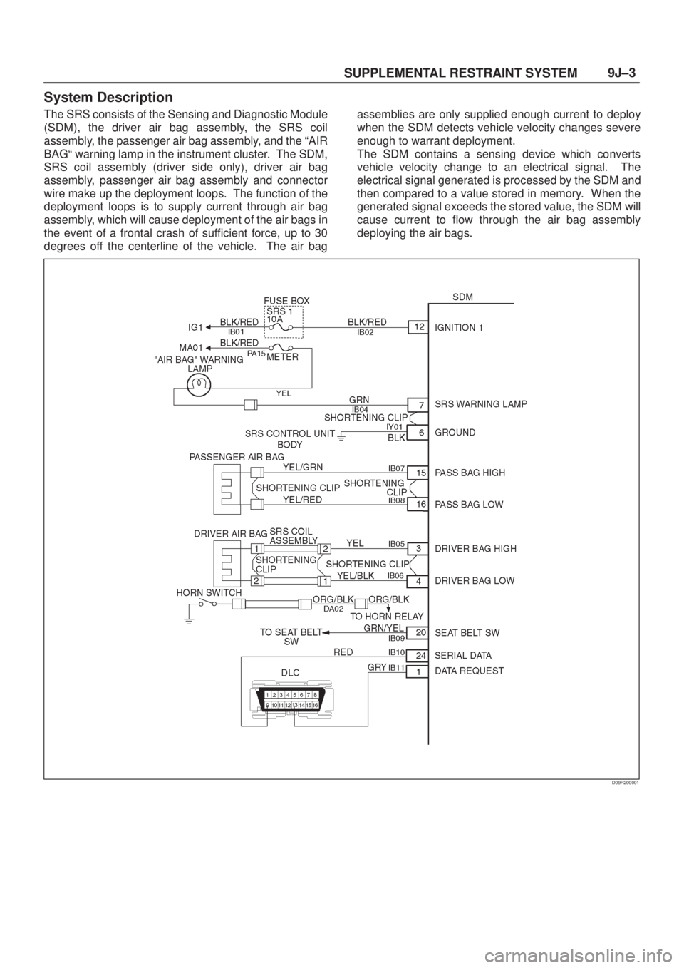
The SRS consists of the Sensing and Diagnostic Module
(SDM), the driver air bag assembly, the SRS coil
assembly, the passenger air bag assembly, and the ªAIR
BAGª warning lamp in the instrument cluster. The SDM,
SRS coil assembly (driver side only), driver air bag
assembly, passenger air bag assembly and connector
wire make up the deployment loops. The function of the
deployment loops is to supply current through air bag
assembly, which will cause deployment of the air bags in
the event of a frontal crash of sufficient force, up to 30
degrees off the centerline of the vehicle. The air bagassemblies are only supplied enough current to deploy
when the SDM detects vehicle velocity changes severe
enough to warrant deployment.
The SDM contains a sensing device which converts
vehicle velocity change to an electrical signal. The
electrical signal generated is processed by the SDM and
then compared to a value stored in memory. When the
generated signal exceeds the stored value, the SDM will
cause current to flow through the air bag assembly
deploying the air bags.
D09R200001
Page 2060 of 2100

RESTRAINT CONTROL SYSTEM 9J1±10
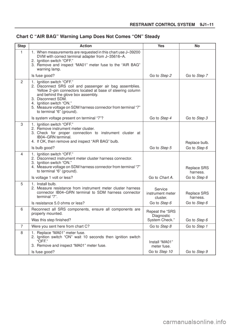
Chart C ªAIR BAGº Warning Lamp Does Not Comes ªONº Steady
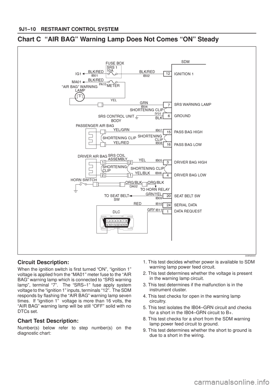
D09R200001
Circuit Description:
When the ignition switch is first turned ªONº, ªignition 1º
voltage is applied from the ªMA01º meter fuse to the ªAIR
BAGº warning lamp which is connected to ªSRS warning
lampº, terminal ª7º. The ªSRS±1º fuse apply system
voltage to the ªignition 1º inputs, terminals ª12º. The SDM
responds by flashing the ªAIR BAGº warning lamp seven
times. If ªignition 1º voltage is more than 16 volts, the
ªAIR BAGº warning lamp will be still ªOFFº solid with no
DTCs set.
Chart Test Description:
Number(s) below refer to step number(s) on the
diagnostic chart:1. This test decides whether power is available to SDM
warning lamp power feed circuit.
2. This test determines whether the voltage is present
in the warning lamp circuit.
3. This test determines if the malfunction is in the
instrument cluster.
4. This test checks for open in the warning lamp
circuitry.
5. This test isolates the IB04±GRN circuit and checks
for a short in the IB04±GRN circuit to B+.
8. This test checks for a short from the SDM warning
lamp power feed circuit to ground.
9. This test determines whether the short to ground is
due to a short in the wiring.
Page 2061 of 2100

9J1±11
RESTRAINT CONTROL SYSTEM
Chart C ªAIR BAGº Warning Lamp Does Not Comes ªONº Steady
StepActionYe sNo
11. When measurements are requested in this chart use J±39200
DVM with correct terminal adapter from J±35616±A.
2. Ignition switch ªOFF.º
3. Remove and inspect ªMA01º meter fuse to the ªAIR BAGº
warning lamp.
Is fuse good?
Go to Step 2 Go to Step 7
21. Ignition switch ªOFF.º
2. Disconnect SRS coil and passenger air bag assemblies.
Yellow 2±pin connectors located at base of steering column
and behind the glove box assembly.
3. Disconnect SDM.
4. Ignition switch ªON.º
5. Measure voltage on SDM harness connector from terminal ª7º
to terminal ª6º (ground).
Is system voltage present on terminal ª7º?
Go to Step 4 Go to Step 3
31. Ignition switch ªOFF.º
2. Remove instrument meter cluster.
3. Check for proper connection to instrument cluster at
IB04±GRN terminal.
4. If OK, then remove and inspect ªAIR BAGº bulb.
Is bulb good?
Go to Step 5
Replace bulb.
Go to
Step 6
41. Ignition switch ªOFF.º
2. Disconnect instrument meter cluster harness connector.
3. Ignition switch ªON.º
4. Measure voltage on SDM harness connector from terminal ª7º
to terminal ª6º (ground).
Is voltage 1 volt or less?
Go to Chart A.
Replace SRS
harness.
Go to
Step 6
51. Install bulb.
2. Measure resistance from instrument meter cluster harness
connector IB04±GRN terminal to SDM harness connector
terminal ª7º.
Is resistance 5.0 ohms or less?
Service
instrument meter
cluster.
Go to
Step 6
Replace SRS
harness.
Go to
Step 6
6Reconnect all SRS components, ensure all components are
properly mounted.
Was this step finished?Repeat the ªSRS
Diagnostic
System Check.º
Go to Step 6
7Were you sent here from chart C?Go to Step 8 Go to Step 1
81. Replace ªMA01º meter fuse.
2. Ignition switch ªONº wait 10 seconds then ignition switch
ªOFF.º
3. Remove and inspect ªMA01º meter fuse.
Is fuse good?
Install ªMA01º
meter fuse.
Go to
Step 10 Go to Step 9
Page 2099 of 2100
10A±3
CRUISE CONTROL SYSTEM
Powertrain Control Module (PCM)
Removal and Installation
Refer to Powertrain Control Module (PCM) in Engine
section.
Mode Switch
Removal and Installation
Refer to Mode Switch removal and installation steps in
Automatic Transmission section.
Cruise Control Main Switch
Removal
1. Disconnect the battery ground cable.
2. Remove the meter cluster assembly (1).
�Refer to
Instrument Panel Assembly in Body
Structure section.
3. Remove the cruise control main switch (2).
�Disconnect the switch connector.
�Push the lock from the back side of the instrument
panel cluster assembly.
825R100019
Installation
To install, follow the removal steps in the reverse order.
Cruise Control Switch (Combination Switch)
Removal and Installation
Refer to Lighting Switch (Combination Switch) removal
and installation steps in Lighting System section.