Page 1790 of 2100
8A±14LIGHTING SYSTEM
Vanity Mirror Illumination Light Bulb
Removal
1. Disconnect the battery ground cable.
2. Remove the lens (1).
3. Remove the bulb (2).
805R200004
Installation
To install, follow the removal steps in the reverse order.
Switch Unit Assembly Illumination Light Bulb
(Power/Winter & Intelligent Suspension Switch)
Removal
1. Disconnect the battery ground cable.
2. Remove the center cluster assembly.
�Refer to
Instrument Panel Assembly in Body
Structure
section.
3. Remove the audio.
�Refer to
Audio in Entertainment section.
4. Remove the illumination light bulb.
825R200036
Installation
To install, follow the removal steps in the reverse order.
Page 1791 of 2100
LIGHTING SYSTEM8A±15
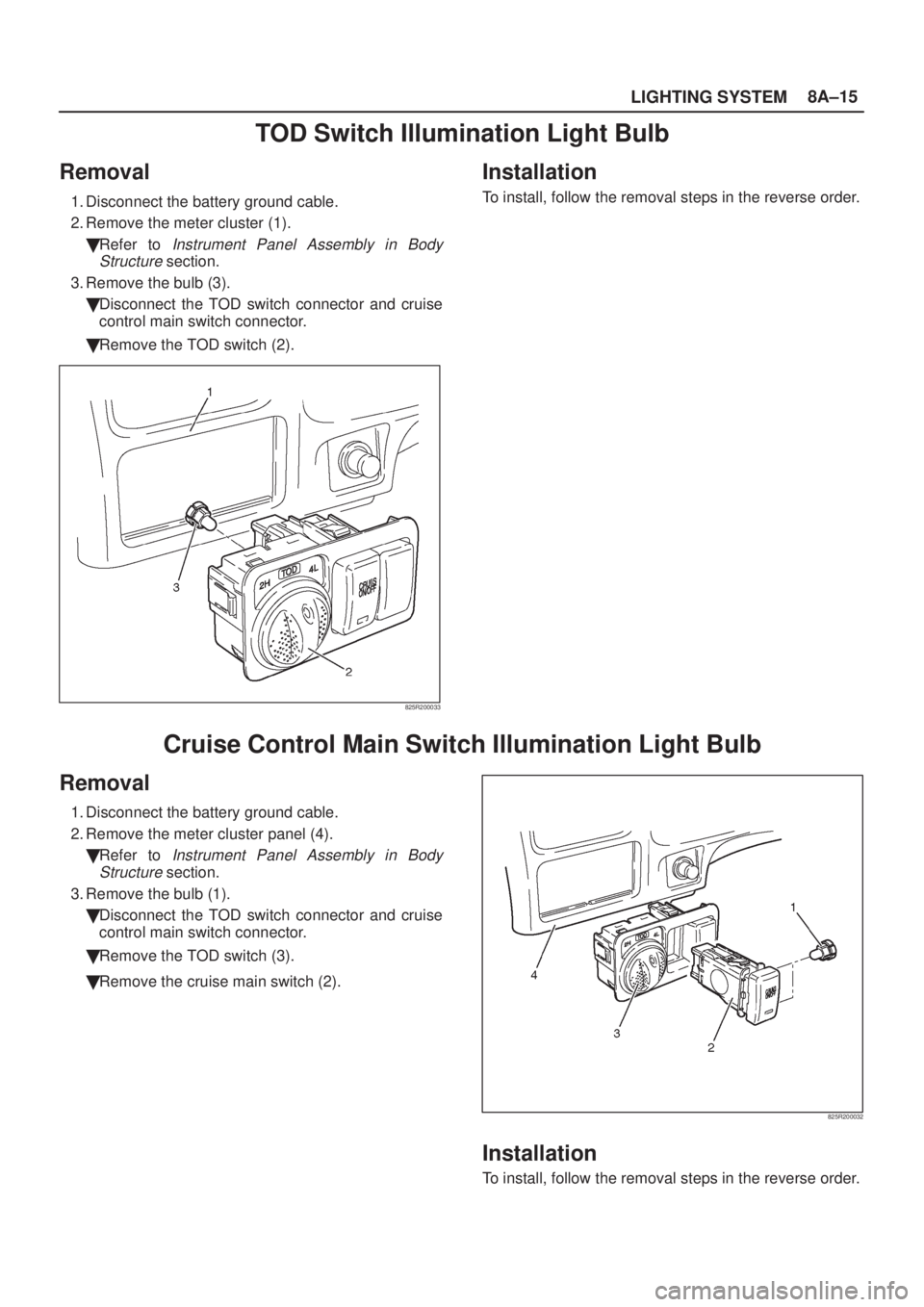
TOD Switch Illumination Light Bulb
Removal
1. Disconnect the battery ground cable.
2. Remove the meter cluster (1).
�Refer to
Instrument Panel Assembly in Body
Structure
section.
3. Remove the bulb (3).
�Disconnect the TOD switch connector and cruise
control main switch connector.
�Remove the TOD switch (2).
825R200033
Installation
To install, follow the removal steps in the reverse order.
Cruise Control Main Switch Illumination Light Bulb
Removal
1. Disconnect the battery ground cable.
2. Remove the meter cluster panel (4).
�Refer to
Instrument Panel Assembly in Body
Structure
section.
3. Remove the bulb (1).
�Disconnect the TOD switch connector and cruise
control main switch connector.
�Remove the TOD switch (3).
�Remove the cruise main switch (2).
825R200032
Installation
To install, follow the removal steps in the reverse order.
Page 1795 of 2100
LIGHTING SYSTEM8A±19
Key Remind Switch (Starter Switch)
Removal and Installation
Refer to Lock Cylinder in Steering section.
Hazard Warning Light Switch
Removal
1. Disconnect the battery ground cable.
2. Remove the center cluster assembly (1).
�Refer to
Instrument Panel Assembly in Body
Structure
section.
3. Remove the hazard warning switch (2).
�Disconnect the switch connector.
�To remove the switch, push the lock from the back
side of the center cluster assembly.
825R200026
Installation
To install, follow the removal steps in the reverse order.
Page 1796 of 2100
8A±20LIGHTING SYSTEM
Stoplight Switch
Removal and Installation
Refer to Stoplight Switch in Brake section.
Turn Signal Light Switch (Combination Switch)
Removal and Installation
Refer to Combination Switch in Steering section.
Illumination Controller
Removal
1. Disconnect the battery ground cable.
2. Remove the meter cluster panel cover assembly (2).
�Refer to
Instrument Panel Assembly in Body
Structure
section.
3. Remove the illumination controller (1).
�Disconnect the controller connector.
�Remove the controller knob (4).
�Remove the nut (3).
�Remove the controller from the back side of the
meter cluster panel assembly.
825R200027
Installation
To install, follow the removal steps in the reverse order.
Page 1814 of 2100
8C±2ENTERTAINMENT
Cigarette Lighter
General Description
When the cigarette lighter is pushed in with the starter
switch at either ªACCº or ªONº position, a circuit is formed
in the cigarette lighter case to heat the lighter coil.
The cigarette lighter springs back to its original position
after the lighter coil is heated.
Removal
1. Disconnect the battery ground cable.
2. Remove the center cluster assembly (1).
�Refer to
Instrument Panel Assembly in Body
Structure section.
3. Remove the cigarette lighter assembly (2).
�Disconnect the connectors.
�Remove the socket (3) and nut (4).
826R200012
Installation
To install, follow the removal steps in the reverse order,
noting the following point:
1. When installing the bezel, align the projected portion
of the socket with the notch of the bezel.
Page 1817 of 2100
ENTERTAINMENT8C±5
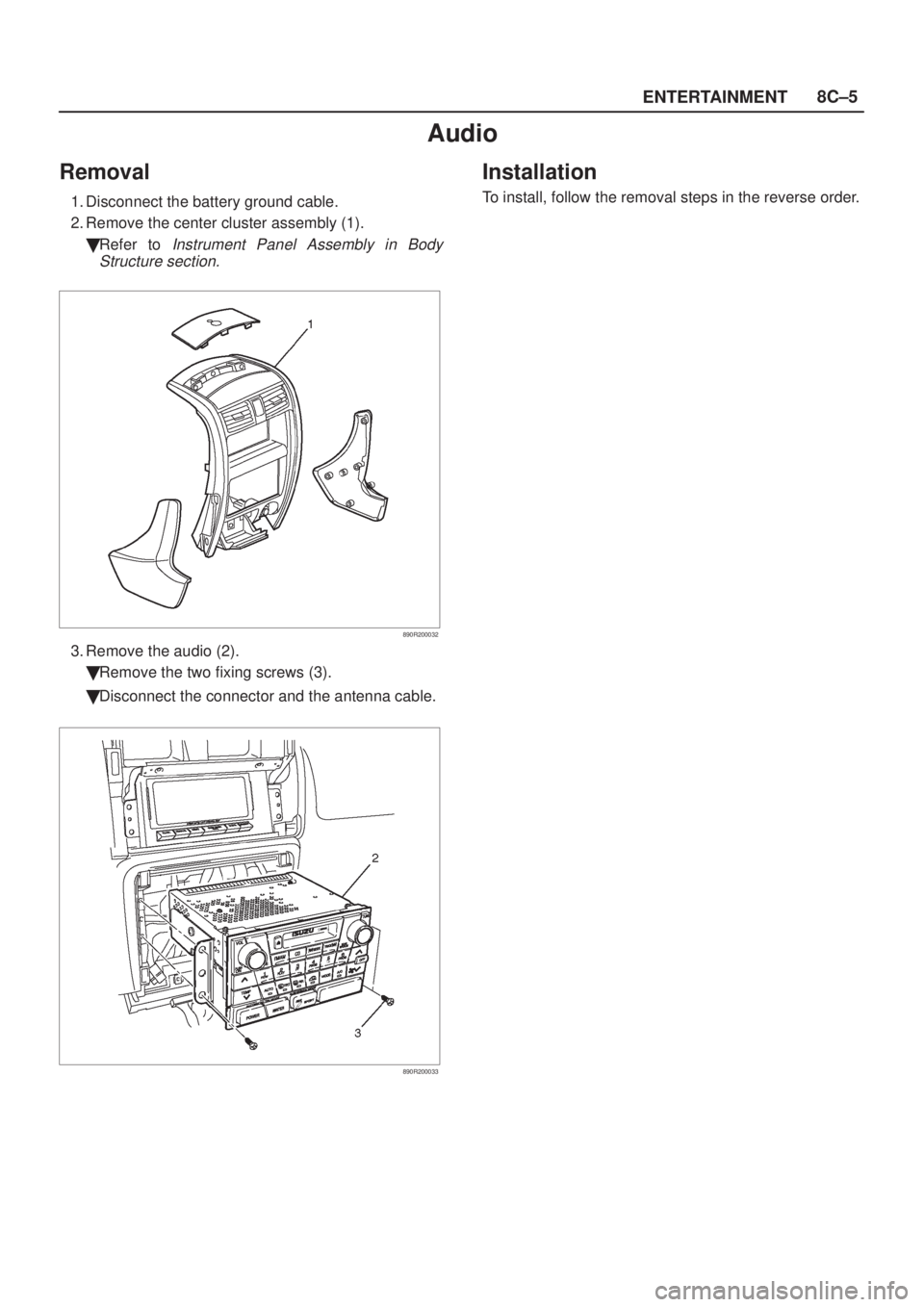
Audio
Removal
1. Disconnect the battery ground cable.
2. Remove the center cluster assembly (1).
�Refer to
Instrument Panel Assembly in Body
Structure section.
890R200032
3. Remove the audio (2).
�Remove the two fixing screws (3).
�Disconnect the connector and the antenna cable.
890R200033
Installation
To install, follow the removal steps in the reverse order.
Page 1820 of 2100
8C±8ENTERTAINMENT
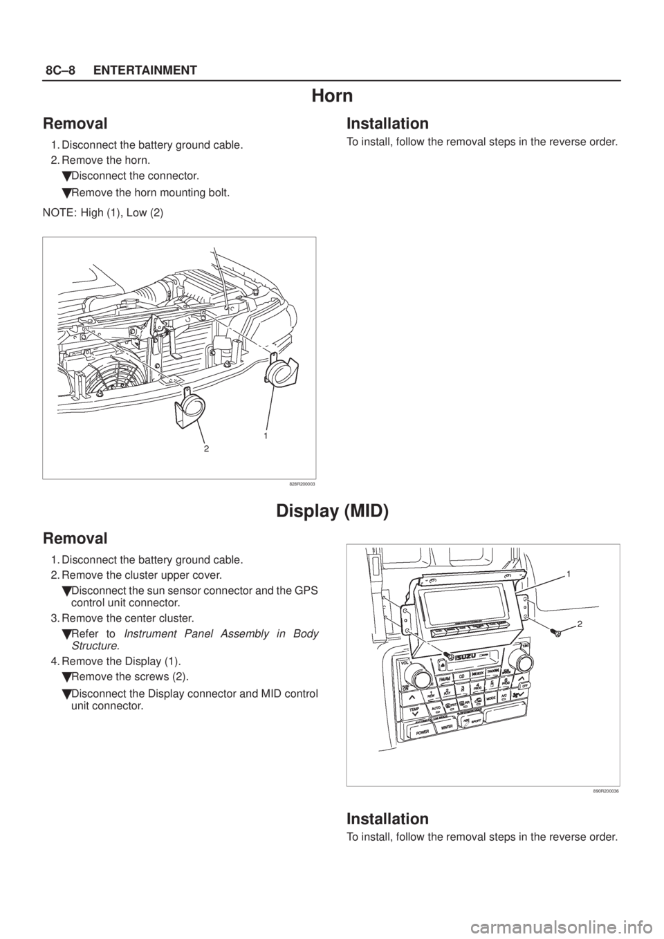
Horn
Removal
1. Disconnect the battery ground cable.
2. Remove the horn.
�Disconnect the connector.
�Remove the horn mounting bolt.
NOTE: High (1), Low (2)
828R200003
Installation
To install, follow the removal steps in the reverse order.
Display (MID)
Removal
1. Disconnect the battery ground cable.
2. Remove the cluster upper cover.
�Disconnect the sun sensor connector and the GPS
control unit connector.
3. Remove the center cluster.
�Refer to
Instrument Panel Assembly in Body
Structure.
4. Remove the Display (1).
�Remove the screws (2).
�Disconnect the Display connector and MID control
unit connector.
890R200036
Installation
To install, follow the removal steps in the reverse order.
Page 1872 of 2100
8E±6METER AND GAUGE
Removal
1. Disconnect the battery ground cable.
2. Remove the Dash Side Trim Panel ±LH.
3. Remove the lower cover Assembly(2).
�Refer to
Instrument Panel Assembly in Body
Structure
section.
4. Remove the meter cluster Assembly(1).
�Refer to
Instrument Panel Assembly in Body
Structure
section.
821R200020
5. Remove the meter assembly(3).
�Remove four fixing screws.
�Disconnect the meter connectors.
825RW197
CAUTION: The removed meter assembly should be
placed upright or with its face side up.
Installation
To install, follow the removal steps in the reverse order.
Warning Light Bulb and Indicator Light Bulb
Removal
1. Disconnect the battery ground cable.
2. Remove the meter assembly.
�Refer to
Meter Assembly in this section.
3. Remove the bulb.
�Hold the bulb socket by hand, rotate it
counterclockwise and pull it out.
Installation
To install, follow the removal steps in the reverse order.
.
3. Remove the bulb (2).
805R200004
Installation
To install, follow t")

Removal and Installation
Refer to Lock Cylinder in Steering section.
Hazard Warning Light Switch
Removal
1. Disconnect the battery ground cable")

Removal and Installation
Refer to Combination")