Page 701 of 2100
5C±21 POWER±ASSISTED BRAKE SYSTEM
Fluid Reservoir Tank
Fluid Reservoir Tank and Associated Parts
330RW003
Legend
(1) Fluid Reservoir
(2) Electrical Connector(3) O±ring
(4) Retainer
Removal
NOTE: Before removing the fluid reservoir, remove the
brake fluid from the fluid reservoir.
1. Disconnect electrical connector.
2. Remove retainer (1).
330RW004
3. Remove fluid reservoir and the fluid level sensor built
into the fluid reservoir. The fluid level sensor cannot
be removed for servicing.
4. Remove O±ring.
Installation
To install, follow the removal steps in the reverse order,
noting the following points:
1. O±ring (1) must be set onto the fluid reservoir (2),
before installing fluid reservoir.
330RW005
Page 702 of 2100

5C±22
POWER±ASSISTED BRAKE SYSTEM
Master Cylinder Assembly
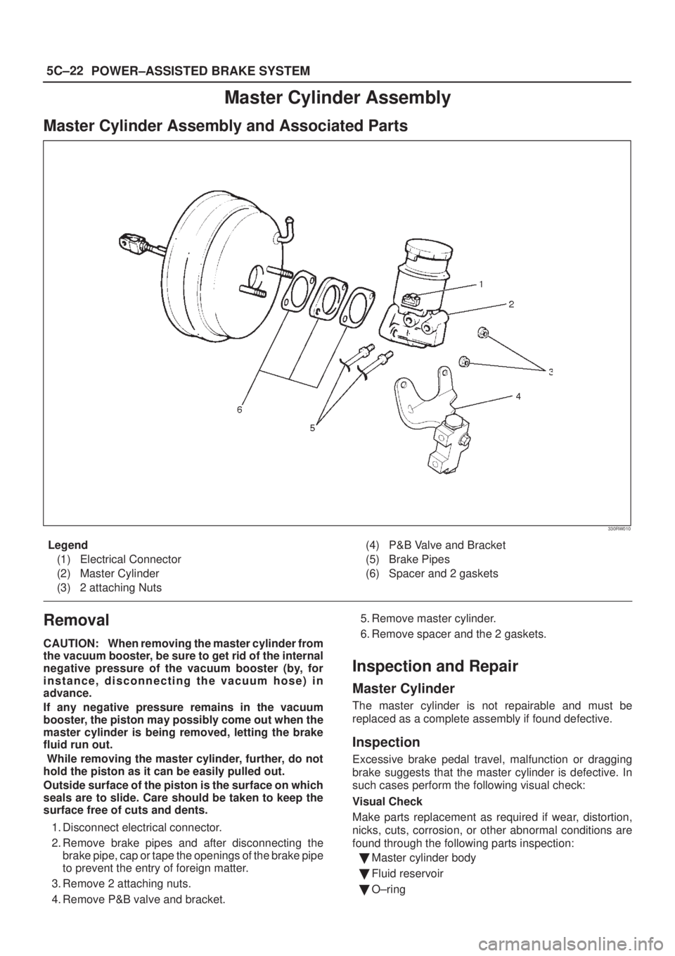
Master Cylinder Assembly and Associated Parts
330RW010
Legend
(1) Electrical Connector
(2) Master Cylinder
(3) 2 attaching Nuts(4) P&B Valve and Bracket
(5) Brake Pipes
(6) Spacer and 2 gaskets
Removal
CAUTION: When removing the master cylinder from
the vacuum booster, be sure to get rid of the internal
negative pressure of the vacuum booster (by, for
instance, disconnecting the vacuum hose) in
advance.
If any negative pressure remains in the vacuum
booster, the piston may possibly come out when the
master cylinder is being removed, letting the brake
fluid run out.
While removing the master cylinder, further, do not
hold the piston as it can be easily pulled out.
Outside surface of the piston is the surface on which
seals are to slide. Care should be taken to keep the
surface free of cuts and dents.
1. Disconnect electrical connector.
2. Remove brake pipes and after disconnecting the
brake pipe, cap or tape the openings of the brake pipe
to prevent the entry of foreign matter.
3. Remove 2 attaching nuts.
4. Remove P&B valve and bracket.5. Remove master cylinder.
6. Remove spacer and the 2 gaskets.
Inspection and Repair
Master Cylinder
The master cylinder is not repairable and must be
replaced as a complete assembly if found defective.
Inspection
Excessive brake pedal travel, malfunction or dragging
brake suggests that the master cylinder is defective. In
such cases perform the following visual check:
Visual Check
Make parts replacement as required if wear, distortion,
nicks, cuts, corrosion, or other abnormal conditions are
found through the following parts inspection:
�Master cylinder body
�Fluid reservoir
�O±ring
Page 705 of 2100

5C±25 POWER±ASSISTED BRAKE SYSTEM
Vacuum Booster Assembly
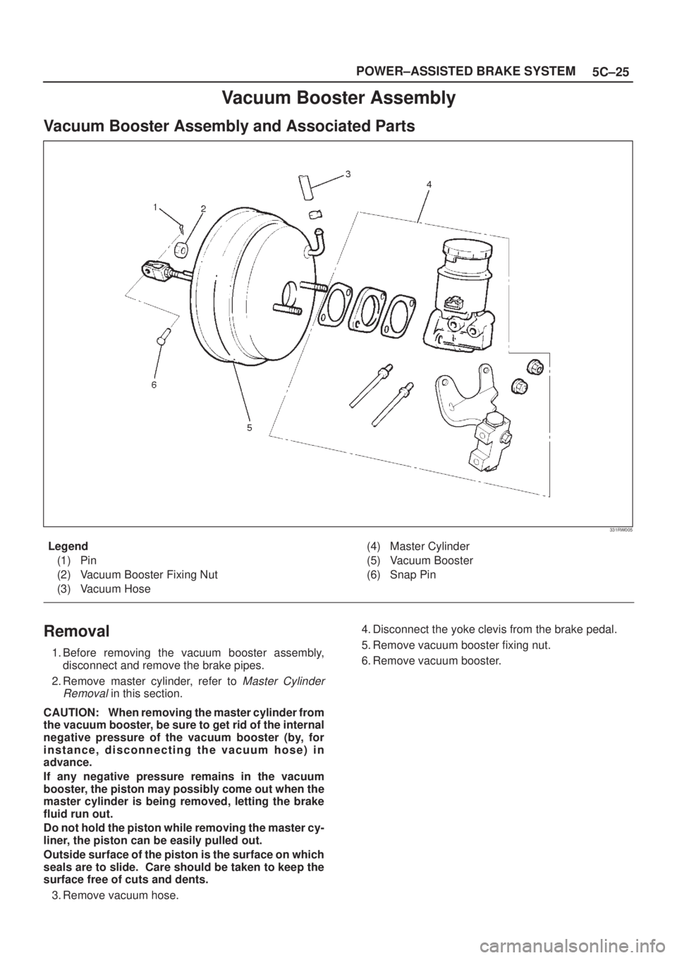
Vacuum Booster Assembly and Associated Parts
331RW005
Legend
(1) Pin
(2) Vacuum Booster Fixing Nut
(3) Vacuum Hose(4) Master Cylinder
(5) Vacuum Booster
(6) Snap Pin
Removal
1. Before removing the vacuum booster assembly,
disconnect and remove the brake pipes.
2. Remove master cylinder, refer to
Master Cylinder
Removal
in this section.
CAUTION: When removing the master cylinder from
the vacuum booster, be sure to get rid of the internal
negative pressure of the vacuum booster (by, for
instance, disconnecting the vacuum hose) in
advance.
If any negative pressure remains in the vacuum
booster, the piston may possibly come out when the
master cylinder is being removed, letting the brake
fluid run out.
Do not hold the piston while removing the master cy-
liner, the piston can be easily pulled out.
Outside surface of the piston is the surface on which
seals are to slide. Care should be taken to keep the
surface free of cuts and dents.
3. Remove vacuum hose.4. Disconnect the yoke clevis from the brake pedal.
5. Remove vacuum booster fixing nut.
6. Remove vacuum booster.
Page 713 of 2100
5C±33 POWER±ASSISTED BRAKE SYSTEM
Removal
NOTE: If a squealing noise occurs from the front brake
while driving, check the pad wear indicator plate. If the
indicator plate contacts the rotor, the disc pad assembly
should be replaced.
�Draw out two±thirds of the brake fluid from the
reservoir.
�Raise the vehicle and support it with suitable safety
stands.
1. Remove wheel and tire assembly, refer to
Wheels
and Tires System
in Section 3E.
2. Remove lock bolt (1).
302RW004
3. Rotate caliper assembly and support the caliper
assembly so that the brake hose is not stretched or
damaged.
4. Remove pad assembly with shim.
5. Remove Clip.
Installation
1. Install clip.
302RS005
2. Apply special grease (approximately 0.2 g) to both
contacting surfaces of the inner shims (2). Wipe off
extruded grease after installing. Install pad assembly
with shim.
302RW005
Legend
(2) Inner Shim
(3) Wear Indicator
(4) Inner Side
Page 714 of 2100
5C±34
POWER±ASSISTED BRAKE SYSTEM
302RW006
3. Carefyully use adjustable pliers to bottom the piston
into the caliper bore. Do not pull or twist the flexible
hose or damage will occur.
Install caliper assembly.
Set caliper assembly in place.
302RS008
4. Install lock bolt (5) and tighten the bolt to the specified
torque.
Torque: 74 N´m (54 lb ft)
302RW018
5. Install wheel and tire assembly, refer to Wheels and
Tires System
in Section 3E.
6. Pump the brake pedal several times to make sure that
the pedal is firm. Check the brake fluid level in the
reservoir after pumping the brakes.
Page 717 of 2100

5C±37 POWER±ASSISTED BRAKE SYSTEM
Removal
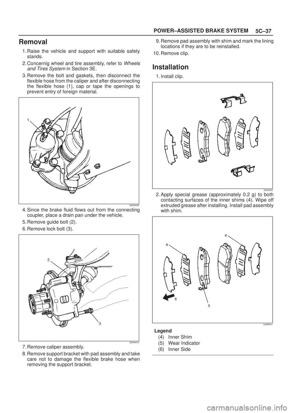
1. Raise the vehicle and support with suitable safety
stands.
2. Concernig wheel and tire assembly, refer to
Wheels
and Tires System
in Section 3E.
3. Remove the bolt and gaskets, then disconnect the
flexible hose from the caliper and after disconnecting
the flexible hose (1), cap or tape the openings to
prevent entry of foreign material.
302RW009
4. Since the brake fluid flows out from the connecting
coupler, place a drain pan under the vehicle.
5. Remove guide bolt (2).
6. Remove lock bolt (3).
302RW010
7. Remove caliper assembly.
8. Remove support bracket with pad assembly and take
care not to damage the flexible brake hose when
removing the support bracket.9. Remove pad assembly with shim and mark the lining
locations if they are to be reinstalled.
10. Remove clip.
Installation
1. Install clip.
302RS005
2. Apply special grease (approximately 0.2 g) to both
contacting surfaces of the inner shims (4). Wipe off
extruded grease after installing. Install pad assembly
with shim.
302RW011
Legend
(4) Inner Shim
(5) Wear Indicator
(6) Inner Side
Page 724 of 2100
5C±44
POWER±ASSISTED BRAKE SYSTEM
Removal
NOTE: If a squealing noise occurs from the rear brake
while driving, check the pad wear indicator plate. If the
indicator plate contacts the rotor, the disc pad assembly
should be replaced.
�Draw out two±thirds of the brake fluid from the
reservoir.
�Raise the vehicle and support it with suitable safety
stands.
1. Remove wheel and tire assembly, refer to
Wheels
and Tires System
in Section 3E.
2. Remove lock bolt (1)
306RW002
3. Rotate caliper assembly and support the caliper
assembly so that the brake hose is not stretched or
damaged.
4. Remove pad assembly with shim.
5. Remove clip.
Installation
1. Install clip (2).
306RW003
2. Apply special grease (approximately 0.2 g) to both
contacting surfaces of the inner shims. Wipe off
extruded grease after installing. Install pad assembly
with shim.
306RW004
Legend
(3) Inner Shim
(4) Wear Indicator
Page 725 of 2100
5C±45 POWER±ASSISTED BRAKE SYSTEM
306RW005
3. Carefyully use adjustable pliers to bottom the piston
into the caliper bore. Do not pull or twist the flex hose
or damage will occur.
302RS008
4. Install lock bolt (5) and tighten the bolt to the specified
torque.
Torque: 44 N´m (32 lb ft)
5. Install wheel and tire assembly, refer to
Wheels and
Tires System
in Section 3E.
6. Pump the brake pedal several times to make sure that
the pedal is firm. Check the brake fluid level in the
reservoir after pumping the brakes.
306RW006