Page 1952 of 2100
8H±2SECURITY AND LOCKS
Front Door Lock Assembly
Front Door Lock Assembly and Associated Parts
635R200008
Legend
(1) Door Mirror Cover
(2) Power Window Switch
(3) Door Trim Panel
(4) Inside Lock Bracket
(5) Inside Handle(6) Pull Box
(7) Pull Box Bracket
(8) Waterproof Sheet
(9) Door Lock Assembly
(10) Door Lock Cylinder
(11) Outside Handle
Removal
1. Disconnect the battery ground cable.
2. Remove the pull box.
�Remove the one fixing screw.
635R200004
Page 1953 of 2100
SECURITY AND LOCKS8H±3
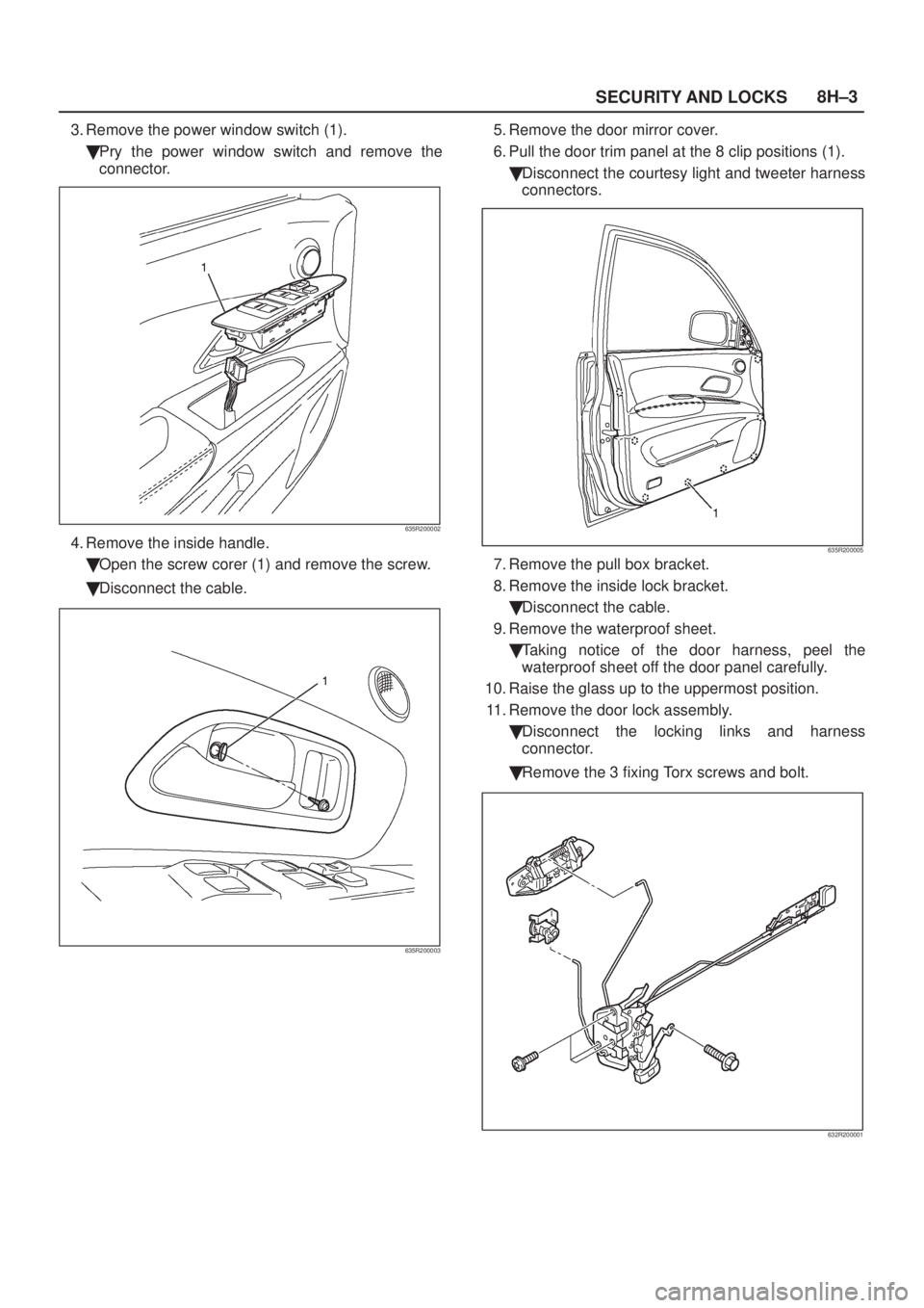
3. Remove the power window switch (1).
�Pry the power window switch and remove the
connector.
635R200002
4. Remove the inside handle.
�Open the screw corer (1) and remove the screw.
�Disconnect the cable.
635R200003
5. Remove the door mirror cover.
6. Pull the door trim panel at the 8 clip positions (1).
�Disconnect the courtesy light and tweeter harness
connectors.
635R200005
7. Remove the pull box bracket.
8. Remove the inside lock bracket.
�Disconnect the cable.
9. Remove the waterproof sheet.
�Taking notice of the door harness, peel the
waterproof sheet off the door panel carefully.
10. Raise the glass up to the uppermost position.
11. Remove the door lock assembly.
�Disconnect the locking links and harness
connector.
�Remove the 3 fixing Torx screws and bolt.
632R200001
Page 1955 of 2100
 Door Mirror Cover
(2) Power Window Switch
(3) Door Trim Panel
(4) Inside Lock Bracket
(5) I")
SECURITY AND LOCKS8H±5
Front Outside Handle
Front Outside Handle and Associated Parts
635R200008
Legend
(1) Door Mirror Cover
(2) Power Window Switch
(3) Door Trim Panel
(4) Inside Lock Bracket
(5) Inside Handle(6) Pull Box
(7) Pull Box Bracket
(8) Waterproof Sheet
(9) Door Lock Assembly
(10) Door Locking Cylinder
(11) Outside Handle
Removal
1. Disconnect the battery ground cable.
2. Remove the door trim panel.
�Refer to
Front Door Lock Assembly in this section.
3. Remove the waterproof sheet.
�Taking notice of the door harness, peel the
waterproof sheet off the door panel carefully.
4. Disconnect the locking links and remove the outside
handle.
5. Remove the fixing clip to remove the door lock
cylinder.
Installation
To install, follow the removal steps in the reverse order,
noting the following points:
1. Be sure to install the door lock cylinder at a specified
angle to the outside handle.
2. Check for smooth outside handle and lock cylinder
operation.
3. Tighten the outside handle fixing bolts to the specified
torque.
Torque 7 N´m (61 Ib in)
Page 1956 of 2100
8H±6SECURITY AND LOCKS
Rear Door Lock Assembly
Rear Door Lock Assembly and Associated Parts
655R200007
Legend
(1) Outside Handle
(2) Door Lock Assembly
(3) Pull Box Bracket
(4) Pull Box(5) Door Trim Panel
(6) Power Window Switch
(7) Inside Handle
(8) Inside Lock Bracket
(9) Waterproof Sheet
Removal
1. Disconnect the battery ground cable.
2. Remove the pull box.
�Remove the fixing screw.
655R200003
Page 1957 of 2100
SECURITY AND LOCKS8H±7
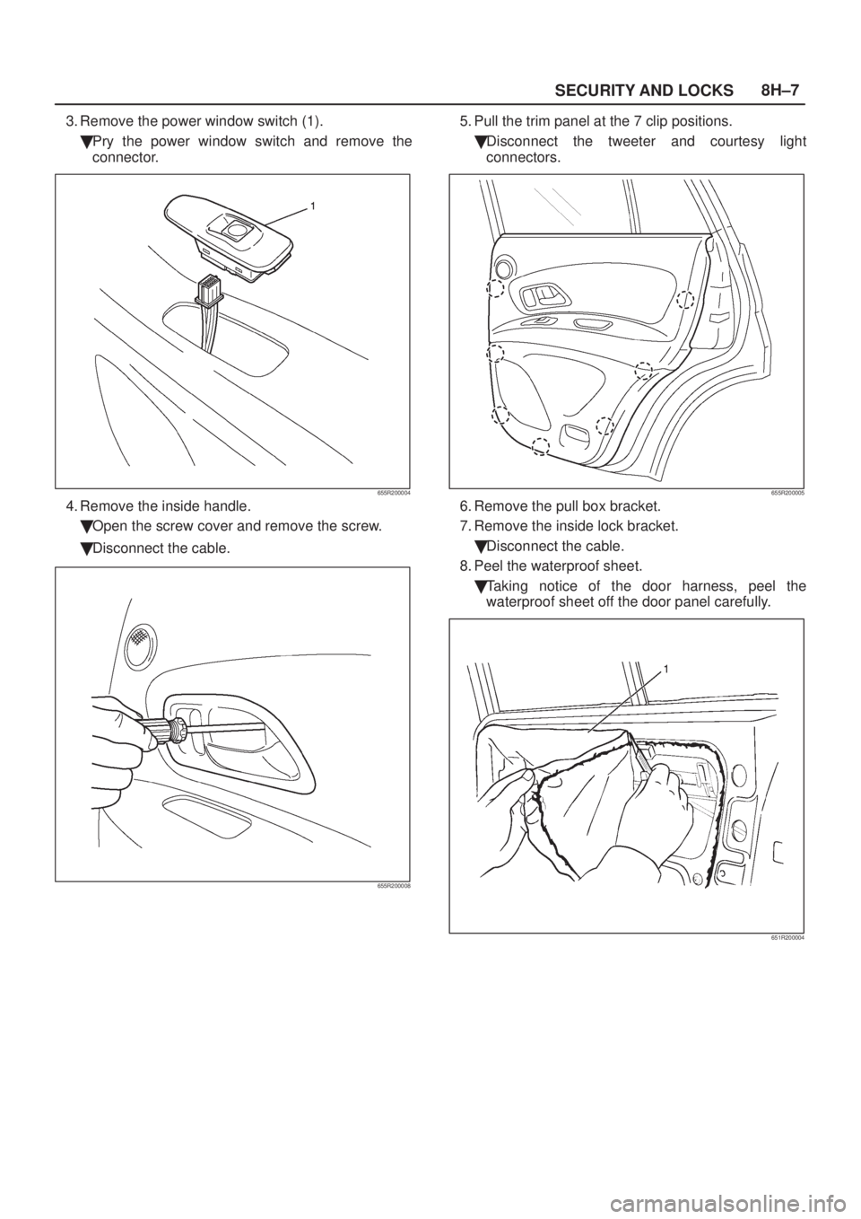
3. Remove the power window switch (1).
�Pry the power window switch and remove the
connector.
655R200004
4. Remove the inside handle.
�Open the screw cover and remove the screw.
�Disconnect the cable.
655R200008
5. Pull the trim panel at the 7 clip positions.
�Disconnect the tweeter and courtesy light
connectors.
655R200005
6. Remove the pull box bracket.
7. Remove the inside lock bracket.
�Disconnect the cable.
8. Peel the waterproof sheet.
�Taking notice of the door harness, peel the
waterproof sheet off the door panel carefully.
651R200004
Page 1959 of 2100
SECURITY AND LOCKS8H±9
Rear Outside Handle
Rear Outside Handle and Associated Parts
655R200007
Legend
(1) Outside Handle
(2) Door Lock Assembly
(3) Pull Box Bracket
(4) Pull Box(5) Door Trim Panel
(6) Power Window Switch
(7) Inside Handle
(8) Inside Lock Bracket
(9) Waterproof Sheet
Removal
1. Disconnect the battery ground cable.
2. Remove the door trim panel.
�Refer to
Rear Door Lock Assembly in this section.
3. Peel the waterproof sheet.
�Taking notice of the door harness, peel the
waterproof sheet off the door panel carefully.
4. Disconnect the locking link and remove fixing bolts to
remove the outside handle.
Installation
To install, follow the removal steps in the reverse order,
noting the following points.
1. Check that the outside handle operates smoothly.
2. Tighten the outside handle fixing bolts to the specified
torque.
Torque 7 N´m (61 Ib in)
Page 1970 of 2100

SUN ROOF/CONVERTIBLE TOP8I±1
AXIOM
BODY AND ACCESSORIES
SUNROOF/CONVERTIBLE TOP
CONTENTS
Service Precaution 8I±1. . . . . . . . . . . . . . . . . . . . . .
Sunroof Glass 8I±2. . . . . . . . . . . . . . . . . . . . . . . . . .
Sunroof Glass and Associated Parts 8I±2. . . . .
Removal 8I±2. . . . . . . . . . . . . . . . . . . . . . . . . . . . .
Installation 8I±3. . . . . . . . . . . . . . . . . . . . . . . . . . . .
Sunroof Deflector 8I±3. . . . . . . . . . . . . . . . . . . . . . .
Removal 8I±3. . . . . . . . . . . . . . . . . . . . . . . . . . . . .
Installation 8I±3. . . . . . . . . . . . . . . . . . . . . . . . . . . .
Sunshade 8I±4. . . . . . . . . . . . . . . . . . . . . . . . . . . . . .
Disassembled View 8I±4. . . . . . . . . . . . . . . . . . . .
Removal 8I±4. . . . . . . . . . . . . . . . . . . . . . . . . . . . .
Installation 8I±5. . . . . . . . . . . . . . . . . . . . . . . . . . . .
Sunroof Frame Complete Assembly 8I±6. . . . . . . Sunroof Frame Complete Assembly and
Associated Parts 8I±6. . . . . . . . . . . . . . . . . . . . . .
Removal 8I±6. . . . . . . . . . . . . . . . . . . . . . . . . . . . .
Installation 8I±7. . . . . . . . . . . . . . . . . . . . . . . . . . . .
Sunroof Switch 8I±7. . . . . . . . . . . . . . . . . . . . . . . . . .
Removal 8I±7. . . . . . . . . . . . . . . . . . . . . . . . . . . . .
Installation 8I±7. . . . . . . . . . . . . . . . . . . . . . . . . . . .
Sunroof Control Unit 8I±8. . . . . . . . . . . . . . . . . . . . .
Removal 8I±8. . . . . . . . . . . . . . . . . . . . . . . . . . . . .
Installation 8I±8. . . . . . . . . . . . . . . . . . . . . . . . . . . .
Sunroof Motor 8I±8. . . . . . . . . . . . . . . . . . . . . . . . . .
Removal 8I±8. . . . . . . . . . . . . . . . . . . . . . . . . . . . .
Installation 8I±8. . . . . . . . . . . . . . . . . . . . . . . . . . . .
Main Data and Specifications 8I±9. . . . . . . . . . . . .
Service Precaution
WARNING: THIS VEHICLE HAS A SUPPLEMENTAL
RESTRAINT SYSTEM (SRS). REFER TO THE SRS
COMPONENT AND WIRING LOCATION VIEW IN
ORDER TO DETERMINE WHETHER YOU ARE
PERFORMING SERVICE ON OR NEAR THE SRS
COMPONENTS OR THE SRS WIRING. WHEN YOU
ARE PERFORMING SERVICE ON OR NEAR THE SRS
COMPONENTS OR THE SRS WIRING, REFER TO
THE SRS SERVICE INFORMATION. FAILURE TO
FOLLOW WARNINGS COULD RESULT IN POSSIBLE
AIR BAG DEPLOYMENT, PERSONAL INJURY, OR
OTHERWISE UNNEEDED SRS SYSTEM REPAIRS.CAUTION: Always use the correct fastener in the
proper location. When you replace a fastener, use
ONLY the exact part number for that application.
ISUZU will call out those fasteners that require a
replacement after removal. ISUZU will also call out
the fasteners that require thread lockers or thread
sealant. UNLESS OTHERWISE SPECIFIED, do not
use supplemental coatings (Paints, greases, or other
corrosion inhibitors) on threaded fasteners or
fastener joint interfaces. Generally, such coatings
adversely affect the fastener torque and the joint
clamping force, and may damage the fastener. When
you install fasteners, use the correct tightening
sequence and specifications. Following these
instructions can help you avoid damage to parts and
systems.
Page 1971 of 2100
8I±2SUN ROOF/CONVERTIBLE TOP
Sunroof Glass
Sunroof Glass and Associated Parts
665R200003
Legend
(1) Sunroof Weatherstrip
(2) Sunroof Glass
Removal
1. Tilt the sunroof and open the sunshade.
2. Disconnect the battery ground cable.
3. Pull out the front of sight shield (2).
4. Remove four sunroof glass fixing Torx screws (3) to
remove the sunroof glass (1).
665R200004
 Door Mirror Cover
(2) Power Window Switch
(3) Door Trim Panel
(4) Inside Lock Brack")
 Outside Handle
(2) Door Lock Assembly
(3) Pull Box Bracket
(4) Pull Box(5) Door Trim")
 Outside Handle
(2) Door Lock Assembly
(3) Pull Box Bracket
(4) Pull Box(5) Door Trim Panel
(6")
 Sunroof Weatherstrip
(2) Sunroof Glass
Removal
1. Tilt the sunroof and open the sunshade.
2. Discon")