Page 357 of 2100

4A2±18DIFFERNTIAL (REAR)
14. Set the dial indicator to ª0º. Place it on the mounting
post of the gauging arbor with the contact button
touching the indicator pad.
Force the dial indicator downward until the needle has
made a half turn clockwise. Tighten down the dial
indicator in this position.
425RS020
Legend
(1) Dial Indicator
(2) Ganging Arbor
(3) Plunger
(4) Gaug Plate
15. Position the plunger on the gauge plate. Move the
gauging arbor slowly back and forth and locate the
position at which the dial indicator shows the greatest
defection. At this point, once again set the dial
indicator to ª0º.
Repeat the procedure to verify the ª0º setting.
425RS021
16. After the ZERO setting is obtained, rotate the gauging
arbor until the dial indicator rod does not touch the
gauging plate.
Record the number the dial indicator needle points to.
425RS022
Legend
(1) Example=Dial indicator reading of 0.085
17. Record the pinion depth code on the head of the drive
pinion.
The number indicates a necessary change in the
pinion mounting distance. A plus number indicates
the need for a greater mounting distance (which can
be achieved by decreasing the shim thickness). A
minus number indicates the need for a smaller
mounting distance (which can be achieved by
increasing the shim thickness). If examination
reveals pinion depth code ª0º, the pinion is ªnominalº.
425RS023
Page 839 of 2100

6A±29
ENGINE MECHANICAL (6VE1 3.5L)
3. Align the alignment mark (white line) on the timing
belt (1) with alignment mark on the RH bank
camshaft drive pulley (2) (on the left side as
viewed from the front of the vehicle) and put the
timing belt on the camshaft drive pulley.
Secure the belt with a double clip or equivalent
clip.
014RW00004
Legend
(1) Alignment Mark on Timing Belt (White line).
(2) Alignment Mark on Camshaft Drive Pulley.
(3) Alignment Mark on Cylinder Head Cover RH.
4. Align the alignment mark on the LH bank
camshaft drive pulley (2) to the alignment mark of
the cylinder head cover LH (3).
The camshaft pulley is not 1:1 with the camshafts.
It is necessary to rotate the camshaft pulley until
the camshaft lobes are in the position as shown
in the diagram on page 6A±34.
The camshaft pulley alignment mark should also
align with alignment mark on the cylinder head
cover.
It may require up to four revolutions of the cam-
shaft pulley to achieve alignment of all marks.
5. Align the alignment mark (white line) on the timing
belt (1) with the alignment mark on the LH bank
camshaft drive pulley (2).
When aligning the timing marks, use a wrench to
turn the camshaft drive pulley, then set the timing
mark between timing belt and camshaft drive
pulley and put the timing belt on the camshaft
drive pulley.
Secure the belt with a double clip or equivalent
clip.NOTE: It is recommended for easy installation that the
belt be secured with a double clip or equivalent clips after
it is installed to each pulley.
014RW00005
Legend
(1) Alignment Mark on Timing Belt (White line).
(2) Alignment Mark on Camshaft Drive Pulley.
(3) Alignment Mark on Cylinder Head Cover LH.
6. Install crankshaft pulley temporarily and tighten
center bolt by hand (do not use a wrench).
Turn the crankshaft pulley clockwise to give some
belt slack between the crankshaft timing pulley
and the RH bank camshaft drive pulley.
2. Install pusher and tighten bolt to the specified torque.
Torque : 25 N´m (2.5 kg´m/18 lb ft)
1. Install the pusher while pushing the tension pulley
to the belt.
2. Pull out pin from the pusher.
NOTE: When reusing the pusher, press the pusher with
approximately 100Kg to retract the rod, and insert a pin
(1.4 mm (0.055 in) piano wire).
Page 873 of 2100

6A±63
ENGINE MECHANICAL (6VE1 3.5L)
3. Measure the camshaft thrust clearance with a dial
indicator. Replace the camshaft and/or the
cylinder head if the camshaft thrust clearance
exceeds the specified limit.
Camshaft thrust Clearance
Standard : 0.03 mm±0.08 mm
(0.0012 in.±0.0031 in.)
Limit : 0.12 mm (0.0047 mm)
014RW035
Reassembly
1. Install camshaft drive gear assembly and tighten
three bolts to specified torque.
Torque: 10 N´m (89 lb in)
2. Install the spring ; camshaft gear(1) into the camshaft
assembly.
Ensure the clearance is between the right side of the
spring; camshaft gear (1) and the dowel pin (2).
014R100017
3. Align the dowel pin on the sub gear to the clearance of
the spring ; camshaft gear made in step 2 and install
the sub gear (3).
4. Install the wave washer (2). Use snap ring pliers to
install the snap ring (1).
014R100018
5. Tighten sub gear setting bolt.
a. Use J±42686 gear spring lever to pre-load the sub
gear. Turn the sub gear in a clockwise direction
until the M5 bolt hole aligns with the hole in the
camshaft driven gear.
b. Install the M5 bolt and tighten to a suitable torque to
prevent the sub gear from moving.
014RW041
6. Align the timing mark on the retainer and dowel pin of
the camshaft drive gear.
7. Install camshaft assembly and camshaft brackets,
tighten twenty bolts on one side bank to the specified
torque.
Page 955 of 2100
6D3±13
STARTING AND CHARGING SYSTEM (6VE1 3.5L)
2. Check continuity between the lead wire of terminal C
and brush.
Replace the yoke assembly, if there is no continuity.
065RY00066
Overrunning Clutch
1. Visual check for excessive wear or damage.
2. Test the pinion rotation, it must rotate smoothly when
rotated clockwise and it shouldn't rotate when turned
counterclockwise.
065RY00067
Bearing
1. Inspect excessive wear or damage.
Replace the bearing if an abnormal noise is heard
under normal operating condition.
065RY00068
Reassembly
To install, follow the removal steps in the reverse order,
noting the following points:
Grease application places
�Bearing in rear cover
�Gears in reduction gear
�Sliding portion of pinion
Page 956 of 2100
6D3±14
STARTING AND CHARGING SYSTEM (6VE1 3.5L)
Main Data and Specifications
General Specifications
ModelSpecification
Rating
Voltage12 V
Output1.4 Kw
Time30 sec
Number of teeth of pinion 9
Rotating direction(as viewed from pinion)Clockwise
Weight(approx.)37 N
No±load characteristics
Condition: Voltage 11.5V
Current 90A or less
Speed 3000rpm or more
Load characteristics
Condition: Voltage/Torque 8.5V/13.2 N´m (113 lb in)
Current Maximum 350A
Speed 1000rpm or more
Locking characteristics
Condition: Voltage 2.4V
Current Maximum 500A
Torque11.8N´m or more
Page 967 of 2100
6D3±25
STARTING AND CHARGING SYSTEM (6VE1 3.5L)
Main Data and Specifications
General Specifications
Battery voltageV12
Rated outputA90
Direction of rotation
(as viewed from pulley side)Clockwise
Rated rotation speedrpm 5000
Maximum speedrpm18000
Page 1462 of 2100

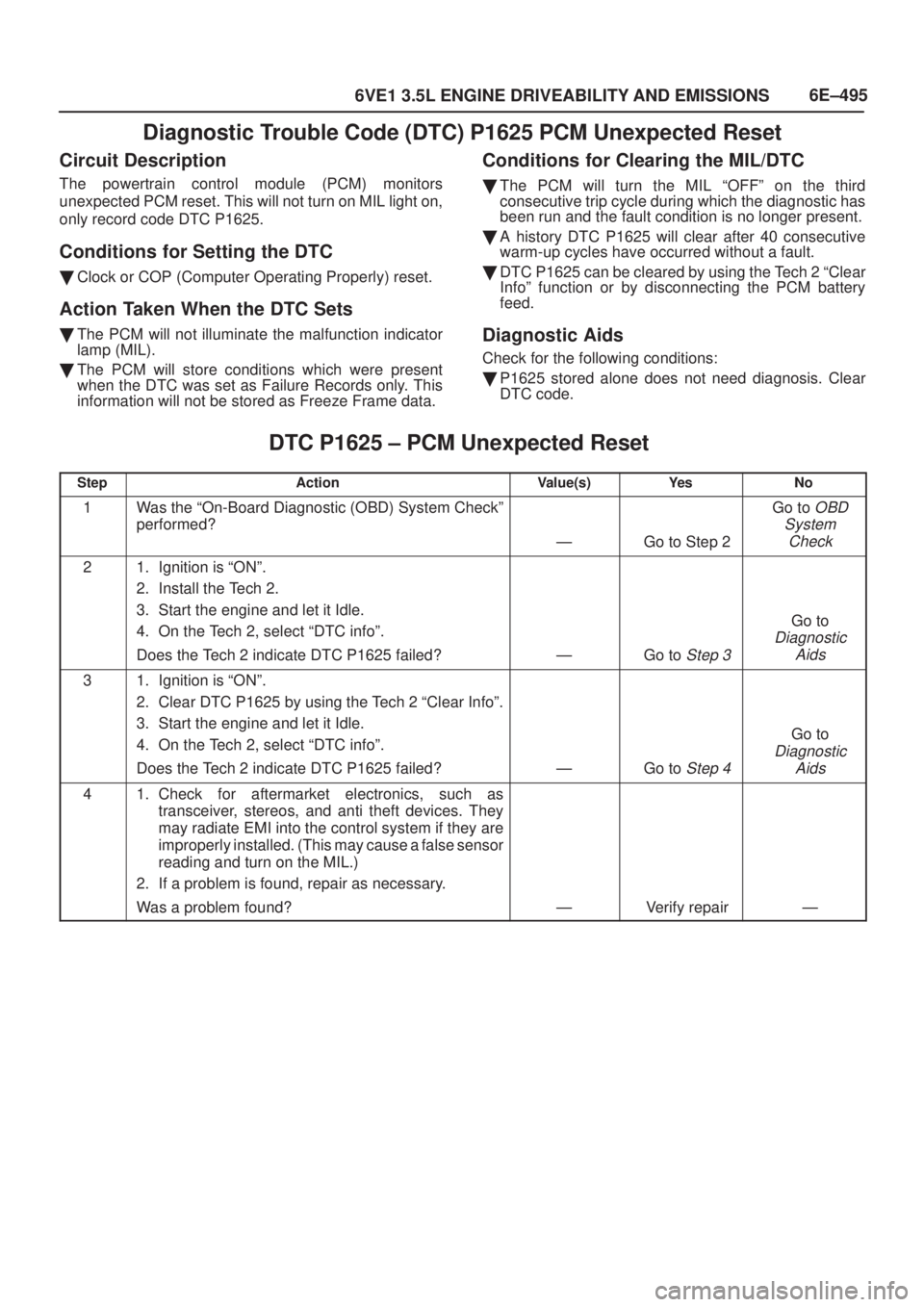
6E±495
6VE1 3.5L ENGINE DRIVEABILITY AND EMISSIONS
Diagnostic Trouble Code (DTC) P1625 PCM Unexpected Reset
Circuit Description
The powertrain control module (PCM) monitors
unexpected PCM reset. This will not turn on MIL light on,
only record code DTC P1625.
Conditions for Setting the DTC
�Clock or COP (Computer Operating Properly) reset.
Action Taken When the DTC Sets
�The PCM will not illuminate the malfunction indicator
lamp (MIL).
�The PCM will store conditions which were present
when the DTC was set as Failure Records only. This
information will not be stored as Freeze Frame data.
Conditions for Clearing the MIL/DTC
�The PCM will turn the MIL ªOFFº on the third
consecutive trip cycle during which the diagnostic has
been run and the fault condition is no longer present.
�A history DTC P1625 will clear after 40 consecutive
warm-up cycles have occurred without a fault.
�DTC P1625 can be cleared by using the Tech 2 ªClear
Infoº function or by disconnecting the PCM battery
feed.
Diagnostic Aids
Check for the following conditions:
�P1625 stored alone does not need diagnosis. Clear
DTC code.
DTC P1625 ± PCM Unexpected Reset�
StepActionValue(s)Ye sNo
1Was the ªOn-Board Diagnostic (OBD) System Checkº
performed?
ÐGo to Step 2
Go to OBD
System
Check
21. Ignition is ªONº.
2. Install the Tech 2.
3. Start the engine and let it Idle.
4. On the Tech 2, select ªDTC infoº.
Does the Tech 2 indicate DTC P1625 failed?
ÐGo to Step 3
Go to
Diagnostic
Aids
31. Ignition is ªONº.
2. Clear DTC P1625 by using the Tech 2 ªClear Infoº.
3. Start the engine and let it Idle.
4. On the Tech 2, select ªDTC infoº.
Does the Tech 2 indicate DTC P1625 failed?
ÐGo to Step 4
Go to
Diagnostic
Aids
41. Check for aftermarket electronics, such as
transceiver, stereos, and anti theft devices. They
may radiate EMI into the control system if they are
improperly installed. (This may cause a false sensor
reading and turn on the MIL.)
2. If a problem is found, repair as necessary.
Was a problem found?
ÐVerify repairÐ
Page 1663 of 2100

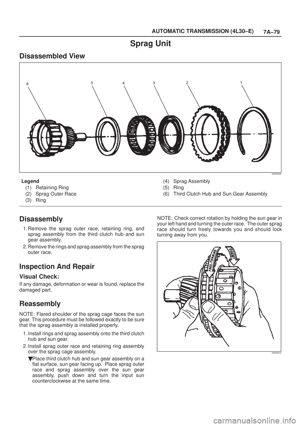
7A±79 AUTOMATIC TRANSMISSION (4L30±E)
Sprag Unit
Disassembled View
248RS009
Legend
(1) Retaining Ring
(2) Sprag Outer Race
(3) Ring(4) Sprag Assembly
(5) Ring
(6) Third Clutch Hub and Sun Gear Assembly
Disassembly
1. Remove the sprag outer race, retaining ring, and
sprag assembly from the third clutch hub and sun
gear assembly.
2. Remove the rings and sprag assembly from the sprag
outer race.
Inspection And Repair
Visual Check:
If any damage, deformation or wear is found, replace the
damaged part.
Reassembly
NOTE: Flared shoulder of the sprag cage faces the sun
gear. This procedure must be followed exactly to be sure
that the sprag assembly is installed properly.
1. Install rings and sprag assembly onto the third clutch
hub and sun gear.
2. Install sprag outer race and retaining ring assembly
over the sprag cage assembly.
�Place third clutch hub and sun gear assembly on a
flat surface, sun gear facing up. Place sprag outer
race and sprag assembly over the sun gear
assembly, push down and turn the input sun
counterclockwise at the same time. NOTE: Check correct rotation by holding the sun gear in
your left hand and turning the outer race. The outer sprag
race should turn freely towards you and should lock
turning away from you.
248RS010