Page 1852 of 2100
8D±17
WIRING SYSTEM
Audio, Clock, Cigarette Lighter and ACC Socket
D08R200048
Page 1872 of 2100
8E±6METER AND GAUGE
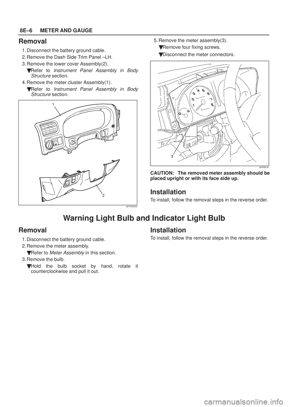
Removal
1. Disconnect the battery ground cable.
2. Remove the Dash Side Trim Panel ±LH.
3. Remove the lower cover Assembly(2).
�Refer to
Instrument Panel Assembly in Body
Structure
section.
4. Remove the meter cluster Assembly(1).
�Refer to
Instrument Panel Assembly in Body
Structure
section.
821R200020
5. Remove the meter assembly(3).
�Remove four fixing screws.
�Disconnect the meter connectors.
825RW197
CAUTION: The removed meter assembly should be
placed upright or with its face side up.
Installation
To install, follow the removal steps in the reverse order.
Warning Light Bulb and Indicator Light Bulb
Removal
1. Disconnect the battery ground cable.
2. Remove the meter assembly.
�Refer to
Meter Assembly in this section.
3. Remove the bulb.
�Hold the bulb socket by hand, rotate it
counterclockwise and pull it out.
Installation
To install, follow the removal steps in the reverse order.
Page 1875 of 2100
METER AND GAUGE8E±9
Vehicle Speed Sensor
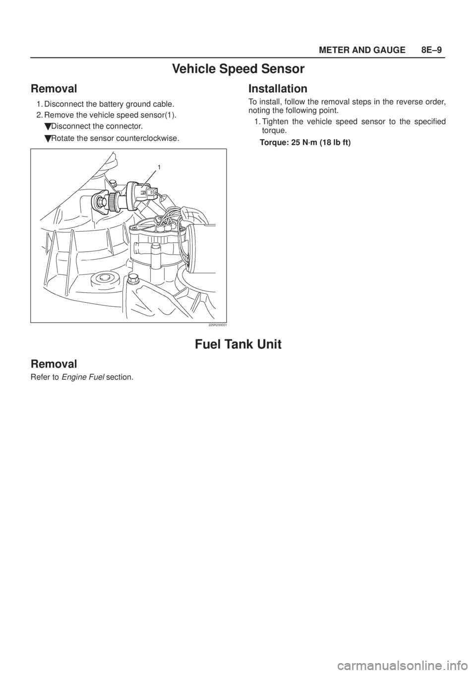
Removal
1. Disconnect the battery ground cable.
2. Remove the vehicle speed sensor(1).
�Disconnect the connector.
�Rotate the sensor counterclockwise.
225R200001
Installation
To install, follow the removal steps in the reverse order,
noting the following point.
1. Tighten the vehicle speed sensor to the specified
torque.
Torque: 25 N´m (18 lb ft)
Fuel Tank Unit
Removal
Refer to Engine Fuel section.
Page 1926 of 2100
8F±50BODY STRUCTURE
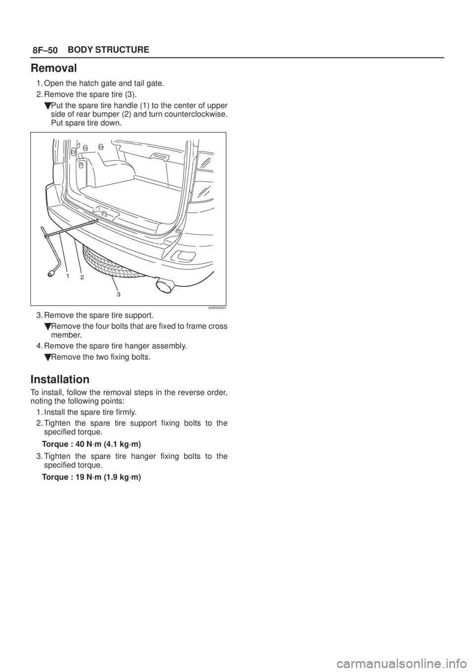
Removal
1. Open the hatch gate and tail gate.
2. Remove the spare tire (3).
�Put the spare tire handle (1) to the center of upper
side of rear bumper (2) and turn counterclockwise.
Put spare tire down.
530R200001
3. Remove the spare tire support.
�Remove the four bolts that are fixed to frame cross
member.
4. Remove the spare tire hanger assembly.
�Remove the two fixing bolts.
Installation
To install, follow the removal steps in the reverse order,
noting the following points:
1. Install the spare tire firmly.
2. Tighten the spare tire support fixing bolts to the
specified torque.
Torque : 40 N´m (4.1 kg´m)
3. Tighten the spare tire hanger fixing bolts to the
specified torque.
Torque : 19 N´m (1.9 kg´m)
Page 1947 of 2100
SEATS8G±9
Rear Seat Back Assembly and Associated Parts
755R200005
Legend
(1) Headrest
(2) Seat Back Assembly
(3) Guide Holder
(4) Release Knob(5) Seat Lock Cover
(6) Seat Lock Striker
(7) Side Hinge
(8) Body Floor Panel
(9) Center Hinge
Removal
1. Pull the release knob and pull the seat back assembly
forward.
2. Remove the seat lock covers.
�Remove the three screws from each side.
3. Remove the luggage floor carpets.
�Pull the nine carpet fixing clips from the backside of
the seat back assembly.4. Remove the seat back assembly.
�Remove the four fixing bolts at each seat back.
5. Remove the headrests.
6. Remove the release knobs.
�Turn the knob counterclockwise to remove it.
7. Remove the trim covers.
8. Remove the guide holders.
9. Remove the side hinges.
�Remove the one fixing nut at each side hinge.
Page 2046 of 2100

SUPPLEMENTAL RESTRAINT SYSTEM 9J±32
SRS Coil Assembly
Service Precaution
WARNING: S A F E T Y P R ECAUTIONS MUST BE
FOLLOWED WHEN HANDLING A DEPLOYED AIR
BAG ASSEMBLY. AFTER DEPLOYMENT, THE AIR
BAG ASSEMBLY SURFACE MAY CONTAIN A SMALL
AMOUNT OF SODIUM HYDROXIDE, A BY±PRODUCT
OF THE DEPLOYMENT REACTION, THAT IS
IRRITATING TO THE SKIN AND EYES. MOST OF THE
POWDER ON THE AIR BAG ASSEMBLY IS
HARMLESS. AS A PRECAUTION, WEAR GLOVES
AND SAFETY GLASSES WHEN HANDLING A
DEPLOYED AIR BAG ASSEMBLY, AND WASH YOUR
HANDS WITH MILD SOAP AND WATER
AFTERWARDS.
WARNING: W H E N C A R RY I N G A L I V E A I R B A G
ASSEMBLY, MAKE SURE THE BAG AND TRIM
COVER ARE POINTED AWAY FROM YOU. NEVER
CARRY AIR BAG ASSEMBLY BY THE WIRES OR
CONNECTOR ON THE UNDERSIDE OF MODULE. IN
THE CASE OF AN ACCIDENTAL DEPLOYMENT, THE
BAG WILL THEN DEPLOY WITH MINIMAL CHANCE
OF INJURY. WHEN PLACING A LIVE AIR BAG
ASSEMBLY ON A BENCH OR OTHER SURFACE,
ALWAYS FACE BAG AND TRIM COVER UP, AWAY
FROM THE SURFACE. NEVER REST A STEERING
COLUMN ASSEMBLY ON THE STEERING WHEEL
WITH THE AIR BAG ASSEMBLY FACE DOWN AND
COLUMN VERTICAL. THIS IS NECESSARY SO THAT
A FREE SPACE IS PROVIDED TO ALLOW THE AIR
BAG ASSEMBLY TO EXPAND IN THE UNLIKELY
EVENT OF ACCIDENTAL DEPLOYMENT.
OTHERWISE, PERSONAL INJURY COULD RESULT.
NOTE: In the event deployment has occurred, inspect
coil assembly wire for any signs of scorching, melting or
any other damage due to excessive heat. If the coil has
been damaged, replace it.
Removal
1. Disable the SRS. (Refer to ªDisabling the SRSº in this
section.)
2. Remove the air bag assembly (6) from steering wheel
(7) by removing two bolts (8). Lift air bag assembly out
of steering wheel.
3. Disconnect the 2±pin yellow connector (2) and
remove air bag assembly.
4. Disconnect horn lead connector (1).
5. Remove the steering wheel attachment nut (5).
6. Move the tires to the straight ahead position before
removing the steering wheel and remove wheel with
J±29752.
7. Apply a setting mark (4) across the steering wheel
and shaft so parts can be reassembled in their original
position.
8. Feed wiring though the wheel and remove wheel.
9. Remove the steering lower cover.
10. Remove the driver knee bolster assembly.11. Remove the steering column cover (3).
12. Disconnect the wiring harness connectors (10)
located at the base of steering column.
CAUTION: Never apply force to the steering wheel
in the direction of the shaft by using a hammer or
other impact tools in an attempt to remove the
steering wheel. The steering shaft is designed as an
energy absorbing unit.
13. Remove the combination switch assembly with SRS
coil (9).
NOTE: S R S c o i l i s a p a r t o f combination switch
assembly, which cannot be replaced separately.
Therefore, be sure not to remove the SRS coil from the
combination switch assembly.
825RX008
Installation
1. Install the combination switch assembly with SRS
coil (9).
2. Connect the wiring harness connectors (10) located
at the base of steering column.
3. Turn the SRS coil clockwise to full, return about 3
turns and align the neutral mark.
NOTE: Whenever installing the new combination switch
with SRS coil, be sure to tear off the lock pin for aligning
the neutral position before it is installed to the base of
steering column.
CAUTION: When turning the SRS coil clockwise to
full, stop turning if resistance is felt. Forced further
turning may damage the cable in the SRS coil.
4. Install the steering column cover (3).
CAUTION: When installing the steering column
cover, be sure to through each harness as illustrated
so that the harnesses starter switch, combination
switch and SRS coil may not catch wiring.
5. Install the driver knee bolster assembly.
6. Install the steering lower cover.
Page 2049 of 2100
 and align
the setting marks on the universal joint and steering
shaft made during removal.
2. Tighten the")
SUPPLEMENTAL RESTRAINT SYSTEM9J±35
Installation
1. Install the steering column assembly (13) and align
the setting marks on the universal joint and steering
shaft made during removal.
2. Tighten the steering column fixing bolts (dash panel
side) to the specified torque.
Torque: 20 N´m (14 lb ft)
3. Tighten the steering column fixing nuts (Cross beam)
to the specified torque.
Torque: 20 N´m (14 lb ft)
4. Tighten the universal joint to the specified torque.
Torque: 31 N´m (23 lb ft)
5. Install steering lock cylinder assembly (11).
6. Connect shift lock cable (For A/T)
7. Install cushion rubber.
8. Install snap ring.
9. Install the combination switch assembly with SRS coil
(9).
10. Connect the wiring harness connector (10) located on
the base of steering column.
11. Turn the SRS coil clockwise to full, return about 3
turns and align the neutral mark.
CAUTION: When turning the SRS coil clockwise to
full, stop turning if resistance is felt. Further forced
turning may damage the cable in the SRS coil.
12. Install steering column cover (1).
CAUTION: When installing the steering column
cover, be sure to wire (through each harness) as
illustrated so that the harnesses starter switch,
combination switch and SRS coil may not catch
wiring.
13. Install the steering wheel (2) and align the setting
marks (6).
14. Tighten the steering wheel fixing nut (3) to the
specified torque.
Torque: 34 N´m (25 lb ft)
15. Connect horn lead (8).
16. Connect air Bag wiring harness connector (7).
NOTE: Pass the lead wire through the tabs on the plastic
cover (wire protector) of air bag to prevent lead wire from
being pinched.17. Install air bag into steering wheel and tighten bolts (5)
to specified sequence as shown in figure.
Torque: 8.8 N´m (78 lb in)
CAUTION: Never use the air bag assembly from
another vehicle and difference model year air bag
assembly.
The air bag assembly has identification colors on the
bar code label as follows.
Light blue color for driver air bag assembly.
Light blue color for passenger air bag assembly.
Use only the air bag assembly for ªUPº.
431R200004
18. Enable the SRS (Refer to ªEnabling The SRSº in this
section.)

 Headrest
(2) Seat Back Assembly
(3) Guide Holder
(4) Release Knob(5) Seat Lock Cover
(6) Seat Lock Striker
(7) Side Hinge")