Page 1636 of 2100

Transmission Oil Temperature Sensor (Main Case)
Removal
1. Raise the vehicle and support it on jack stands.
2. Disconnect battery ground cable.
3. Drain fluid.")
7A±52
AUTOMATIC TRANSMISSION (4L30±E)
Transmission Oil Temperature Sensor (Main Case)
Removal
1. Raise the vehicle and support it on jack stands.
2. Disconnect battery ground cable.
3. Drain fluid.
4. Remove sixteen 10 mm main case oil pan fixing
screws, main case oil pan, and gasket.
5. Disconnect wiring harness from shift solenoids, band
apply solenoid, and 7 way connector of main case.
Pull only on connectors, not on wiring harness.
6. Remove wiring harness assembly with transmission
oil temperature sensor.
244RY001
Installation
1. Install wiring harness assembly with transmission oil
temperature sensor to band apply solenoid, shift
solenoids, and 7 way connector of main case.
2. Install oil pan gasket, oil pan, and sixteen 10 mm
fixing screws. Tighten the screws to the specified
torque.
Torque: 11 Nwm (96 lb in)
3. Fill transmission through the overfill screw hole of oil
pan, using ATF DEXRON)±III.
Refer to
Changing Transmission Fluid in this section.
4. Connect battery ground cable.
Page 1637 of 2100

Front Oil Seal (Converter Housing)
Removal
1. Remove transmission assembly from the vehicle.
Refer to
Transmission Assembly in this section.
2. Remove torque c")
7A±53 AUTOMATIC TRANSMISSION (4L30±E)
Front Oil Seal (Converter Housing)
Removal
1. Remove transmission assembly from the vehicle.
Refer to
Transmission Assembly in this section.
2. Remove torque converter from converter housing.
3. Remove three screws and oil seal ring from converter
housing.
241RW008
Installation
1. Apply clean ATF to the new oil seal ring lip.
�Install oil seal ring to converter housing. Tighten the
screws to the specified torque.
Torque: 3 Nwm (26 lb in)
2. Install torque converter to converter housing.
3. Install transmission assembly to the vehicle. Refer to
Transmission Assembly in this section.
Rear Oil Seal (Extension Assembly)
Removal
1. Remove transfer case assembly (4y4) or extension
assembly (4y2) from the vehicle. Refer to
Transfer
Case in Drive Line/Axle section (4
y4).
2. Remove rear oil seal from transmission extension
assembly.
241RW005
Installation
1. Use J±36797 extension assembly oil seal installer,
and install the rear oil seal to the transmission
extension assembly.
2. Install the transfer case assembly (4y4) or extension
assembly (4y2) to the vehicle. Refer to
Transfer Case
in Drive Line/Axle section (4
y4).
Page 1638 of 2100

Transmission (4L30±E)
Disassembly
NOTE: During the disassembly and reassembly, perform
the following:
�Wash each part thoroughly, and blow air through each
oil")
7A±54
AUTOMATIC TRANSMISSION (4L30±E)
Transmission (4L30±E)
Disassembly
NOTE: During the disassembly and reassembly, perform
the following:
�Wash each part thoroughly, and blow air through each
oil passage and groove to eliminate blockage.
�Seal rings, roll pins, and gaskets should be replaced.
�When assembling the components, apply
DEXRON)±III Automatic Transmission Fluid (ATF)
to each seal, rotating part, and sliding part.
�Do not dip part facings, such as clutch or brake drive
plates, in cleaner when washing it.
Also, always coat parts with new ATF two or three
times after cleaning with solvent.
1. Remove torque converter (1).
�Drain fluid from torque converter.
�Attach J±8763±02 holding fixture to the
transmission and set it on J±3289±20 holding
fixture base.
NOTE: Do not overtighten the tool, as case damage may
result.
420RW021
2. Remove O±ring (2) from turbine shaft.
3. Remove two 10mm mode switch screws, selector
lever nut, cover, and mode switch (3).
4. Remove twelve 10mm adapter case oil pan (4) fixing
screws, adapter oil pan, and gasket.
5. Disconnect electrical wiring connections (5) from
solenoids and 4 way connector of adapter case. Pull
on connectors only, not on wiring harness.
6. Remove seven 13mm adapter case valve body (6)
fixing screws, adapter case valve body assembly,
transfer plate, and two gaskets.
�Remove wiring harness and 4 way connector.
7. Remove sixteen 10mm main case oil pan (7) fixing
screws, main oil pan, magnet, and gasket.
8. Remove three 13mm oil filter (8) fixing screws and oil
filter.9. Remove two 13mm manual detent (9) fixing screws,
roller and spring, and manual detent.
10. Disconnect wiring harness assembly (10) from band
apply solenoid, shift solenoids, and main case 7 way
connector.
Pull on connectors only, not on wiring harness.
11. Remove four 13mm servo cover (11) fixing screws,
servo cover, and gasket.
12. Remove seven 13mm valve body screws from main
case.
�Remove wiring harness assembly (5) from the
adapter case side.
�Remove main valve body assembly (12) with
manual valve link and transfer plate. Note the
position of the link (long end into valve, short end
into range selector lever).
�Remove 7 way connector.
�Remove gasket transfer plate from main case.
Page 1639 of 2100
7A±55 AUTOMATIC TRANSMISSION (4L30±E)
13. Remove two check balls (13) from main case.
240RY001
14. Turn transmission to vertical position to drain fluid.
Return back to horizontal position when drained.
�Install J±23075 servo piston spring compressor
with offset to the rear of case.
�Compress servo piston assembly.
�Remove servo piston retaining ring (14).
�Slowly release servo piston assembly (15).
�Remove tool.
Page 1640 of 2100
7A±56
AUTOMATIC TRANSMISSION (4L30±E)
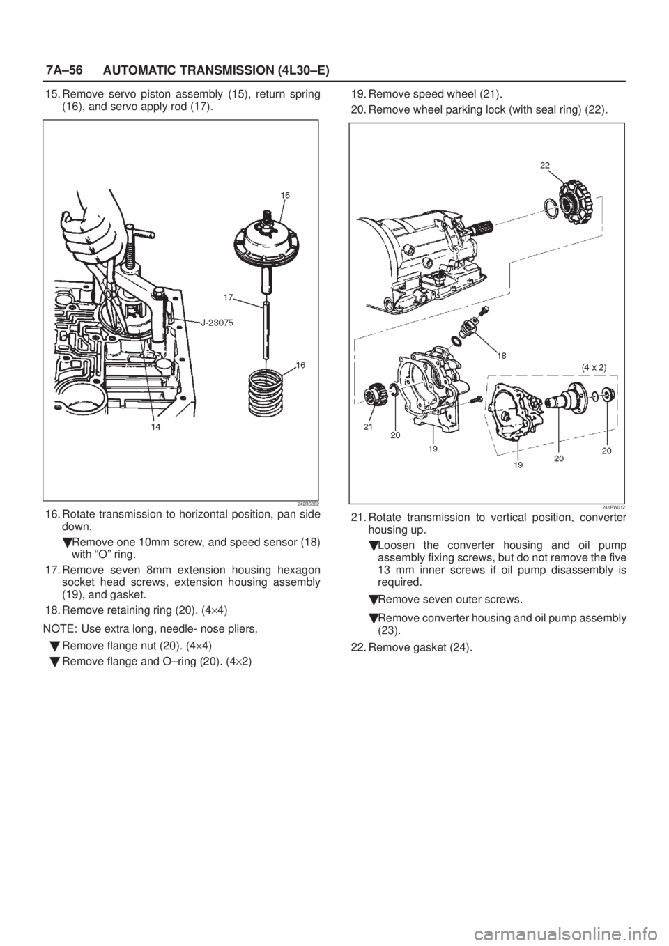
15. Remove servo piston assembly (15), return spring
(16), and servo apply rod (17).
242RS002
16. Rotate transmission to horizontal position, pan side
down.
�Remove one 10mm screw, and speed sensor (18)
with ªOº ring.
17. Remove seven 8mm extension housing hexagon
socket head screws, extension housing assembly
(19), and gasket.
18. Remove retaining ring (20). (4y4)
NOTE: Use extra long, needle- nose pliers.
�Remove flange nut (20). (4y4)
�Remove flange and O±ring (20). (4y2)19. Remove speed wheel (21).
20. Remove wheel parking lock (with seal ring) (22).241RW012
21. Rotate transmission to vertical position, converter
housing up.
�Loosen the converter housing and oil pump
assembly fixing screws, but do not remove the five
13 mm inner screws if oil pump disassembly is
required.
�Remove seven outer screws.
�Remove converter housing and oil pump assembly
(23).
22. Remove gasket (24).
Page 1641 of 2100

23. Remove selective thrust washer (25).
241RW004
24. Remove fourth clutch retainer (26).
25. Grasp turbine shaft and lift out the overrun clutch
housing assemb")
7A±57 AUTOMATIC TRANSMISSION (4L30±E)
23. Remove selective thrust washer (25).
241RW004
24. Remove fourth clutch retainer (26).
25. Grasp turbine shaft and lift out the overrun clutch
housing assembly (27) and fourth clutch plates (28).
26. Remove thrust bearing assembly (29).
27. Remove overdrive internal gear (30).28. Remove thrust washer (31).
252RS001
29. Remove adapter case and center support assembly
(with fourth clutch piston) (32).
30. Remove seal ring (33).
31. Remove selective thrust washer (34) and two O±ring
seals (35) from main case.
32. Use J±23327 and J±23327±90 compressor to
compress the fourth clutch spring retainer and
springs (37).
�Release snap ring (36) from groove.
�Remove clutch compressor and snap ring (36).
33. Remove retainer and spring assembly (37).
34. Insert two converter housing/main case screws to
hold adapter case while pulling out fourth clutch
piston (38).
�Remove fourth clutch piston assembly (38) from the
adapter case.
�Remove converter housing/main case screws.
35. Grasp intermediate shaft, twist and pull out the
second and third clutch drum assemblies with reverse
clutch plates (39) while holding onto output shaft.
Page 1642 of 2100

36. Separate second (40) and third clutch (41)
assemblies.
37. Remove thrust washer (42).
38. Remove reverse clutch plates (43 and 44) and
reverse clutch pressu")
7A±58
AUTOMATIC TRANSMISSION (4L30±E)
36. Separate second (40) and third clutch (41)
assemblies.
37. Remove thrust washer (42).
38. Remove reverse clutch plates (43 and 44) and
reverse clutch pressure plate (45).
39. Remove bearing (46) and washer (47).
40. Remove planetary carrier assembly (48).
41. Remove thrust bearing (49).
42. Remove reaction sun gear (50)
43. Remove needle bearing (51).
44. Remove brake drum (52).
45. Remove brake band (53).
46. Remove thrust bearing (54).
242RS003
47. Rotate case to horizontal position, valve body side
facing up.
�Remove spring pin (55), using cutting pliers, then
remove parking lock and selector lever assembly
(56).NOTE: Insert wire in the center of the spring pin to
prevent it from collapsing during removal. Be aware of pin
height. Protect machined face of main case.
48. Remove parking lock and range selector lever 17 mm
nut (57).
49. Remove parking lock and range selector lever (56),
and actuator assembly.
50. Remove selector shaft (58).
NOTE: Inspect the shaft for burrs before removing to
prevent damaging seal. If necessary, remove burrs by
lightly sanding with an oilstone.
249RS004
Reassembly
1. Inspect selector shaft seal, and replace it if
necessary.
NOTE: Use a seal installer when replacing the seal.
�Install selector shaft.
NOTE: Spring pin groove must be positioned inside the
case.
2. Install spring pin. Be sure the selector shaft can move
freely. Do not push the pin flush with the case surface.
Leave enough height for removal.
3. Install actuator assembly (1).
4. Install parking lock and range selector lever (2) and
new 17 mm nut. Tighten the nut to the specified
torque.
Torque: 22 Nwm (16 lb ft)
Page 1643 of 2100

249RS005
5. Rotate main case to vertical position, extension end
facing down.
�Install brake band assembly (3).
NOTE: Be sure to align servo pin area with the s")
7A±59 AUTOMATIC TRANSMISSION (4L30±E)
249RS005
5. Rotate main case to vertical position, extension end
facing down.
�Install brake band assembly (3).
NOTE: Be sure to align servo pin area with the servo hole.
6. Install thrust bearing (4).
NOTE: The case bushing acts as a guide for the thrust
bearing.
7. Install brake drum (5).
8. Install reaction sun gear (6).
9. Install needle bearing (7).
10. Inspect planetary carrier assembly (8) for wear and
damage. If necessary replace it.
�Measure pinion end play clearance with a feeler
gauge.
Clearance: 0.13mm±0.89mm (0.005 in±0.035 in)
If clearance is outside specified value, replace the
planetary carrier assembly.
248RS001
11. Install the thrust bearing (9) on the output shaft.
NOTE: Use petroleum jelly to hold the thrust bearing in
place.
12. Align planetary pinions. Each pinion is marked with
double points to indicate the master tooth space and
exactly opposite with a single point to indicate the
master tooth. The markings on the planetary carrier
consist of double lines which are to be lined up with
the double points on two opposite pinions; the single
lines are to be lined up with the single points on the
other two pinions.
�After all four pinions are lined up, slide on the third
clutch assembly. Rotate third clutch and check
mark alignment. Considering that the ring gear
tooth between the double points of one planetary
pinion is tooth number 1, count the teeth to check
that the single points on the two adjacent pinions
are between teeth 23 and 24 of the ring gear, and
that the ring gear tooth between the double points of
the opposite pinion is tooth number 46. If the ring
gear and pinions are not lined up, remove, and
realign them.
13. Install planetary carrier (8) with third clutch (12).
NOTE: Do not force. When properly aligned, the parts will
fit together easily.
248RS002
14. Remove the third clutch (12).
15. Install bearing (11) and washer (10).

13. Remove two check balls (13) from main case.
240RY001
14. Turn transmission to vertical position to drain fluid.
Return back to horizontal position when drai")