Page 1612 of 2100
7A±28
AUTOMATIC TRANSMISSION (4L30±E)
4. Remove rear console.
745R200003
5. Remove front console.
745R200004
6. Remove selector lever knob and cover assembly.
256R200001
7. Disconnect select cable.
�Refer to
Select Cable in this section.
8. Disconnect shift lock cable.
�Refer to
Shift Lock Cable in this section.
9. Disconnect harness connector.
Page 1613 of 2100

7A±29 AUTOMATIC TRANSMISSION (4L30±E)
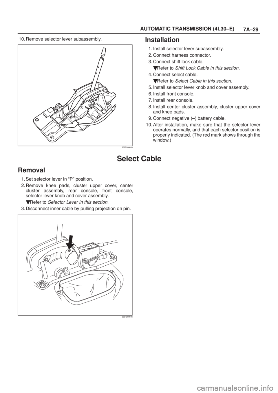
10. Remove selector lever subassembly.
256R200005
Installation
1. Install selector lever subassembly.
2. Connect harness connector.
3. Connect shift lock cable.
�Refer to
Shift Lock Cable in this section.
4. Connect select cable.
�Refer to
Select Cable in this section.
5. Install selector lever knob and cover assembly.
6. Install front console.
7. Install rear console.
8. Install center cluster assembly, cluster upper cover
and knee pads.
9. Connect negative (±) battery cable.
10. After installation, make sure that the selector lever
operates normally, and that each selector position is
properly indicated. (The red mark shows through the
window.)
Select Cable
Removal
1. Set selector lever in ªPº position.
2. Remove knee pads, cluster upper cover, center
cluster assembly, rear console, front console,
selector lever knob and cover assembly.
�Refer to
Selector Lever in this section.
3. Disconnect inner cable by pulling projection on pin.
256R200006
Page 1614 of 2100
7A±30
AUTOMATIC TRANSMISSION (4L30±E)
4. Press down claws and disconnect cable assembly.
A07RW017
5. Remove nuts that fasten grommet in select cable
assembly.
6. Disconnect inner cable.
210RW013
Page 1615 of 2100
7A±31 AUTOMATIC TRANSMISSION (4L30±E)
7. Slide sleeve and disconnect cable assembly.
A07RW082
8. Pull lock.
A07RW015
9. Draw select cable assembly into the interior side.
Page 1616 of 2100
7A±32
AUTOMATIC TRANSMISSION (4L30±E)
Installation
1. Set selector lever in ªPº position.
2. Let out select cable transmission side end from floor
hole.
3. Fit outer cable into bracket in selector lever assembly.
A07RW016
4. Set inner cable end in selector lever and push pin into
selector lever hole and inner cable end.
256R200007
Page 1617 of 2100
7A±33 AUTOMATIC TRANSMISSION (4L30±E)
5. Check that lock projects.
A07RW015
6. Connect adjust end fitting attachment to the bracket
on transmission.
7. Set select lever ªPº position and connect inner cable
to select lever.
210RW013
8. Push lock into adjust end fitting attachment.
A07RW014
9. Install grommet.
10. About following installation steps, refer to
Selector
Lever in this section.
Page 1618 of 2100

7A±34
AUTOMATIC TRANSMISSION (4L30±E)
Shift Lock Cable
Removal
1. Set ignition key in ªLOCKº position and selector lever
in ªPº position.
2. Remove knee pads, cluster upper cover, center
cluster assembly, rear console, and front console.
�Refer to
Selector Lever in this section.
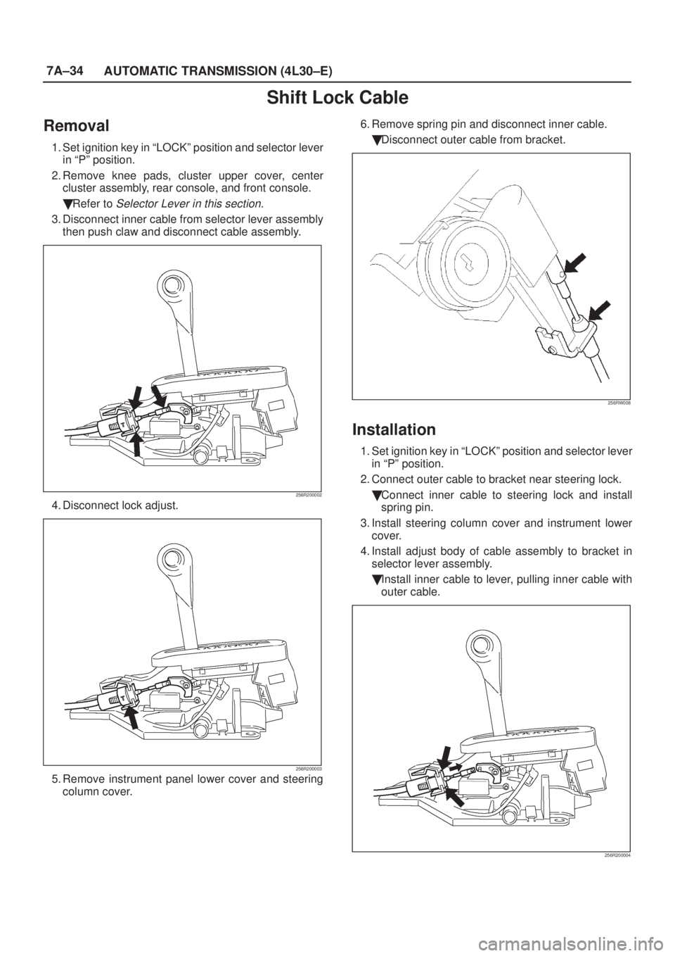
3. Disconnect inner cable from selector lever assembly
then push claw and disconnect cable assembly.
256R200002
4. Disconnect lock adjust.
256R200003
5. Remove instrument panel lower cover and steering
column cover.6. Remove spring pin and disconnect inner cable.
�Disconnect outer cable from bracket.
256RW008
Installation
1. Set ignition key in ªLOCKº position and selector lever
in ªPº position.
2. Connect outer cable to bracket near steering lock.
�Connect inner cable to steering lock and install
spring pin.
3. Install steering column cover and instrument lower
cover.
4. Install adjust body of cable assembly to bracket in
selector lever assembly.
�Install inner cable to lever, pulling inner cable with
outer cable.
256R200004
Page 1619 of 2100

7A±35 AUTOMATIC TRANSMISSION (4L30±E)
5. Check that cable moves smoothly, lightly pulling outer
cable rearward.
6. Connect lock adjust, aligning ªTº mark in the ªUpº
position.
256R200003
7. About following installation steps, refer to Selector
Lever in this section.
8. Check the shift lock operation:
a. Selector lever should not be moved out of ªPº
position with ignition key in ªLockº position.
b. Selector lever can be moved out of ªPº position with
ignition key in ªONºposition only when brake pedal
is depressed.
c. ignition key can be turned to ªLOCKº position only
when selector lever is in ªPº position (key can be
pulled out).
9. If a. and c. fail, readjust cable. If b. fails, readjust
connector wiring and brake pedal switch.
Mode Switch
Removal
1. Place selector lever in neutral.
2. Disconnect battery ground cable.
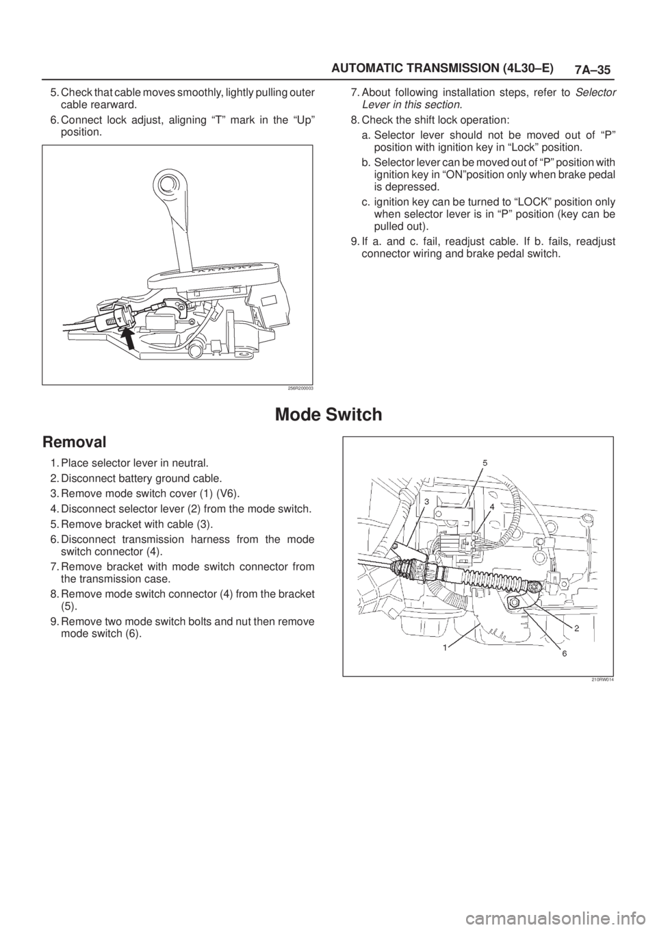
3. Remove mode switch cover (1) (V6).
4. Disconnect selector lever (2) from the mode switch.
5. Remove bracket with cable (3).
6. Disconnect transmission harness from the mode
switch connector (4).
7. Remove bracket with mode switch connector from
the transmission case.
8. Remove mode switch connector (4) from the bracket
(5).
9. Remove two mode switch bolts and nut then remove
mode switch (6).
210RW014