Page 1710 of 2100
7A1±23
Intermittent Conditions
If the Tech 2 displays a diagnostic trouble code as
intermittent, or if after a test drive a DTC does not
reappear though the detec")
TRANSMISSION CONTROL SYSTEM (4L30±E)7A1±23
Intermittent Conditions
If the Tech 2 displays a diagnostic trouble code as
intermittent, or if after a test drive a DTC does not
reappear though the detection conditions for this DTC are
present, the problem is most likely a faulty electrical
connection or loose wiring. Terminals and grounds should
always be the prime suspect. Intermittents rarely occur
inside sophisticated electronic components such as the
PCM.
Use the DTC information to understand which wires and
sensors are involved.
When an intermittent problem is encountered, check
suspect circuits for:
1. Poor terminal to wire connection.
2. Terminals not fully seated in the connector body
(backed out).
3. Improperly formed or damaged terminals.
4. Loose, dirty, or corroded ground connections:
HINT: Any time you have an intermittent in more than
one circuit, check whether the circuits share a
common ground connection.5. Pinched or damaged wires.
6. Electro±Magnetic Interference (EMI):
HINT: Check that all wires are properly routed away
from coil, and generator. Also check for improperly
installed electrical options, such as lights, 2±way
radios, etc.
Use the F2: SNAPSHOT mode of the Tech 2 to help
isolate the cause of an intermittent fault. The snapshot
mode will record information before and after the problem
occurs. Set the snapshot to ªtriggerº on the suspect DTC.
If you notice the reported symptom during the test drive,
trigger the snapshot manually.
After the snapshot has been triggered, command the
Tech 2 to play back the flow of data recorded from each of
the various sensors. Signs of an intermittent fault in a
sensor circuit are sudden unexplainable jump in data
values out of the normal range.
Transmission And PCM Identification
The chart below contains a list of all important information
concerning rear axle ratio, Powertrain Control Module
(PCM), and transmission identification.
VEHICLE
Rr axlePCMTRANSMISSION
TypeEngine
Rr axle
RatioISUZU Parts No.Calibration
CodeIsuzu Part No.Model Code
Isuzu /35LV64 3008±97287±830±0G268±96023±779±0YB (4y4)
Axiom3.5L V64.3008±09389±969±0G268±96024±169±0YE (4y2)
240R200001
Page 1798 of 2100

8A±22LIGHTING SYSTEM
Light NameBulb No.Rated
PowerNumber of
BulbsLens ColorRemarks
Headlight9005/900660w/51w2WhiteHalogen
Front Turn signal Light/
Front Side Marker Light/Parking Light1157NA27w/8w2Amber
Rear Turn Signal Light744021w2Amber
Backup Light92118w2White
Taillight/Stoplight744321w/5w2Red
High Mounted Stoplight92118w2Red
License Plate Light (Tailgate type)1685w2White
Map LightÐ8w2White
Dome LightÐ10w1White
Luggage Room LightÐ5w1White
Courtesy LightÐ3.4w4White
Check TransÐ1.4w1RedMeter
A/T Oil TempÐ1.4w1RedMeter
Cruise SetÐ1.4w1GreenMeter
Power DriveÐ1.4w1AmberMeter
Winter DriveÐ1.4w1GreenMeter
Turn SignalÐ1.4w2GreenMeter
Check TODÐ1.4w1RedMeter
High BeamÐ1.4w1BlueMeter
ABSÐ1.4w1AmberMeter
Seat BeltÐ2w1RedMeter
Indicator/Warning
Malfunction Indicator
(Check Engine)Ð1.4w1AmberMeter
Indicator/Warning
LightLow FuelÐ1.4w1AmberMeterg
Reduced PowerÐ1.4w1AmberMeter
Sports ModeÐ1.4w1GreenMeter
TOD FrontÐ1.1w1GreenMeter
TOD AutoÐ1.1w1GreenMeter
TOD RearÐ1.1w1GreenMeter
Oil PressureÐ1.4w1RedMeter
Brake SystemÐ1.4w1RedMeter
ChargeÐ1.4w1RedMeter
A/T Shift PositionÐ1.1w7
P,N,D,3,2,L
:Green
R: Amber
Meter
Air BagÐ2w1RedMeter
Illumination LightMeterÐ3.4w4Meter
Shift leverÐ1.4w1WhiteShift lever
Vanity MirrorÐ2w2WhiteSun Visor
Cigarette LighterÐ1.4w1WhiteCigarette
Lighter
AshtrayÐ1.4w1WhiteAshtray
Page 1871 of 2100

METER AND GAUGE8E±5
Connector A
TerminalFunction
1Ð
2Intelligent suspension indicator light
3TOD indicator light ªRearº
4Ð
5TOD indicator light ªAUTOº
6Ð
7TOD indicator light ªFrontº
8A/T shift indicator light ª3º
9A/T shift indicator light ªDº
10A/T shift indicator light ª2º
11SRS ± air bag warning light
12Ground
13Battery
14Stater switch
15A/T oil temperature warning light
16Seat belt indicator light
17Charge warning light
18Ð
19Ð
20Ð
21A/T shift indicator light ªLº
22ABS warning light
23Ð
24Ð
25Reduced power warning light
26Oil pressure warning light
27Check trans warning light
28MIL(check engine) warning light
29Check TOD
30Engine coolant temperature gauge
Connector B
TerminalFunction
1A/T shift indicator light ªRº
2A/T shift indicator light
3A/T shift indicator light ªNº
4A/T shift indicator light ªPº
5Illumination light
6Engine revolution pulse
7Speed sensor pulse
8Turn signal indicator light (LH)
9Brake warning light
10High beam indicator light (+)
11High beam indicator light (±)
12Turn signal indicator light (RH)
13Turn signal indicator light
14Ð
15Illumination light
16Ground
Connector C
TerminalFunction
1Starter switch
2Ð
3Fuel gauge
4Low fuel warning light
5Cruise set indicator light
6Ð
7Ð
8Ð
9Ð
10Sport mode indicator light
11Ð
12Winter drive indicator light
13Power drive indicator light
14Ð
Page 1892 of 2100
8F±16BODY STRUCTURE
Removal
1. Disconnect the battery ground cable.
2. Remove the front bumper fascia assembly.
�Refer to
Front Bumper in this section.
3. Remove the front turn signal light assembly.
�Remove the fixing screw and disconnect the
connector.
610R200008
4. Remove the rocker cover assembly.
�Refer to
Rocker Cover Assembly in Exterior/Interior
Trim section.
5. Remove the inner liner.
647RY00003
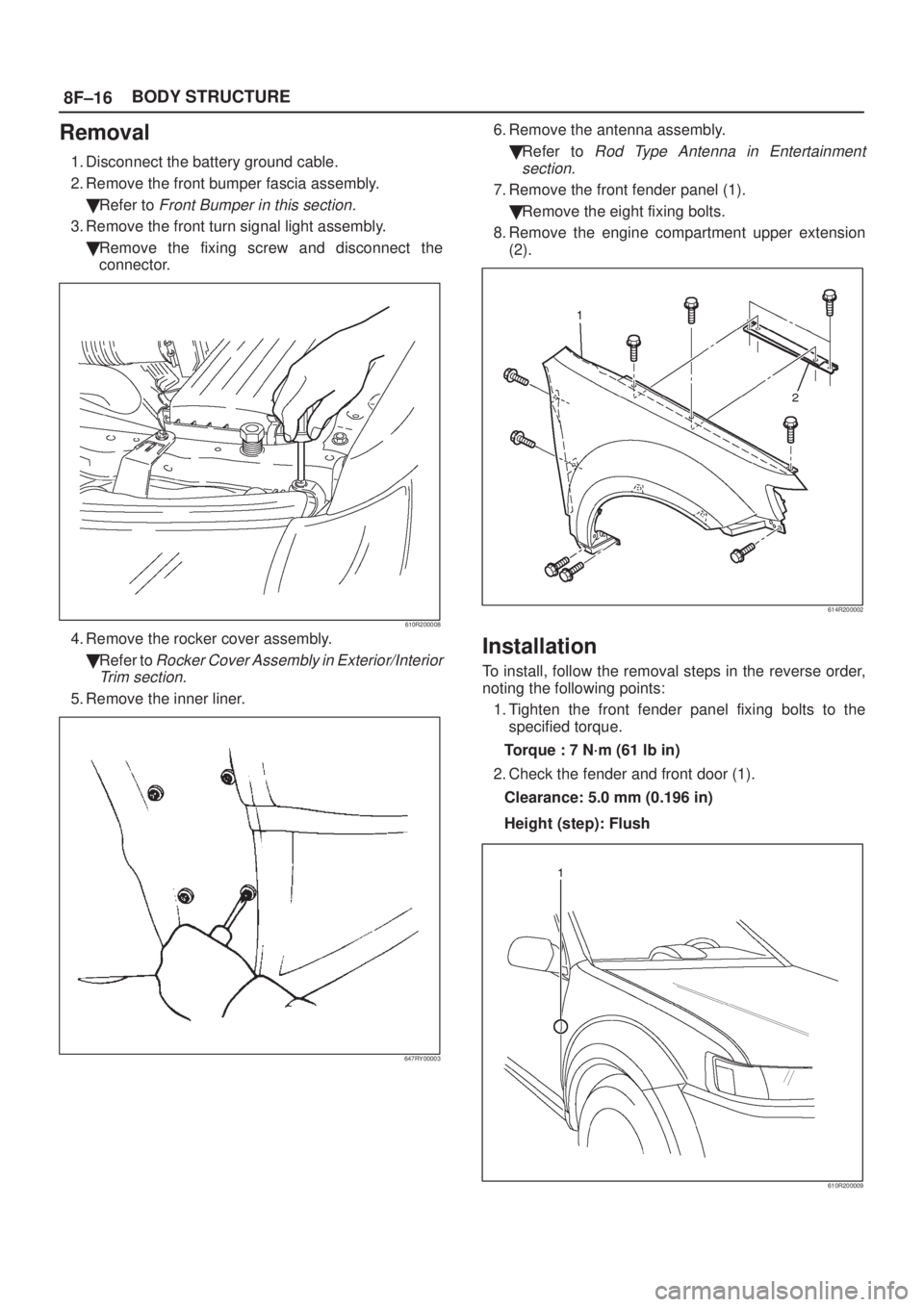
6. Remove the antenna assembly.
�Refer to
Rod Type Antenna in Entertainment
section.
7. Remove the front fender panel (1).
�Remove the eight fixing bolts.
8. Remove the engine compartment upper extension
(2).
614R200002
Installation
To install, follow the removal steps in the reverse order,
noting the following points:
1. Tighten the front fender panel fixing bolts to the
specified torque.
Torque : 7 N´m (61 lb in)
2. Check the fender and front door (1).
Clearance: 5.0 mm (0.196 in)
Height (step): Flush
610R200009