2002 DODGE RAM clutch
[x] Cancel search: clutchPage 425 of 2255
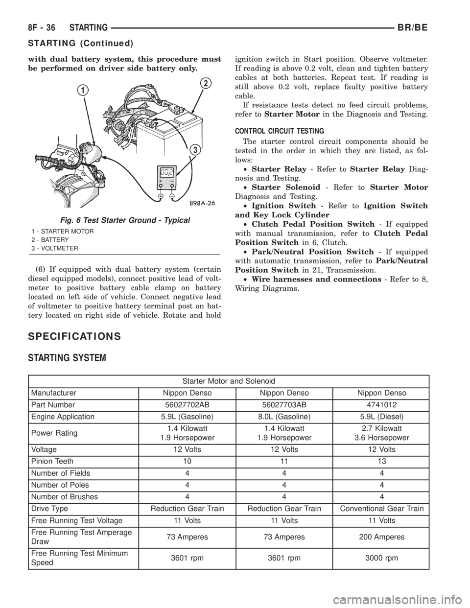
with dual battery system, this procedure must
be performed on driver side battery only.
(6) If equipped with dual battery system (certain
diesel equipped models), connect positive lead of volt-
meter to positive battery cable clamp on battery
located on left side of vehicle. Connect negative lead
of voltmeter to positive battery terminal post on bat-
tery located on right side of vehicle. Rotate and holdignition switch in Start position. Observe voltmeter.
If reading is above 0.2 volt, clean and tighten battery
cables at both batteries. Repeat test. If reading is
still above 0.2 volt, replace faulty positive battery
cable.
If resistance tests detect no feed circuit problems,
refer toStarter Motorin the Diagnosis and Testing.
CONTROL CIRCUIT TESTING
The starter control circuit components should be
tested in the order in which they are listed, as fol-
lows:
²Starter Relay- Refer toStarter RelayDiag-
nosis and Testing.
²Starter Solenoid- Refer toStarter Motor
Diagnosis and Testing.
²Ignition Switch- Refer toIgnition Switch
and Key Lock Cylinder
²Clutch Pedal Position Switch- If equipped
with manual transmission, refer toClutch Pedal
Position Switchin 6, Clutch.
²Park/Neutral Position Switch- If equipped
with automatic transmission, refer toPark/Neutral
Position Switchin 21, Transmission.
²Wire harnesses and connections- Refer to 8,
Wiring Diagrams.
SPECIFICATIONS
STARTING SYSTEM
Starter Motor and Solenoid
Manufacturer Nippon Denso Nippon Denso Nippon Denso
Part Number 56027702AB 56027703AB 4741012
Engine Application 5.9L (Gasoline) 8.0L (Gasoline) 5.9L (Diesel)
Power Rating1.4 Kilowatt
1.9 Horsepower1.4 Kilowatt
1.9 Horsepower2.7 Kilowatt
3.6 Horsepower
Voltage 12 Volts 12 Volts 12 Volts
Pinion Teeth 10 11 13
Number of Fields 4 4 4
Number of Poles 4 4 4
Number of Brushes 4 4 4
Drive Type Reduction Gear Train Reduction Gear Train Conventional Gear Train
Free Running Test Voltage 11 Volts 11 Volts 11 Volts
Free Running Test Amperage
Draw73 Amperes 73 Amperes 200 Amperes
Free Running Test Minimum
Speed3601 rpm 3601 rpm 3000 rpm
Fig. 6 Test Starter Ground - Typical
1 - STARTER MOTOR
2 - BATTERY
3 - VOLTMETER
8F - 36 STARTINGBR/BE
STARTING (Continued)
Page 426 of 2255
Starter Motor and Solenoid
Solenoid Closing Maximum
Voltage Required7.5 Volts 7.5 Volts 8.0 Volts
* Cranking Amperage Draw
Test125 - 250 Amperes 125 - 250 Amperes 450 - 700 Amperes
* Test at operating temperature. Cold engine, tight (new) engine, or heavy oil will increase starter amperage draw.
SPECIFICATIONS - TORQUE - STARTING
SYSTEM
DESCRIPTION N´m Ft. Lbs. In. Lbs.
Battery Cable Eyelet Nut
at Solenoid (large nut -
gas engines)25 19 221
Battery Cable Eyelet Nut
at Solenoid (large nut -
diesel engine)14 - 120
Starter Solenoid Nut
(small nut - diesel engine)6-55
Starter Mounting Bolts -
Gas Engines68 50 -
Starter Mounting Nut -
Gas Engines68 50 -
Starter Mounting Bolts -
Diesel43 32 -
STARTER MOTOR
DESCRIPTION
The starter motors used for the 5.9L diesel engine
and the 8.0L gasoline engine available in this model
are not interchangeable with each other, or with the
starter motors used for the other available engines.
The starter motor for the 5.9L diesel engine is
mounted with three screws to the flywheel housing
on the left side of the engine. The starter motor for
the 8.0L gasoline engine is mounted with two screws
to the flange on the left rear corner of the engine
block, while the starter motor for the 5.9L Gas
engine is mounted with one screw, a stud and a nut
to the manual transmission clutch housing or auto-
matic transmission torque converter housing and is
located on the left side of the engine.
Each of these starter motors incorporates several
of the same features to create a reliable, efficient,
compact, lightweight and powerful unit. The electric
motors of all of these starters have four brushes con-
tacting the motor commutator, and feature four elec-
tromagnetic field coils wound around four pole shoes.
The 5.9L and 8.0L gasoline engine starter motors are
rated at 1.4 kilowatts (about 1.9 horsepower) outputat 12 volts, while the 5.9L diesel engine starter
motor is rated at 2.7 kilowatts (about 3.6 horse-
power) output at 12 volts.
All of these starter motors are serviced only as a
unit with their starter solenoids, and cannot be
repaired. If either component is faulty or damaged,
the entire starter motor and starter solenoid unit
must be replaced.
OPERATION
These starter motors are equipped with a gear
reduction (intermediate transmission) system. The
gear reduction system consists of a gear that is inte-
gral to the output end of the electric motor armature
shaft that is in continual engagement with a larger
gear that is splined to the input end of the starter
pinion gear shaft. This feature makes it possible to
reduce the dimensions of the starter. At the same
time, it allows higher armature rotational speed and
delivers increased torque through the starter pinion
gear to the starter ring gear.
The starter motors for all engines are activated by
an integral heavy duty starter solenoid switch
mounted to the overrunning clutch housing. This
electromechanical switch connects and disconnects
BR/BESTARTING 8F - 37
STARTING (Continued)
Page 427 of 2255
the feed of battery voltage to the starter motor, also
engaging and disengaging the starter pinion gear
with the starter ring gear.
All starter motors use an overrunning clutch and
starter pinion gear unit to engage and drive a starter
ring gear that is integral to the flywheel (manual
transmission), torque converter or torque converter
drive plate (automatic transmission) mounted on the
rear crankshaft flange.
DIAGNOSIS AND TESTING - STARTER MOTOR
Correct starter motor operation can be confirmed
by performing the following free running bench test.
This test can only be performed with starter motor
removed from vehicle. Refer to Starter Specifications
for starter motor specifications.
(1) Remove starter motor from vehicle. Refer to
Starter MotorRemoval and Installation.
(2) Mount starter motor securely in a soft-jawed
bench vise. The vise jaws should be clamped on
mounting flange of starter motor. Never clamp on
starter motor by field frame.
(3) Connect suitable volt-ampere tester and 12-volt
battery to starter motor in series, and set ammeter to
100 ampere scale (250 ampere scale for diesel engine
starters). See instructions provided by manufacturer
of volt-ampere tester being used.
(4) Install jumper wire from solenoid terminal to
solenoid battery terminal. The starter motor should
operate. If starter motor fails to operate, replace
faulty starter motor assembly.
(5) Adjust carbon pile load of tester to obtain free
running test voltage. Refer to Specifications for the
starter motor free running test voltage specifications.
(6) Note reading on ammeter and compare this
reading to free running test maximum amperage
draw. Refer to Specifications for starter motor free
running test maximum amperage draw specifica-
tions.
(7) If ammeter reading exceeds maximum amper-
age draw specification, replace faulty starter motor
assembly.
STARTER MOTOR SOLENOID
This test can only be performed with starter motor
removed from vehicle.
(1) Remove starter motor. Refer toStarter Motor
Removal and Installation.
(2) Disconnect wire from solenoid field coil termi-
nal.
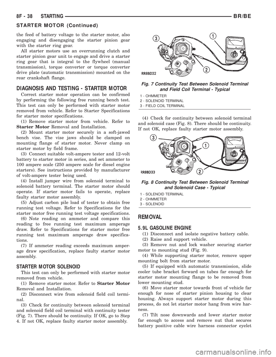
(3) Check for continuity between solenoid terminal
and solenoid field coil terminal with continuity tester
(Fig. 7). There should be continuity. If OK, go to Step
4. If not OK, replace faulty starter motor assembly.(4) Check for continuity between solenoid terminal
and solenoid case (Fig. 8). There should be continuity.
If not OK, replace faulty starter motor assembly.
REMOVAL
5.9L GASOLINE ENGINE
(1) Disconnect and isolate negative battery cable.
(2) Raise and support vehicle.
(3) Remove nut and lock washer securing starter
motor to mounting stud (Fig. 9).
(4) While supporting starter motor, remove upper
mounting bolt from starter motor.
(5) If equipped with automatic transmission, slide
cooler tube bracket forward on tubes far enough for
starter motor mounting flange to be removed from
lower mounting stud.
(6) Move starter motor towards front of vehicle far
enough for nose of starter pinion housing to clear
housing. Always support starter motor during this
process, do not let starter motor hang from wire har-
ness.
(7) Tilt nose downwards and lower starter motor
far enough to access and remove nut that secures
battery positive cable wire harness connector eyelet
Fig. 7 Continuity Test Between Solenoid Terminal
and Field Coil Terminal - Typical
1 - OHMMETER
2 - SOLENOID TERMINAL
3 - FIELD COIL TERMINAL
Fig. 8 Continuity Test Between Solenoid Terminal
and Solenoid Case - Typical
1 - SOLENOID TERMINAL
2 - OHMMETER
3 - SOLENOID
8F - 38 STARTINGBR/BE
STARTER MOTOR (Continued)
Page 430 of 2255
STARTER MOTOR RELAY
DESCRIPTION
The starter relay is an electromechanical device
that switches battery current to the pull-in coil of the
starter solenoid when ignition switch is turned to
Start position. The starter relay is located in the
Power Distribution Center (PDC) in the engine com-
partment. See PDC cover for relay identification and
location.
The starter relay is a International Standards
Organization (ISO) relay. Relays conforming to ISO
specifications have common physical dimensions, cur-
rent capacities, terminal patterns, and terminal func-
tions.
The starter relay cannot be repaired or adjusted
and, if faulty or damaged, it must be replaced.
OPERATION
The ISO relay consists of an electromagnetic coil, a
resistor or diode, and three (two fixed and one mov-
able) electrical contacts. The movable (common feed)
relay contact is held against one of the fixed contacts
(normally closed) by spring pressure. When electro-
magnetic coil is energized, it draws the movable con-
tact away from normally closed fixed contact, and
holds it against the other (normally open) fixed con-
tact.
When electromagnetic coil is de-energized, spring
pressure returns movable contact to normally closed
position. The resistor or diode is connected in parallel
with electromagnetic coil within relay, and helps to
dissipate voltage spikes produced when coil is de-en-
ergized.
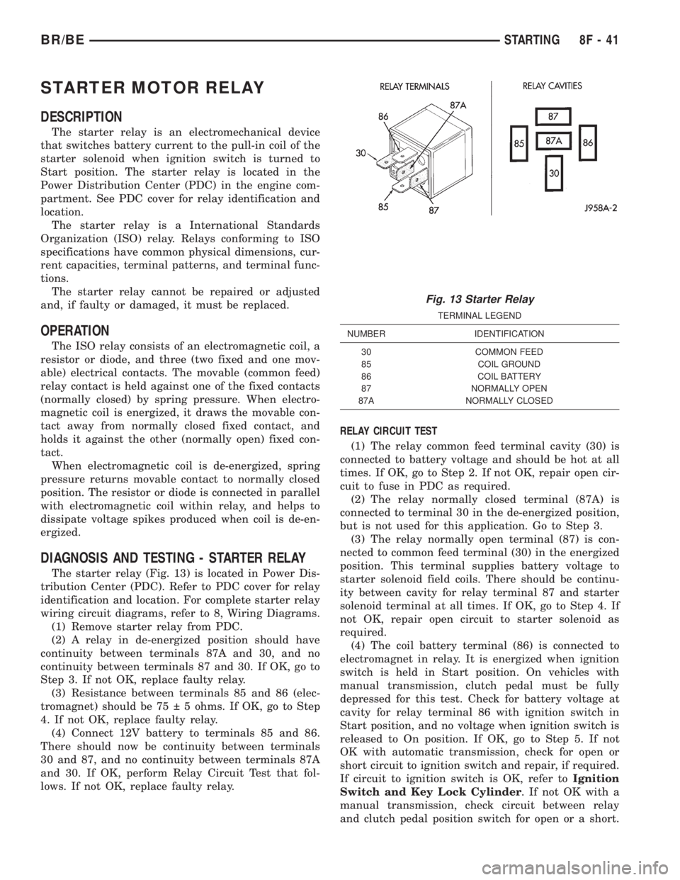
DIAGNOSIS AND TESTING - STARTER RELAY
The starter relay (Fig. 13) is located in Power Dis-
tribution Center (PDC). Refer to PDC cover for relay
identification and location. For complete starter relay
wiring circuit diagrams, refer to 8, Wiring Diagrams.
(1) Remove starter relay from PDC.
(2) A relay in de-energized position should have
continuity between terminals 87A and 30, and no
continuity between terminals 87 and 30. If OK, go to
Step 3. If not OK, replace faulty relay.
(3) Resistance between terminals 85 and 86 (elec-
tromagnet) should be 75 5 ohms. If OK, go to Step
4. If not OK, replace faulty relay.
(4) Connect 12V battery to terminals 85 and 86.
There should now be continuity between terminals
30 and 87, and no continuity between terminals 87A
and 30. If OK, perform Relay Circuit Test that fol-
lows. If not OK, replace faulty relay.RELAY CIRCUIT TEST
(1) The relay common feed terminal cavity (30) is
connected to battery voltage and should be hot at all
times. If OK, go to Step 2. If not OK, repair open cir-
cuit to fuse in PDC as required.
(2) The relay normally closed terminal (87A) is
connected to terminal 30 in the de-energized position,
but is not used for this application. Go to Step 3.
(3) The relay normally open terminal (87) is con-
nected to common feed terminal (30) in the energized
position. This terminal supplies battery voltage to
starter solenoid field coils. There should be continu-
ity between cavity for relay terminal 87 and starter
solenoid terminal at all times. If OK, go to Step 4. If
not OK, repair open circuit to starter solenoid as
required.
(4) The coil battery terminal (86) is connected to
electromagnet in relay. It is energized when ignition
switch is held in Start position. On vehicles with
manual transmission, clutch pedal must be fully
depressed for this test. Check for battery voltage at
cavity for relay terminal 86 with ignition switch in
Start position, and no voltage when ignition switch is
released to On position. If OK, go to Step 5. If not
OK with automatic transmission, check for open or
short circuit to ignition switch and repair, if required.
If circuit to ignition switch is OK, refer toIgnition
Switch and Key Lock Cylinder. If not OK with a
manual transmission, check circuit between relay
and clutch pedal position switch for open or a short.
Fig. 13 Starter Relay
TERMINAL LEGEND
NUMBER IDENTIFICATION
30 COMMON FEED
85 COIL GROUND
86 COIL BATTERY
87 NORMALLY OPEN
87A NORMALLY CLOSED
BR/BESTARTING 8F - 41
Page 431 of 2255
If circuit is OK, refer toClutch Pedal Position
Switchin 6 , Clutch.
(5) The coil ground terminal (85) is connected to
the electromagnet in the relay. On vehicles with
manual transmission, it is grounded at all times. On
vehicles with automatic transmission, it is grounded
through park/neutral position switch only when gear-
shift selector lever is in Park or Neutral positions.
Check for continuity to ground at cavity for relay ter-
minal 85. If not OK with manual transmission,
repair circuit to ground as required. If not OK with
automatic transmission, check for pen or short circuit
to park/neutral position switch and repair, if
required. If circuit to park/neutral position switch is
OK, refer toPark/Neutral Position Switchin 21,
Transmission.
REMOVAL
(1) Disconnect and isolate negative battery cable
(both negative cables if diesel).
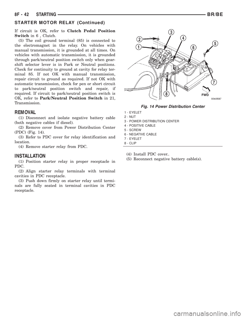
(2) Remove cover from Power Distribution Center
(PDC) (Fig. 14).
(3) Refer to PDC cover for relay identification and
location.
(4) Remove starter relay from PDC.
INSTALLATION
(1) Position starter relay in proper receptacle in
PDC.
(2) Align starter relay terminals with terminal
cavities in PDC receptacle.
(3) Push down firmly on starter relay until termi-
nals are fully seated in terminal cavities in PDC
receptacle.(4) Install PDC cover..
(5) Reconnect negative battery cable(s).
Fig. 14 Power Distribution Center
1 - EYELET
2 - NUT
3 - POWER DISTRIBUTION CENTER
4 - POSITIVE CABLE
5 - SCREW
6 - NEGATIVE CABLE
7 - EYELET
8 - CLIP
8F - 42 STARTINGBR/BE
STARTER MOTOR RELAY (Continued)
Page 625 of 2255

DESCRIPTION - VEHICLE SPEED INPUT
Gas Engines and/or Diesel With Automatic Trans.
The Vehicle Speed Sensor (VSS) is no longer used
for any Dodge Truck.
Vehicle speed and distance covered are measured
by the Rear Wheel Speed Sensor. The sensor is
mounted to the rear axle. A signal is sent from this
sensor to the Controller Antilock Brake (CAB) com-
puter. A signal is then sent from the CAB to the Pow-
ertrain Control Module (PCM) to determine vehicle
speed and distance covered. The PCM will then
determine strategies for speed control system opera-
tion.
Diesel With Manual Trans.
The Vehicle Speed Sensor (VSS) is no longer used
for any Dodge Truck.
Vehicle speed and distance covered are measured
by the Rear Wheel Speed Sensor. The sensor is
mounted to the rear axle. A signal is sent from this
sensor to the Controller Antilock Brake (CAB) com-
puter. A signal is then sent from the CAB to the
Engine Control Module (ECM) to determine vehicle
speed and distance covered. The ECM will then
determine strategies for speed control system opera-
tion.
OPERATION - SPEED CONTROL SYSTEM
Gas Engines and/or Diesel With Automatic Trans.
When speed control is selected by depressing the
ON switch, the PCM allows a set speed to be stored
in PCM RAM for speed control. To store a set speed,
depress the SET switch while the vehicle is moving
at a speed between 35 and 85 mph. In order for the
speed control to engage, the brakes cannot be
applied, nor can the gear selector be indicating the
transmission is in Park or Neutral.
The speed control can be disengaged manually by:
²Stepping on the brake pedal.
²Depressing the OFF switch.
²Depressing the CANCEL switch.
²Depressing the clutch pedal (if equipped).
NOTE: Depressing the OFF switch or turning off the
ignition switch will erase the set speed stored in
the PCM.
For added safety, the speed control system is pro-
grammed to disengage for any of the following condi-
tions:
²An indication of Park or Neutral.
²A rapid increase of rpm (indication that the
clutch has been disengaged).²Excessive engine rpm (indicates that the trans-
mission may be in a low gear).
²The speed signal increases at a rate of 10 mph
per second (indicates that the coefficient of friction
between the road surface and tires is extremely low).
²The speed signal decreases at a rate of 10 mph
per second (indicates that the vehicle may have
decelerated at an extremely high rate).
Once the speed control has been disengaged,
depressing the RES/ACCEL switch (when speed is
greater than 30 mph) restores the vehicle to the tar-
get speed that was stored in the PCM.
While the speed control is engaged, the driver can
increase the vehicle speed by depressing the RES/AC-
CEL switch. The new target speed is stored in the
PCM when the RES/ACCEL is released. The PCM
also has a9tap-up9feature in which vehicle speed
increases at a rate of approximately 2 mph for each
momentary switch activation of the RES/ACCEL
switch.
A ªtap downº feature is used to decelerate without
disengaging the speed control system. To decelerate
from an existing recorded target speed, momentarily
depress the COAST switch. For each switch activa-
tion, speed will be lowered approximately 1 mph.
Diesel With Manual Trans.
When speed control is selected by depressing the
ON switch, the Engine Control Module (ECM) allows
a set speed to be stored in ECM RAM for speed con-
trol. To store a set speed, depress the SET switch
while the vehicle is moving at a speed between 35
and 85 mph. In order for the speed control to engage,
the brakes cannot be applied.The speed control can
be disengaged manually by:
²Stepping on the brake pedal.
²Depressing the OFF switch.
²Depressing the CANCEL switch.
²Depressing the clutch pedal.
NOTE: Depressing the OFF switch or turning off the
ignition switch will erase the set speed stored in
the ECM.
For added safety, the speed control system is pro-
grammed to disengage for any of the following condi-
tions:
²A rapid increase of rpm (indication that the
clutch has been disengaged).
²Excessive engine rpm (indicates that the trans-
mission may be in a low gear).
²The speed signal increases at a rate of 10 mph
per second (indicates that the coefficient of friction
between the road surface and tires is extremely low).
²The speed signal decreases at a rate of 10 mph
per second (indicates that the vehicle may have
decelerated at an extremely high rate).
8P - 2 SPEED CONTROLBR/BE
SPEED CONTROL (Continued)
Page 635 of 2255
(4) Insert servo studs through holes in servo cable
sleeve.
(5) Install servo mounting nuts and tighten to 8.5
N´m (75 in. lbs.) torque.
(6) Connect vacuum line to servo.
(7) Connect electrical connector to servo terminals.
(8) Connect servo cable to throttle body. Refer to
Servo Cable Removal/Installation in this group.
(9) Install battery tray. Tighten all battery tray
mounting hardware to 16 N´m (140 in. lbs.) torque.
(10) Position battery into battery tray.
(11) If equipped, install battery heat shield.
(12) Install battery holddown clamp. Tighten bolt
to 4 N´m (35 in. lbs.) torque.
(13) Connect positive battery cable to battery.
(14) Connect negative battery cable to battery.
(15) Before starting engine, operate accelerator
pedal to check for any binding.
INSTALLATION - DIESEL WITH AUTO. TRANS.
(1) Position servo to mounting bracket.
(2) Align hole in cable connector with hole in servo
pin. Install cable-to-servo retaining clip.
(3) Insert servo studs through holes in servo
mounting bracket.
(4) Insert servo studs through holes in servo cable
sleeve.
(5) Install servo mounting nuts and tighten to 8.5
N´m (75 in. lbs.) torque.
(6) Connect vacuum line to servo.
(7) Connect electrical connector to servo terminals.
(8) Connect servo cable to throttle lever by push-
ing cable connector rearward onto lever pin while
holding lever forward.
(9) Install battery tray. Tighten all battery tray
mounting hardware to 16 N´m (140 in. lbs.) torque.
(10) Position battery into battery tray.
(11) If equipped, install battery heat shield.
(12) Install battery holddown clamp. Tighten bolt
to 4 N´m (35 in. lbs.) torque.
(13) Connect positive battery cable to battery.
(14) Connect negative battery cables to both bat-
teries.
(15) Before starting engine, operate accelerator
pedal to check for any binding.
(16) Install cable/lever cover.
SWITCH
DESCRIPTION
Gas Engines and Diesel With Auto. Trans.
There are two separate switch pods that operate
the speed control system. The steering-wheel-
mounted switches use multiplexed circuits to provideinputs to the Powertrain Control Module (PCM) for
ON, OFF, RESUME, ACCELERATE, SET, DECEL
and CANCEL modes. Refer to the owner's manual for
more information on speed control switch functions
and setting procedures.
The individual switches cannot be repaired. If one
switch fails, the entire switch module must be
replaced.
Diesel With Manual Trans.
There are two separate switch pods that operate
the speed control system. The steering-wheel-
mounted switches use multiplexed circuits to provide
inputs to the Engine Control Module (ECM) for ON,
OFF, RESUME, ACCELERATE, SET, DECEL and
CANCEL modes. Refer to the owner's manual for
more information on speed control switch functions
and setting procedures.
The individual switches cannot be repaired. If one
switch fails, the entire switch module must be
replaced.
OPERATION
Gas Engines and Diesel With Auto. Trans.
When speed control is selected by depressing the
ON, OFF switch, the Powertrain Control Module
(PCM) allows a set speed to be stored in its RAM for
speed control. To store a set speed, depress the SET
switch while the vehicle is moving at a speed
between approximately 35 and 85 mph. In order for
the speed control to engage, the brakes cannot be
applied, nor can the gear selector be indicating the
transmission is in Park or Neutral.
The speed control can be disengaged manually by:
²Stepping on the brake pedal.
²Depressing the OFF switch.
²Depressing the CANCEL switch.
The speed control can be disengaged also by any of
the following conditions:
²An indication of Park or Neutral.
²The vehicle speed signal increases at a rate of
10 mph per second (indicates that the co-efficient of
friction between the road surface and tires is
extremely low).
²Depressing the clutch pedal.
²Excessive engine rpm (indicates that the trans-
mission may be in a low gear).
²The vehicle speed signal decreases at a rate of
10 mph per second (indicates that the vehicle may
have decelerated at an extremely high rate).
²If the actual speed is not within 20 mph of the
set speed.
The previous disengagement conditions are pro-
grammed for added safety.
8P - 12 SPEED CONTROLBR/BE
SPEED CONTROL SERVO (Continued)
Page 636 of 2255
Once the speed control has been disengaged,
depressing the ACCEL switch restores the vehicle to
the target speed that was stored in the PCM's RAM.
NOTE: Depressing the OFF switch will erase the set
speed stored in the PCM's RAM.
If, while the speed control is engaged, the driver
wishes to increase vehicle speed, the PCM is pro-
grammed for an acceleration feature. With the
ACCEL switch held closed, the vehicle accelerates
slowly to the desired speed. The new target speed is
stored in the PCM's RAM when the ACCEL switch is
released. The PCM also has a9tap-up9feature in
which vehicle speed increases at a rate of approxi-
mately 2 mph for each momentary switch activation
of the ACCEL switch.
The PCM also provides a means to decelerate with-
out disengaging speed control. To decelerate from an
existing recorded target speed, depress and hold the
COAST switch until the desired speed is reached.
Then release the switch. The ON, OFF switch oper-
ates two components: the PCM's ON, OFF input, and
the battery voltage to the brake switch, which powers
the speed control servo.
Diesel With Manual Trans.
When speed control is selected by depressing the
ON, OFF switch, the Engine Control Module (ECM)
allows a set speed to be stored in its RAM for speed
control. To store a set speed, depress the SET switch
while the vehicle is moving at a speed between
approximately 35 and 85 mph. In order for the speed
control to engage, the brakes cannot be applied.
The speed control can be disengaged manually by:
²Stepping on the brake pedal.
²Depressing the OFF switch.
²Depressing the CANCEL switch.
The speed control can be disengaged also by any of
the following conditions:
²The vehicle speed signal increases at a rate of
10 mph per second (indicates that the co-efficient of
friction between the road surface and tires is
extremely low).
²Depressing the clutch pedal.
²Excessive engine rpm (indicates that the trans-
mission may be in a low gear).
²The vehicle speed signal decreases at a rate of
10 mph per second (indicates that the vehicle may
have decelerated at an extremely high rate).
²If the actual speed is not within 20 mph of the
set speed.The previous disengagement conditions are pro-
grammed for added safety.
Once the speed control has been disengaged,
depressing the ACCEL switch restores the vehicle to
the target speed that was stored in the ECM's RAM.
NOTE: Depressing the OFF switch will erase the set
speed stored in the ECM's RAM.
If, while the speed control is engaged, the driver
wishes to increase vehicle speed, the ECM is pro-
grammed for an acceleration feature. With the
ACCEL switch held closed, the vehicle accelerates
slowly to the desired speed. The new target speed is
stored in the ECM's RAM when the ACCEL switch is
released. The ECM also has a9tap-up9feature in
which vehicle speed increases at a rate of approxi-
mately 2 mph for each momentary switch activation
of the ACCEL switch.
The ECM also provides a means to decelerate with-
out disengaging speed control. To decelerate from an
existing recorded target speed, depress and hold the
COAST switch until the desired speed is reached.
Then release the switch. The ON, OFF switch oper-
ates two components: the ECM's ON, OFF input, and
the battery voltage to the brake switch, which powers
the speed control servo.
REMOVAL
WARNING: BEFORE BEGINNING ANY AIRBAG SYS-
TEM COMPONENT REMOVAL OR INSTALLATION,
REMOVE AND ISOLATE THE NEGATIVE (-)
CABLE(S) FROM THE BATTERY. THIS IS THE ONLY
SURE WAY TO DISABLE THE AIRBAG SYSTEM.
THEN WAIT TWO MINUTES FOR SYSTEM CAPACI-
TOR TO DISCHARGE BEFORE FURTHER SYSTEM
SERVICE. FAILURE TO DO THIS COULD RESULT IN
ACCIDENTAL AIRBAG DEPLOYMENT AND POSSI-
BLE INJURY.
(1) Disconnect and isolate negative battery
cable(s).
(2) Remove airbag module. Refer to 8, Restraint
Systems for procedures.
(3) Remove switch-to-steering wheel mounting
screws (Fig. 20).
(4) Remove switch.
(5) Remove electrical connector at switch.
BR/BESPEED CONTROL 8P - 13
SWITCH (Continued)