2002 DODGE RAM clutch
[x] Cancel search: clutchPage 244 of 2255
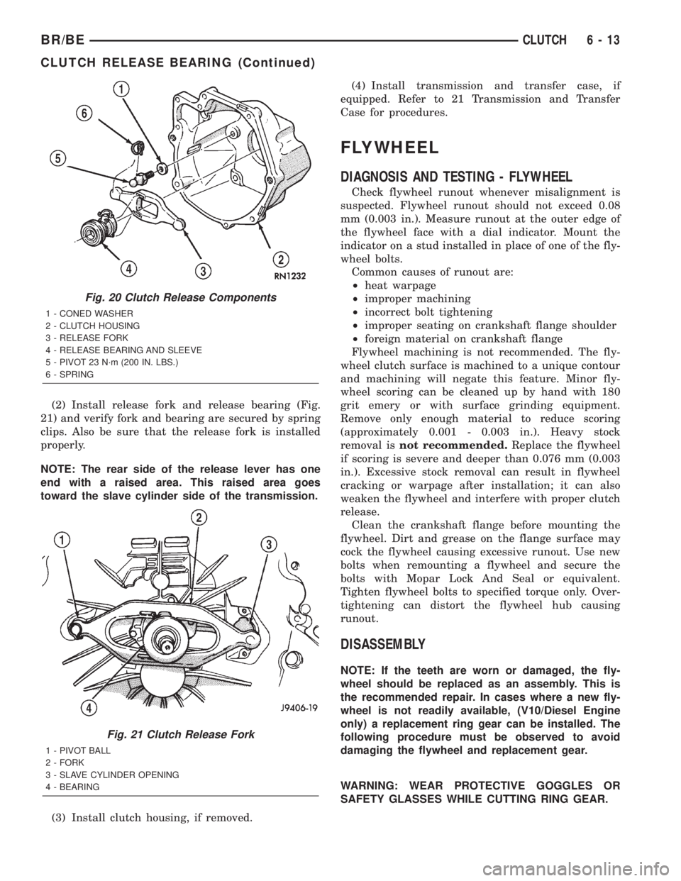
(2) Install release fork and release bearing (Fig.
21) and verify fork and bearing are secured by spring
clips. Also be sure that the release fork is installed
properly.
NOTE: The rear side of the release lever has one
end with a raised area. This raised area goes
toward the slave cylinder side of the transmission.
(3) Install clutch housing, if removed.(4) Install transmission and transfer case, if
equipped. Refer to 21 Transmission and Transfer
Case for procedures.
FLYWHEEL
DIAGNOSIS AND TESTING - FLYWHEEL
Check flywheel runout whenever misalignment is
suspected. Flywheel runout should not exceed 0.08
mm (0.003 in.). Measure runout at the outer edge of
the flywheel face with a dial indicator. Mount the
indicator on a stud installed in place of one of the fly-
wheel bolts.
Common causes of runout are:
²heat warpage
²improper machining
²incorrect bolt tightening
²improper seating on crankshaft flange shoulder
²foreign material on crankshaft flange
Flywheel machining is not recommended. The fly-
wheel clutch surface is machined to a unique contour
and machining will negate this feature. Minor fly-
wheel scoring can be cleaned up by hand with 180
grit emery or with surface grinding equipment.
Remove only enough material to reduce scoring
(approximately 0.001 - 0.003 in.). Heavy stock
removal isnot recommended.Replace the flywheel
if scoring is severe and deeper than 0.076 mm (0.003
in.). Excessive stock removal can result in flywheel
cracking or warpage after installation; it can also
weaken the flywheel and interfere with proper clutch
release.
Clean the crankshaft flange before mounting the
flywheel. Dirt and grease on the flange surface may
cock the flywheel causing excessive runout. Use new
bolts when remounting a flywheel and secure the
bolts with Mopar Lock And Seal or equivalent.
Tighten flywheel bolts to specified torque only. Over-
tightening can distort the flywheel hub causing
runout.
DISASSEMBLY
NOTE: If the teeth are worn or damaged, the fly-
wheel should be replaced as an assembly. This is
the recommended repair. In cases where a new fly-
wheel is not readily available, (V10/Diesel Engine
only) a replacement ring gear can be installed. The
following procedure must be observed to avoid
damaging the flywheel and replacement gear.
WARNING: WEAR PROTECTIVE GOGGLES OR
SAFETY GLASSES WHILE CUTTING RING GEAR.
Fig. 20 Clutch Release Components
1 - CONED WASHER
2 - CLUTCH HOUSING
3 - RELEASE FORK
4 - RELEASE BEARING AND SLEEVE
5 - PIVOT 23 N´m (200 IN. LBS.)
6 - SPRING
Fig. 21 Clutch Release Fork
1 - PIVOT BALL
2 - FORK
3 - SLAVE CYLINDER OPENING
4 - BEARING
BR/BECLUTCH 6 - 13
CLUTCH RELEASE BEARING (Continued)
Page 245 of 2255
(1) Mark position of the old gear for alignment ref-
erence on the flywheel. Use a scriber for this pur-
pose.
(2) Remove the old gear by cutting most of the way
through it (at one point) with an abrasive cut-off
wheel. Then complete removal with a cold chisel or
punch.
ASSEMBLY
NOTE: The ring gear is a shrink fit on the flywheel.
This means the gear must be expanded by heating
in order to install it. The method of heating and
expanding the gear is extremely important. Every
surface of the gear must be heated at the same
time to produce uniform expansion. An oven or
similar enclosed heating device must be used. Tem-
perature required for uniform expansion is approxi-
mately 375É F.
CAUTION: Do not use an oxy/acetylene torch to
remove the old gear, or to heat and expand a new
gear. The high temperature of the torch flame can
cause localized heating that will damage the fly-
wheel. In addition, using the torch to heat a replace-
ment gear will cause uneven heating and
expansion. The torch flame can also anneal the
gear teeth resulting in rapid wear and damage after
installation.
WARNING: WEAR PROTECTIVE GOGGLES OR
SAFETY GLASSES AND HEAT RESISTENT GLOVES
WHEN HANDLING A HEATED RING GEAR.
(1) The heated gear must be installed evenly to
avoid misalignment or distortion.
(2) Position and install the heated ring gear on the
flywheel with a shop press and a suitable press
plates.
(3) Place flywheel on work bench and let it cool in
normal shop air. Allow the ring gear to cool down
completely before installation it on the engine.
CAUTION: Do not use water or compressed air to
cool the flywheel. The rapid cooling produced by
water or compressed air will distort or crack the
new gear.
PILOT BEARING
REMOVAL
(1) Remove transmission, transfer case, if
equipped and clutch housing. Refer to 21 Transmis-
sion and Transfer Case for procedures.
(2) Remove pressure plate and disc.
(3) Using a suitable blind hole puller to remove
pilot bearing.
INSTALLATION
(1) Clean bearing bore with solvent and wipe dry
with shop towel.
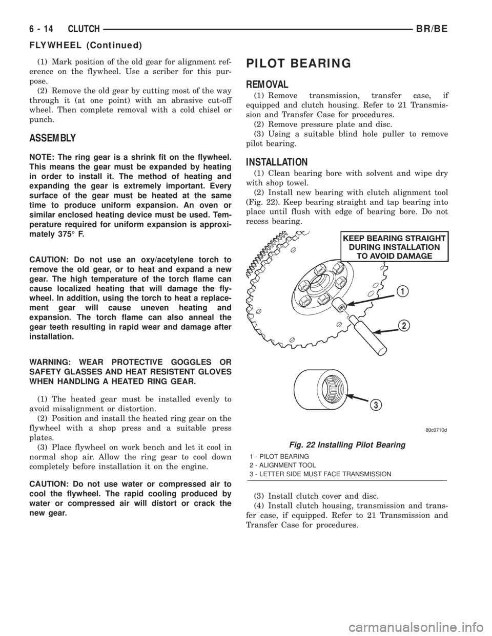
(2) Install new bearing with clutch alignment tool
(Fig. 22). Keep bearing straight and tap bearing into
place until flush with edge of bearing bore. Do not
recess bearing.
(3) Install clutch cover and disc.
(4) Install clutch housing, transmission and trans-
fer case, if equipped. Refer to 21 Transmission and
Transfer Case for procedures.
Fig. 22 Installing Pilot Bearing
1 - PILOT BEARING
2 - ALIGNMENT TOOL
3 - LETTER SIDE MUST FACE TRANSMISSION
6 - 14 CLUTCHBR/BE
FLYWHEEL (Continued)
Page 246 of 2255
CLUTCH PEDAL
REMOVAL
(1) Remove knee bolster for access to pedal pivot
shaft.
(2) Remove brake lamp switch.
(3) Remove retaining clips that secure the brake
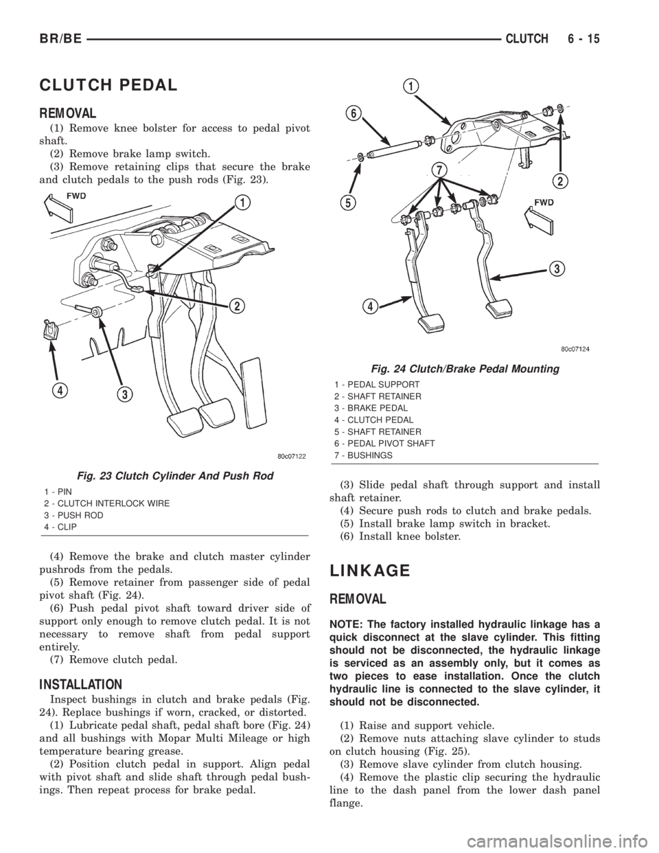
and clutch pedals to the push rods (Fig. 23).
(4) Remove the brake and clutch master cylinder
pushrods from the pedals.
(5) Remove retainer from passenger side of pedal
pivot shaft (Fig. 24).
(6) Push pedal pivot shaft toward driver side of
support only enough to remove clutch pedal. It is not
necessary to remove shaft from pedal support
entirely.
(7) Remove clutch pedal.
INSTALLATION
Inspect bushings in clutch and brake pedals (Fig.
24). Replace bushings if worn, cracked, or distorted.
(1) Lubricate pedal shaft, pedal shaft bore (Fig. 24)
and all bushings with Mopar Multi Mileage or high
temperature bearing grease.
(2) Position clutch pedal in support. Align pedal
with pivot shaft and slide shaft through pedal bush-
ings. Then repeat process for brake pedal.(3) Slide pedal shaft through support and install
shaft retainer.
(4) Secure push rods to clutch and brake pedals.
(5) Install brake lamp switch in bracket.
(6) Install knee bolster.
LINKAGE
REMOVAL
NOTE: The factory installed hydraulic linkage has a
quick disconnect at the slave cylinder. This fitting
should not be disconnected, the hydraulic linkage
is serviced as an assembly only, but it comes as
two pieces to ease installation. Once the clutch
hydraulic line is connected to the slave cylinder, it
should not be disconnected.
(1) Raise and support vehicle.
(2) Remove nuts attaching slave cylinder to studs
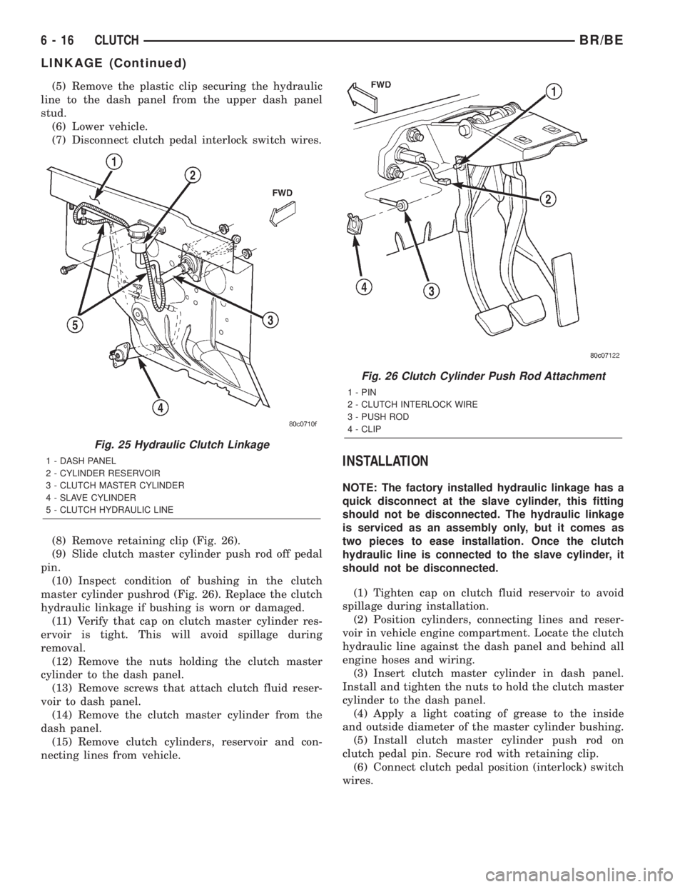
on clutch housing (Fig. 25).
(3) Remove slave cylinder from clutch housing.
(4) Remove the plastic clip securing the hydraulic
line to the dash panel from the lower dash panel
flange.
Fig. 23 Clutch Cylinder And Push Rod
1 - PIN
2 - CLUTCH INTERLOCK WIRE
3 - PUSH ROD
4 - CLIP
Fig. 24 Clutch/Brake Pedal Mounting
1 - PEDAL SUPPORT
2 - SHAFT RETAINER
3 - BRAKE PEDAL
4 - CLUTCH PEDAL
5 - SHAFT RETAINER
6 - PEDAL PIVOT SHAFT
7 - BUSHINGS
BR/BECLUTCH 6 - 15
Page 247 of 2255
(5) Remove the plastic clip securing the hydraulic
line to the dash panel from the upper dash panel
stud.
(6) Lower vehicle.
(7) Disconnect clutch pedal interlock switch wires.
(8) Remove retaining clip (Fig. 26).
(9) Slide clutch master cylinder push rod off pedal
pin.
(10) Inspect condition of bushing in the clutch
master cylinder pushrod (Fig. 26). Replace the clutch
hydraulic linkage if bushing is worn or damaged.
(11) Verify that cap on clutch master cylinder res-
ervoir is tight. This will avoid spillage during
removal.
(12) Remove the nuts holding the clutch master
cylinder to the dash panel.
(13) Remove screws that attach clutch fluid reser-
voir to dash panel.
(14) Remove the clutch master cylinder from the
dash panel.
(15) Remove clutch cylinders, reservoir and con-
necting lines from vehicle.
INSTALLATION
NOTE: The factory installed hydraulic linkage has a
quick disconnect at the slave cylinder, this fitting
should not be disconnected. The hydraulic linkage
is serviced as an assembly only, but it comes as
two pieces to ease installation. Once the clutch
hydraulic line is connected to the slave cylinder, it
should not be disconnected.
(1) Tighten cap on clutch fluid reservoir to avoid
spillage during installation.
(2) Position cylinders, connecting lines and reser-
voir in vehicle engine compartment. Locate the clutch
hydraulic line against the dash panel and behind all
engine hoses and wiring.
(3) Insert clutch master cylinder in dash panel.
Install and tighten the nuts to hold the clutch master
cylinder to the dash panel.
(4) Apply a light coating of grease to the inside
and outside diameter of the master cylinder bushing.
(5) Install clutch master cylinder push rod on
clutch pedal pin. Secure rod with retaining clip.
(6) Connect clutch pedal position (interlock) switch
wires.
Fig. 25 Hydraulic Clutch Linkage
1 - DASH PANEL
2 - CYLINDER RESERVOIR
3 - CLUTCH MASTER CYLINDER
4 - SLAVE CYLINDER
5 - CLUTCH HYDRAULIC LINE
Fig. 26 Clutch Cylinder Push Rod Attachment
1 - PIN
2 - CLUTCH INTERLOCK WIRE
3 - PUSH ROD
4 - CLIP
6 - 16 CLUTCHBR/BE
LINKAGE (Continued)
Page 248 of 2255
(7) Position clutch fluid reservoir on dash panel
and install reservoir screws. Tighten screws to 5 N´m
(40 in. lbs.).
(8) Install the plastic clip securing the hydraulic
line to the dash panel into the lower dash panel
flange.
(9) Install the plastic clip securing the hydraulic
line to the dash panel onto the upper dash panel
stud.
(10) Raise vehicle.
(11) Install slave cylinder. Be sure cap at end of
cylinder rod is seated in release lever. Check this
before installing cylinder attaching nuts.
NOTE: If new linkage is being installed, do not
remove the plastic shipping strap from slave cylin-
der push rod. The shipping strap will break on its
own upon the first clutch application.
(12) Install and tighten slave cylinder attaching
nuts to 23 N´m (200 in. lbs.).
(13) If a new clutch linkage is being installed, con-
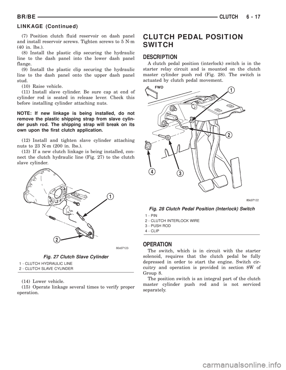
nect the clutch hydraulic line (Fig. 27) to the clutch
slave cylinder.
(14) Lower vehicle.
(15) Operate linkage several times to verify proper
operation.CLUTCH PEDAL POSITION
SWITCH
DESCRIPTION
A clutch pedal position (interlock) switch is in the
starter relay circuit and is mounted on the clutch
master cylinder push rod (Fig. 28). The switch is
actuated by clutch pedal movement.
OPERATION
The switch, which is in circuit with the starter
solenoid, requires that the clutch pedal be fully
depressed in order to start the engine. Switch cir-
cuitry and operation is provided in section 8W of
Group 8.
The position switch is an integral part of the clutch
master cylinder push rod and is not serviced
separately.
Fig. 27 Clutch Slave Cylinder
1 - CLUTCH HYDRAULIC LINE
2 - CLUTCH SLAVE CYLINDER
Fig. 28 Clutch Pedal Position (Interlock) Switch
1 - PIN
2 - CLUTCH INTERLOCK WIRE
3 - PUSH ROD
4 - CLIP
BR/BECLUTCH 6 - 17
LINKAGE (Continued)
Page 258 of 2255
CONDITION POSSIBLE CAUSES CORRECTION
8. Incorrect coolant concentration 8. Check coolant. (Refer to
LUBRICATION & MAINTENANCE/
FLUID TYPES - DESCRIPTION).
9. Coolant not flowing through
system9. Check for coolant flow at radiator
filler neck with some coolant
removed, engine warm and
thermostat open. Coolant should be
observed flowing through radiator. If
flow is not observed, determine area
of obstruction and repair as
necessary.
10. Radiator or A/C condenser fins
are dirty or clogged.10. Remove insects and debris.
(Refer to 7 - COOLING -
STANDARD PROCEDURE).
11. Radiator core is corroded or
plugged.11. Have radiator re-cored or
replaced.
12. Aftermarket A/C installed
without proper radiator.12. Install proper radiator.
13. Fuel or ignition system
problems.13. Refer to 14 - Fuel System or 8 -
Electrical for diagnosis and testing
procedures.
14. Dragging brakes. 14. Check and correct as
necessary. (Refer to 5 - BRAKES -
DIAGNOSIS AND TESTING) for
correct procedures.
15. Bug screen or cardboard is
being used, reducing airflow.15. Remove bug screen or
cardboard.
16. Thermostat partially or
completely shut.16. Check thermostat operation and
replace as necessary. (Refer to 7 -
COOLING/ENGINE/ENGINE
COOLANT THERMOSTAT -
REMOVAL).
17. Viscous fan drive not operating
properly.17. Check fan drive operation and
replace as necessary. (Refer to 7 -
COOLING/ENGINE/FAN DRIVE
VISCOUS CLUTCH - REMOVAL).
18. Cylinder head gasket leaking. 18. Check for cylinder head gasket
leaks. (Refer to 7 - COOLING -
DIAGNOSIS AND TESTING).
19. Heater core leaking. 19. Check heater core for leaks.
(Refer to 24 - HEATING & AIR
CONDITIONING/PLUMBING -
DIAGNOSIS AND TESTING).
Repair as necessary.
BR/BECOOLING 7 - 9
COOLING (Continued)
Page 260 of 2255

CONDITION POSSIBLE CAUSES CORRECTION
COOLANT LOSS TO THE
GROUND WITHOUT PRESSURE
CAP BLOWOFF. GAUGE READING
HIGH OR HOT1. Coolant leaks in radiator, cooling
system hoses, water pump or
engine.1. Pressure test and repair as
necessary. (Refer to 7 - COOLING -
DIAGNOSIS AND TESTING).
DETONATION OR PRE-IGNITION
(NOT CAUSED BY IGNITION
SYSTEM). GAUGE MAY OR MAY
NOT BE READING HIGH1. Engine overheating. 1. Check reason for overheating
and repair as necessary.
2. Freeze point of coolant not
correct. Mixture is too rich or too
lean.2. Check coolant concentration.
(Refer to LUBRICATION &
MAINTENANCE/FLUID TYPES -
DESCRIPTION).
HOSE OR HOSES COLLAPSE
WHILE ENGINE IS RUNNING1. Vacuum created in cooling
system on engine cool-down is not
being relieved through coolant
reserve/overflow system.1. (a) Radiator cap relief valve
stuck. (Refer to 7 - COOLING/
ENGINE/RADIATOR PRESSURE
CAP - DIAGNOSIS AND TESTING).
Replace if necessary
(b) Hose between coolant
reserve/overflow tank and radiator is
kinked. Repair as necessary.
(c) Vent at coolant reserve/overflow
tank is plugged. Clean vent and
repair as necessary.
(d) Reserve/overflow tank is
internally blocked or plugged. Check
for blockage and repair as
necessary.
NOISY VISCOUS FAN/DRIVE 1. Fan blades loose. 1. Replace fan blade assembly.
(Refer to 7 - COOLING/ENGINE/
RADIATOR FAN - REMOVAL)
2. Fan blades striking a surrounding
object.2. Locate point of fan blade contact
and repair as necessary.
3. Air obstructions at radiator or air
conditioning condenser.3. Remove obstructions and/or
clean debris or insects from radiator
or A/C condenser.
4. Thermal viscous fan drive has
defective bearing.4. Replace fan drive. Bearing is not
serviceable. (Refer to 7 - COOLING/
ENGINE/FAN DRIVE VISCOUS
CLUTCH - REMOVAL).
5. A certain amount of fan noise
may be evident on models
equipped with a thermal viscous fan
drive. Some of this noise is normal.5. (Refer to 7 - COOLING/ENGINE/
FAN DRIVE VISCOUS CLUTCH -
DESCRIPTION) for an explanation
of normal fan noise.
BR/BECOOLING 7 - 11
COOLING (Continued)
Page 262 of 2255

DIAGNOSIS AND TESTING - COOLING SYSTEM DIESEL ENGINE
COOLING SYSTEM DIAGNOSISÐDIESEL ENGINE
CONDITION POSSIBLE CAUSES CORRECTION
TEMPERATUREGAUGE READS
LOW1. Vehicle is equipped with a heavy
duty cooling system.1. None. System operating normaly.
2. Temperature gauge not
connected2. Connect gauge.
3. Temperature gauge connected
but not operating.3. Check gauge. Refer (Refer to 8 -
ELECTRICAL/INSTRUMENT
CLUSTER - DIAGNOSIS AND
TESTING)
4. Coolant level low. 4. Fill cooling system. (Refer to 7 -
COOLING - STANDARD
PROCEDURE)
TEMPERATURE GAUGE READS
HIGH. COOLANT MAY OR MAY
NOT BE LEAKING FROM SYSTEM1. Vehicle overloaded, high ambient
(outside) temperatures with A/C
turned on, stop and go driving or
prolonged operation at idle speeds.1. Temporary condition, repair not
required. Notify customer of vehicle
operation instructions located in
Owners Manual.
2. Temperature gauge not
functioning correctly.2. Check gauge. (Refer to 8 -
ELECTRICAL/INSTRUMENT
CLUSTER - DIAGNOSIS AND
TESTING)
3. Air traped in cooling 3. Drain cooling system (Refer to 7 -
COOLING - STANDARD
PROCEDURE) and refill (Refer to 7
- COOLING - STANDARD
PROCEDURE)
4. Radiator cap faulty. 4. Replace radiator cap.
5. Plugged A/C or radiator cooling
fins.5. Clean all debre away from A/C
and radiator cooling fins.
6. Coolant mixture incorrect. 6. Drain cooling system (Refer to 7 -
COOLING - STANDARD
PROCEDURE) refill with correct
mixture (Refer to 7 - COOLING -
STANDARD PROCEDURE).
7. Thermostat stuck shut. 7. Replace thermostat.
8. Bug screen or winter front being
used.8. Remove bug screen or winter
front.
9. Viscous fan drive not operating
properly.9. Check viscous fan (Refer to 7 -
COOLING/ENGINE/FAN DRIVE
VISCOUS CLUTCH - DIAGNOSIS
AND TESTING)
10. Cylinder head gasket leaking. 10. Check for leaking head gaskets
(Refer to 7 - COOLING -
DIAGNOSIS AND TESTING).
11. Heater core leaking. 11. Replace heater core.
12. cooling system hoses leaking. 12. Tighten clamps or Replace
hoses.
BR/BECOOLING 7 - 13
COOLING (Continued)