2002 DODGE RAM clutch
[x] Cancel search: clutchPage 236 of 2255
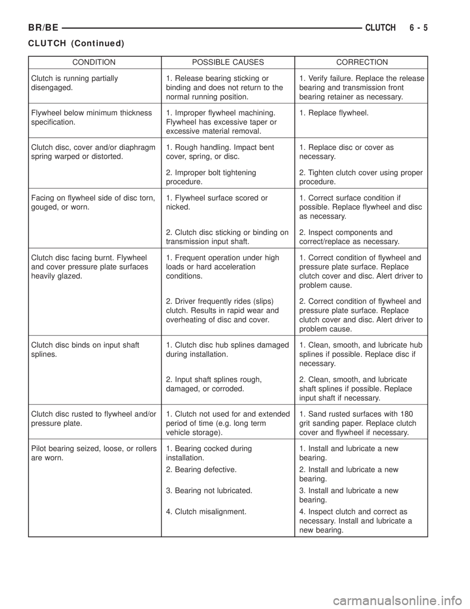
CONDITION POSSIBLE CAUSES CORRECTION
Clutch is running partially
disengaged.1. Release bearing sticking or
binding and does not return to the
normal running position.1. Verify failure. Replace the release
bearing and transmission front
bearing retainer as necessary.
Flywheel below minimum thickness
specification.1. Improper flywheel machining.
Flywheel has excessive taper or
excessive material removal.1. Replace flywheel.
Clutch disc, cover and/or diaphragm
spring warped or distorted.1. Rough handling. Impact bent
cover, spring, or disc.1. Replace disc or cover as
necessary.
2. Improper bolt tightening
procedure.2. Tighten clutch cover using proper
procedure.
Facing on flywheel side of disc torn,
gouged, or worn.1. Flywheel surface scored or
nicked.1. Correct surface condition if
possible. Replace flywheel and disc
as necessary.
2. Clutch disc sticking or binding on
transmission input shaft.2. Inspect components and
correct/replace as necessary.
Clutch disc facing burnt. Flywheel
and cover pressure plate surfaces
heavily glazed.1. Frequent operation under high
loads or hard acceleration
conditions.1. Correct condition of flywheel and
pressure plate surface. Replace
clutch cover and disc. Alert driver to
problem cause.
2. Driver frequently rides (slips)
clutch. Results in rapid wear and
overheating of disc and cover.2. Correct condition of flywheel and
pressure plate surface. Replace
clutch cover and disc. Alert driver to
problem cause.
Clutch disc binds on input shaft
splines.1. Clutch disc hub splines damaged
during installation.1. Clean, smooth, and lubricate hub
splines if possible. Replace disc if
necessary.
2. Input shaft splines rough,
damaged, or corroded.2. Clean, smooth, and lubricate
shaft splines if possible. Replace
input shaft if necessary.
Clutch disc rusted to flywheel and/or
pressure plate.1. Clutch not used for and extended
period of time (e.g. long term
vehicle storage).1. Sand rusted surfaces with 180
grit sanding paper. Replace clutch
cover and flywheel if necessary.
Pilot bearing seized, loose, or rollers
are worn.1. Bearing cocked during
installation.1. Install and lubricate a new
bearing.
2. Bearing defective. 2. Install and lubricate a new
bearing.
3. Bearing not lubricated. 3. Install and lubricate a new
bearing.
4. Clutch misalignment. 4. Inspect clutch and correct as
necessary. Install and lubricate a
new bearing.
BR/BECLUTCH 6 - 5
CLUTCH (Continued)
Page 237 of 2255
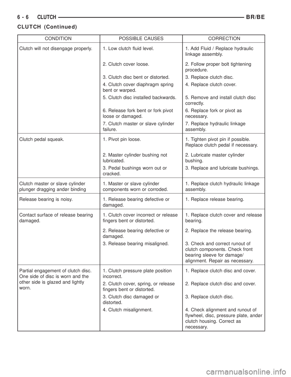
CONDITION POSSIBLE CAUSES CORRECTION
Clutch will not disengage properly. 1. Low clutch fluid level. 1. Add Fluid / Replace hydraulic
linkage assembly.
2. Clutch cover loose. 2. Follow proper bolt tightening
procedure.
3. Clutch disc bent or distorted. 3. Replace clutch disc.
4. Clutch cover diaphragm spring
bent or warped.4. Replace clutch cover.
5. Clutch disc installed backwards. 5. Remove and install clutch disc
correctly.
6. Release fork bent or fork pivot
loose or damaged.6. Replace fork or pivot as
necessary.
7. Clutch master or slave cylinder
failure.7. Replace hydraulic linkage
assembly.
Clutch pedal squeak. 1. Pivot pin loose. 1. Tighten pivot pin if possible.
Replace clutch pedal if necessary.
2. Master cylinder bushing not
lubricated.2. Lubricate master cylinder
bushing.
3. Pedal bushings worn out or
cracked.3. Replace and lubricate bushings.
Clutch master or slave cylinder
plunger dragging andùr binding1. Master or slave cylinder
components worn or corroded.1. Replace clutch hydraulic linkage
assembly.
Release bearing is noisy. 1. Release bearing defective or
damaged.1. Replace release bearing.
Contact surface of release bearing
damaged.1. Clutch cover incorrect or release
fingers bent or distorted.1. Replace clutch cover and release
bearing.
2. Release bearing defective or
damaged.2. Replace the release bearing.
3. Release bearing misaligned. 3. Check and correct runout of
clutch components. Check front
bearing sleeve for damage/
alignment. Repair as necessary.
Partial engagement of clutch disc.
One side of disc is worn and the
other side is glazed and lightly
worn.1. Clutch pressure plate position
incorrect.1. Replace clutch disc and cover.
2. Clutch cover, spring, or release
fingers bent or distorted.2. Replace clutch disc and cover.
3. Clutch disc damaged or
distorted.3. Replace clutch disc.
4. Clutch misalignment. 4. Check alignment and runout of
flywheel, disc, pressure plate, andùr
clutch housing. Correct as
necessary.
6 - 6 CLUTCHBR/BE
CLUTCH (Continued)
Page 238 of 2255
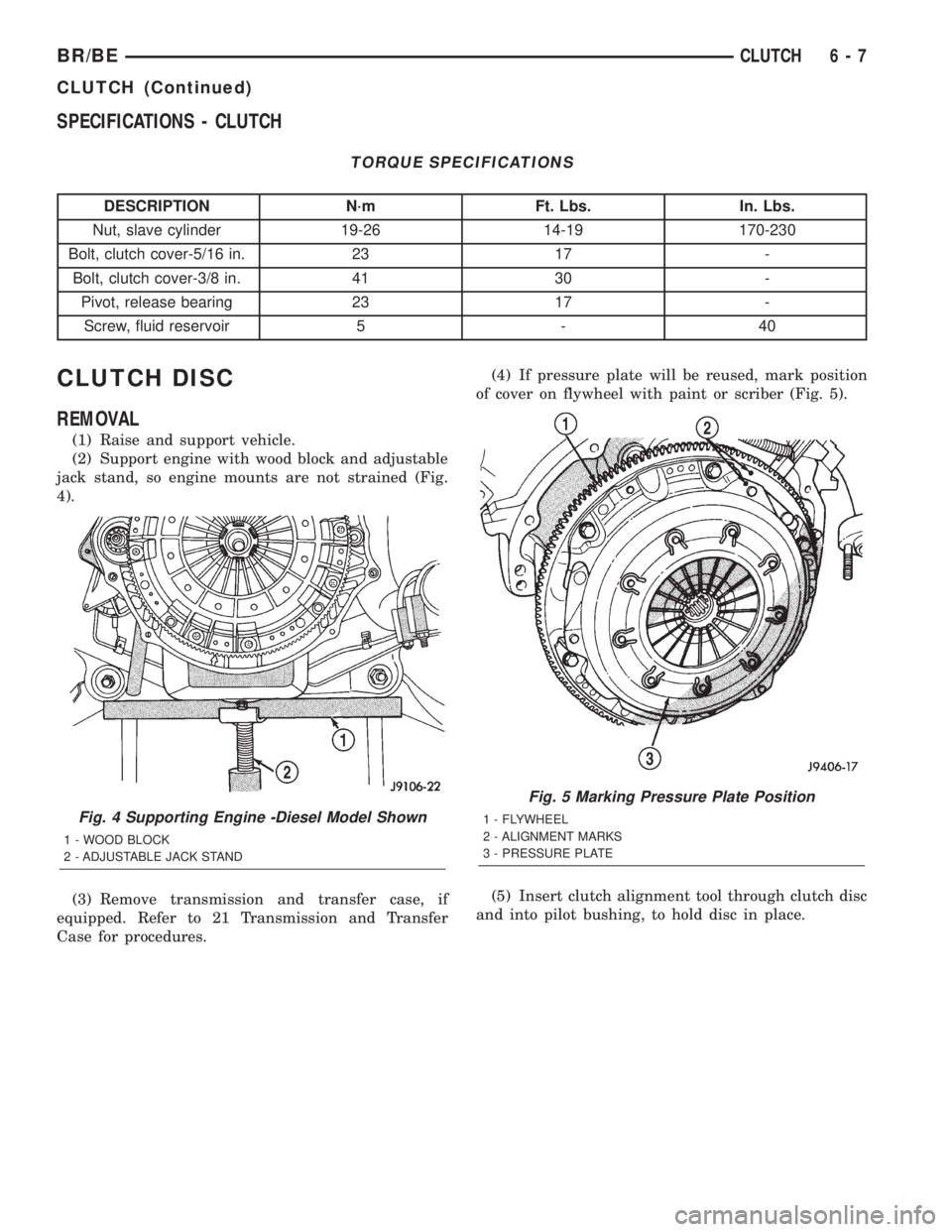
SPECIFICATIONS - CLUTCH
TORQUE SPECIFICATIONS
DESCRIPTION N´m Ft. Lbs. In. Lbs.
Nut, slave cylinder 19-26 14-19 170-230
Bolt, clutch cover-5/16 in. 23 17 -
Bolt, clutch cover-3/8 in. 41 30 -
Pivot, release bearing 23 17 -
Screw, fluid reservoir 5 - 40
CLUTCH DISC
REMOVAL
(1) Raise and support vehicle.
(2) Support engine with wood block and adjustable
jack stand, so engine mounts are not strained (Fig.
4).
(3) Remove transmission and transfer case, if
equipped. Refer to 21 Transmission and Transfer
Case for procedures.(4) If pressure plate will be reused, mark position
of cover on flywheel with paint or scriber (Fig. 5).
(5) Insert clutch alignment tool through clutch disc
and into pilot bushing, to hold disc in place.
Fig. 4 Supporting Engine -Diesel Model Shown
1 - WOOD BLOCK
2 - ADJUSTABLE JACK STAND
Fig. 5 Marking Pressure Plate Position
1 - FLYWHEEL
2 - ALIGNMENT MARKS
3 - PRESSURE PLATE
BR/BECLUTCH 6 - 7
CLUTCH (Continued)
Page 239 of 2255

(6) If pressure plate will be reused, loosen cover
bolts evenly only few threads at a time in a diagonal
pattern (Fig. 6). This relieves cover spring tension
evenly to avoid warping.
(7) Remove bolts completely and remove plate, disc
and alignment tool.
INSTALLATION
(1) Check runout and free operation of new clutch
disc.
(2) Insert clutch alignment tool in pressure plate
and clutch disc.
(3) Insert alignment tool in pilot bearing and posi-
tion plate and disc on flywheel (Fig. 7).
NOTE: Raised side of disc hub faces away from the
flywheel.
(4) Iinstall cover bolts finger tight.
(5) Tighten cover bolts evenly and a few threads at
a time.
CAUTION: Cover bolts must be tightened evenly to
avoid distorting cover.
(6) Tighten clutch cover bolts to:
²5/16 in. diameter bolts to 23 N´m (17 ft. lbs.).
²3/8 in. diameter bolts to 41 N´m (30 ft. lbs.).(7) Remove release lever and release bearing from
clutch housing. Apply Mopar high temperature bear-
ing grease or equivalent to bore of release bearing,
release lever contact surfaces and release lever pivot
stud (Fig. 8).
(8) Apply light coat of Mopar high temperature
bearing grease or equivalent to splines of transmis-
sion input shaft (or drive gear) and to release bearing
slide surface of the transmission front bearing
retainer (Fig. 9).
CAUTION: Do not over lubricate shaft splines. This
can result in grease contamination of disc.
(9) Install release lever and bearing in clutch
housing. Be sure spring clips that retain fork on
pivot ball and release bearing on fork are secure (Fig.
10). Also verify that the release lever is installed
properly.
NOTE: Release lever is installed correctly, when
lever part number is toward the bottom of the trans-
mission. Also a stamped ªIº in the lever goes
towards the pivot ball side of the transmission.
(10) Install transmission. Refer to 21 Transmission
and Transfer Case for procedures.
(11) Check fluid level in clutch master cylinder.
Fig. 6 Bolt Loosening/Tightening Pattern
Fig. 7 Pressure Plate And Disc Alignment
1 - FLYWHEEL
2 - PRESSURE PLATE AND DISC
3 - CLUTCH DISC ALIGNMENT TOOL
6 - 8 CLUTCHBR/BE
CLUTCH DISC (Continued)
Page 240 of 2255
CLUTCH HOUSING
DIAGNOSIS AND TESTING - CLUTCH HOUSING
The clutch housing maintains alignment between
the crankshaft and transmission input shaft. Mis-
alignment can cause clutch noise, hard shifting,
incomplete release and chatter. Also premature pilot
bearing, cover release fingers and clutch disc wear.
In severe cases, it can cause premature wear of the
transmission input shaft and front bearing.
NOTE: Only the NV4500 clutch housing can be
checked using the following bore and face runout
procedures. The NV5600 clutch housing is a inte-
gral part of the transmission and can only be
checked off the vehicle.
CLUTCH HOUSING BORE RUNOUT
CAUTION: On diesel engines if housing bore runout
exceeds 0.015 inch, the clutch housing/transmis-
sion adapter plate must be replaced. On gas
engines if housing bore runout exceeds 0.053 in.
the clutch housing must be replaced.
NOTE: Offset dowels are available for gas engines
to correct housing bore runout. They are not avail-
able for diesel engines.
(1) Remove the clutch housing and strut.
(2) Remove the clutch cover and disc.
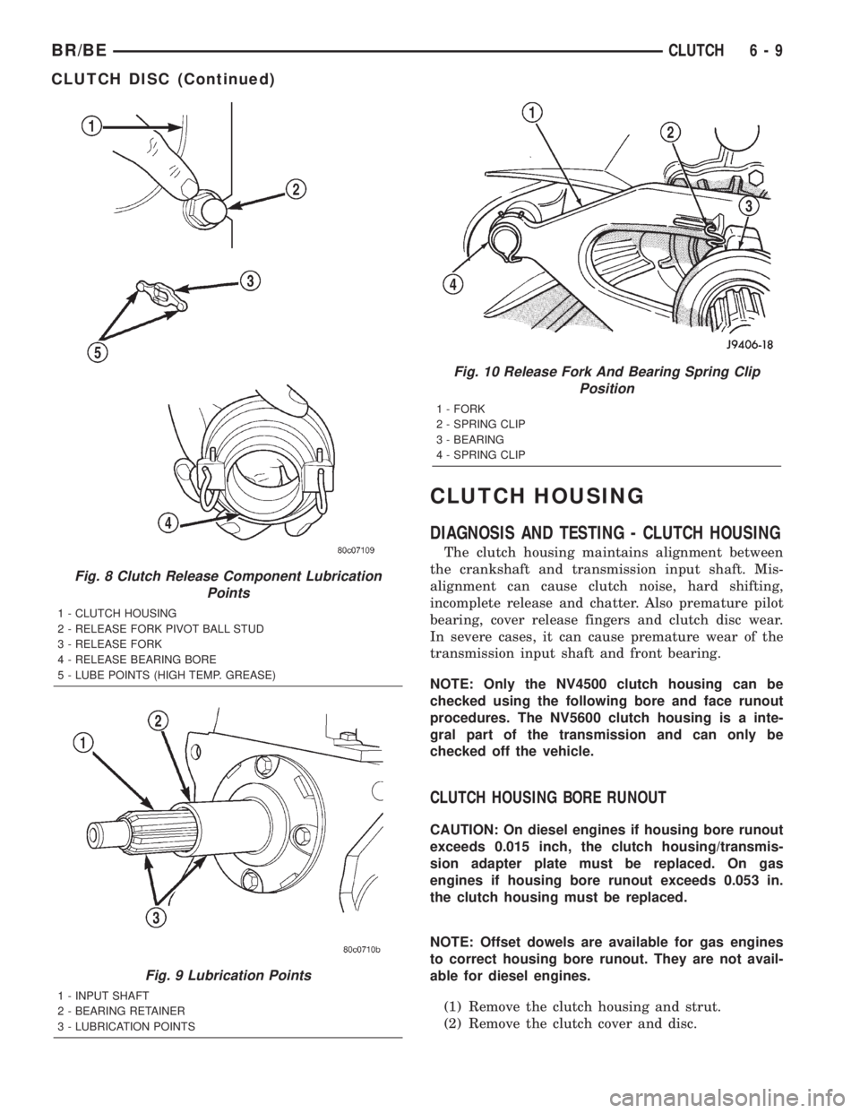
Fig. 8 Clutch Release Component Lubrication
Points
1 - CLUTCH HOUSING
2 - RELEASE FORK PIVOT BALL STUD
3 - RELEASE FORK
4 - RELEASE BEARING BORE
5 - LUBE POINTS (HIGH TEMP. GREASE)
Fig. 9 Lubrication Points
1 - INPUT SHAFT
2 - BEARING RETAINER
3 - LUBRICATION POINTS
Fig. 10 Release Fork And Bearing Spring Clip
Position
1 - FORK
2 - SPRING CLIP
3 - BEARING
4 - SPRING CLIP
BR/BECLUTCH 6 - 9
CLUTCH DISC (Continued)
Page 241 of 2255
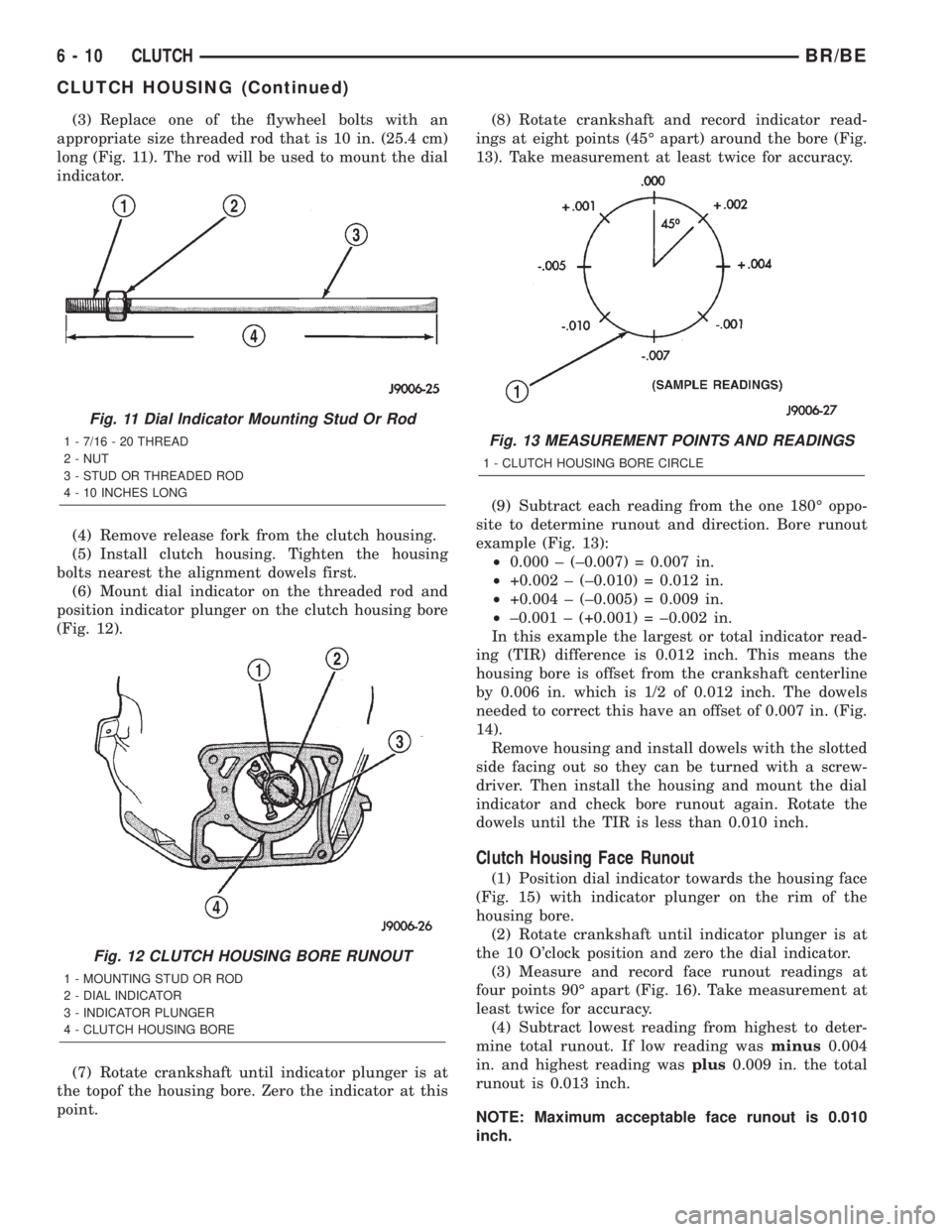
(3) Replace one of the flywheel bolts with an
appropriate size threaded rod that is 10 in. (25.4 cm)
long (Fig. 11). The rod will be used to mount the dial
indicator.
(4) Remove release fork from the clutch housing.
(5) Install clutch housing. Tighten the housing
bolts nearest the alignment dowels first.
(6) Mount dial indicator on the threaded rod and
position indicator plunger on the clutch housing bore
(Fig. 12).
(7) Rotate crankshaft until indicator plunger is at
the topof the housing bore. Zero the indicator at this
point.(8) Rotate crankshaft and record indicator read-
ings at eight points (45É apart) around the bore (Fig.
13). Take measurement at least twice for accuracy.
(9) Subtract each reading from the one 180É oppo-
site to determine runout and direction. Bore runout
example (Fig. 13):
²0.000 ± (±0.007) = 0.007 in.
²+0.002 ± (±0.010) = 0.012 in.
²+0.004 ± (±0.005) = 0.009 in.
²±0.001 ± (+0.001) = ±0.002 in.
In this example the largest or total indicator read-
ing (TIR) difference is 0.012 inch. This means the
housing bore is offset from the crankshaft centerline
by 0.006 in. which is 1/2 of 0.012 inch. The dowels
needed to correct this have an offset of 0.007 in. (Fig.
14).
Remove housing and install dowels with the slotted
side facing out so they can be turned with a screw-
driver. Then install the housing and mount the dial
indicator and check bore runout again. Rotate the
dowels until the TIR is less than 0.010 inch.
Clutch Housing Face Runout
(1) Position dial indicator towards the housing face
(Fig. 15) with indicator plunger on the rim of the
housing bore.
(2) Rotate crankshaft until indicator plunger is at
the 10 O'clock position and zero the dial indicator.
(3) Measure and record face runout readings at
four points 90É apart (Fig. 16). Take measurement at
least twice for accuracy.
(4) Subtract lowest reading from highest to deter-
mine total runout. If low reading wasminus0.004
in. and highest reading wasplus0.009 in. the total
runout is 0.013 inch.
NOTE: Maximum acceptable face runout is 0.010
inch.
Fig. 11 Dial Indicator Mounting Stud Or Rod
1 - 7/16 - 20 THREAD
2 - NUT
3 - STUD OR THREADED ROD
4 - 10 INCHES LONG
Fig. 12 CLUTCH HOUSING BORE RUNOUT
1 - MOUNTING STUD OR ROD
2 - DIAL INDICATOR
3 - INDICATOR PLUNGER
4 - CLUTCH HOUSING BORE
Fig. 13 MEASUREMENT POINTS AND READINGS
1 - CLUTCH HOUSING BORE CIRCLE
6 - 10 CLUTCHBR/BE
CLUTCH HOUSING (Continued)
Page 242 of 2255
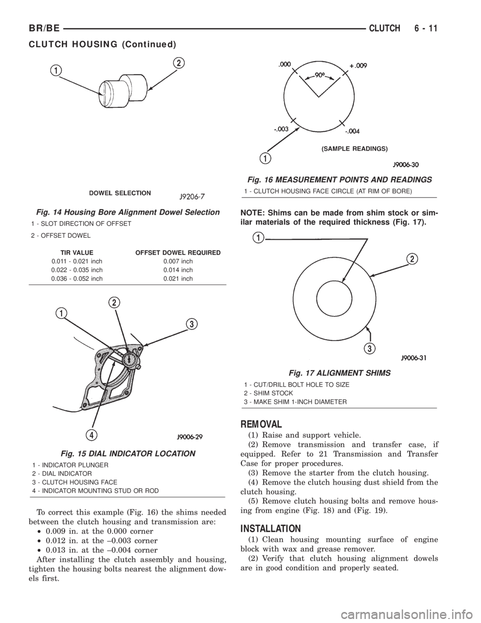
To correct this example (Fig. 16) the shims needed
between the clutch housing and transmission are:
²0.009 in. at the 0.000 corner
²0.012 in. at the ±0.003 corner
²0.013 in. at the ±0.004 corner
After installing the clutch assembly and housing,
tighten the housing bolts nearest the alignment dow-
els first.NOTE: Shims can be made from shim stock or sim-
ilar materials of the required thickness (Fig. 17).
REMOVAL
(1) Raise and support vehicle.
(2) Remove transmission and transfer case, if
equipped. Refer to 21 Transmission and Transfer
Case for proper procedures.
(3) Remove the starter from the clutch housing.
(4) Remove the clutch housing dust shield from the
clutch housing.
(5) Remove clutch housing bolts and remove hous-
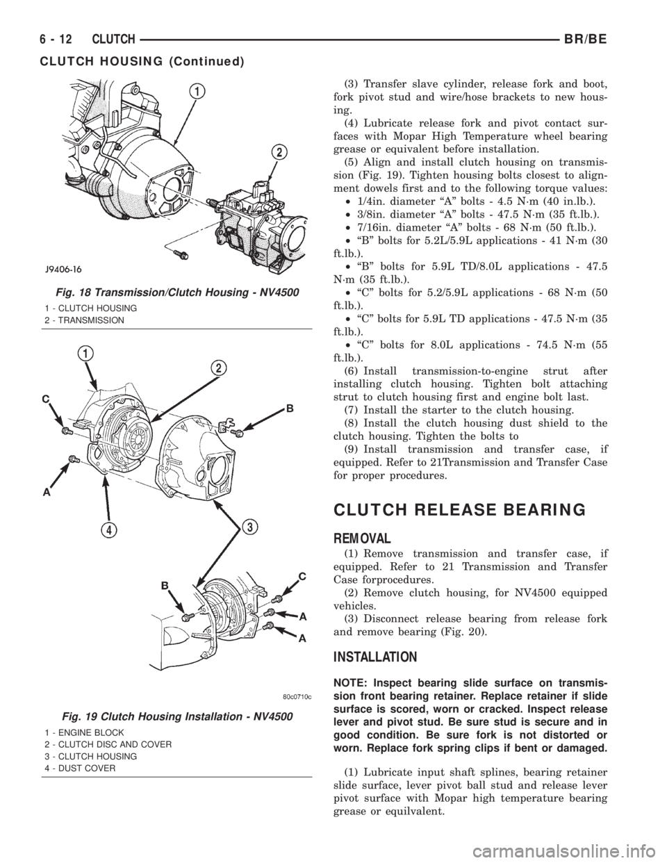
ing from engine (Fig. 18) and (Fig. 19).
INSTALLATION
(1) Clean housing mounting surface of engine
block with wax and grease remover.
(2) Verify that clutch housing alignment dowels
are in good condition and properly seated.
Fig. 14 Housing Bore Alignment Dowel Selection
1 - SLOT DIRECTION OF OFFSET
2 - OFFSET DOWEL
TIR VALUE OFFSET DOWEL REQUIRED
0.011 - 0.021 inch 0.007 inch
0.022 - 0.035 inch 0.014 inch
0.036 - 0.052 inch 0.021 inch
Fig. 15 DIAL INDICATOR LOCATION
1 - INDICATOR PLUNGER
2 - DIAL INDICATOR
3 - CLUTCH HOUSING FACE
4 - INDICATOR MOUNTING STUD OR ROD
Fig. 16 MEASUREMENT POINTS AND READINGS
1 - CLUTCH HOUSING FACE CIRCLE (AT RIM OF BORE)
Fig. 17 ALIGNMENT SHIMS
1 - CUT/DRILL BOLT HOLE TO SIZE
2 - SHIM STOCK
3 - MAKE SHIM 1-INCH DIAMETER
BR/BECLUTCH 6 - 11
CLUTCH HOUSING (Continued)
Page 243 of 2255
(3) Transfer slave cylinder, release fork and boot,
fork pivot stud and wire/hose brackets to new hous-
ing.
(4) Lubricate release fork and pivot contact sur-
faces with Mopar High Temperature wheel bearing
grease or equivalent before installation.
(5) Align and install clutch housing on transmis-
sion (Fig. 19). Tighten housing bolts closest to align-
ment dowels first and to the following torque values:
²1/4in. diameter ªAº bolts - 4.5 N´m (40 in.lb.).
²3/8in. diameter ªAº bolts - 47.5 N´m (35 ft.lb.).
²7/16in. diameter ªAº bolts - 68 N´m (50 ft.lb.).
²ªBº bolts for 5.2L/5.9L applications - 41 N´m (30
ft.lb.).
²ªBº bolts for 5.9L TD/8.0L applications - 47.5
N´m (35 ft.lb.).
²ªCº bolts for 5.2/5.9L applications - 68 N´m (50
ft.lb.).
²ªCº bolts for 5.9L TD applications - 47.5 N´m (35
ft.lb.).
²ªCº bolts for 8.0L applications - 74.5 N´m (55
ft.lb.).
(6) Install transmission-to-engine strut after
installing clutch housing. Tighten bolt attaching
strut to clutch housing first and engine bolt last.
(7) Install the starter to the clutch housing.
(8) Install the clutch housing dust shield to the
clutch housing. Tighten the bolts to
(9) Install transmission and transfer case, if
equipped. Refer to 21Transmission and Transfer Case
for proper procedures.
CLUTCH RELEASE BEARING
REMOVAL
(1) Remove transmission and transfer case, if
equipped. Refer to 21 Transmission and Transfer
Case forprocedures.
(2) Remove clutch housing, for NV4500 equipped
vehicles.
(3) Disconnect release bearing from release fork
and remove bearing (Fig. 20).
INSTALLATION
NOTE: Inspect bearing slide surface on transmis-
sion front bearing retainer. Replace retainer if slide
surface is scored, worn or cracked. Inspect release
lever and pivot stud. Be sure stud is secure and in
good condition. Be sure fork is not distorted or
worn. Replace fork spring clips if bent or damaged.
(1) Lubricate input shaft splines, bearing retainer
slide surface, lever pivot ball stud and release lever
pivot surface with Mopar high temperature bearing
grease or equilvalent.
Fig. 18 Transmission/Clutch Housing - NV4500
1 - CLUTCH HOUSING
2 - TRANSMISSION
Fig. 19 Clutch Housing Installation - NV4500
1 - ENGINE BLOCK
2 - CLUTCH DISC AND COVER
3 - CLUTCH HOUSING
4 - DUST COVER
6 - 12 CLUTCHBR/BE
CLUTCH HOUSING (Continued)