2002 DODGE RAM lock
[x] Cancel search: lockPage 1941 of 2255
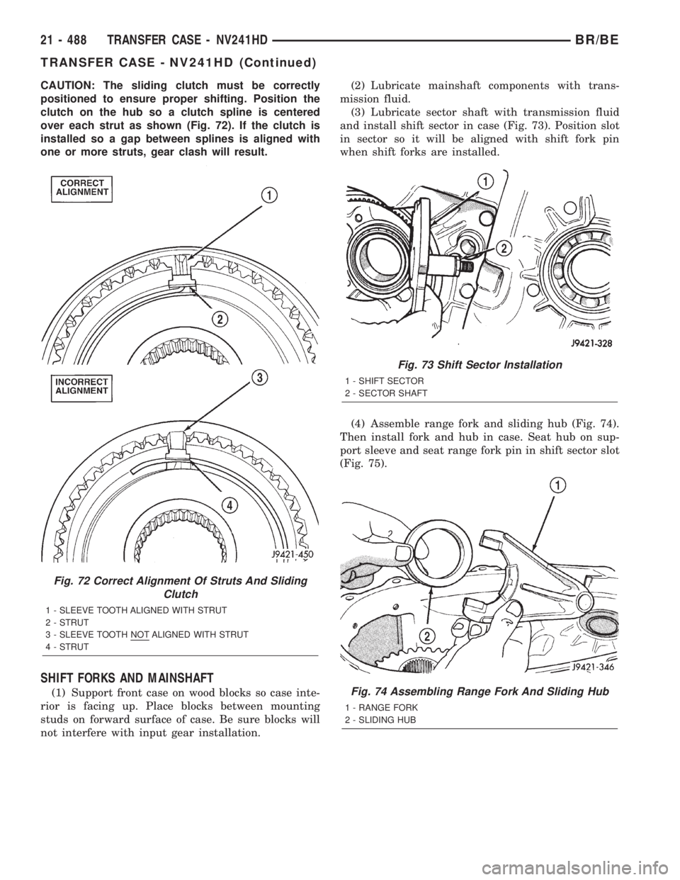
CAUTION: The sliding clutch must be correctly
positioned to ensure proper shifting. Position the
clutch on the hub so a clutch spline is centered
over each strut as shown (Fig. 72). If the clutch is
installed so a gap between splines is aligned with
one or more struts, gear clash will result.
SHIFT FORKS AND MAINSHAFT
(1) Support front case on wood blocks so case inte-
rior is facing up. Place blocks between mounting
studs on forward surface of case. Be sure blocks will
not interfere with input gear installation.(2) Lubricate mainshaft components with trans-
mission fluid.
(3) Lubricate sector shaft with transmission fluid
and install shift sector in case (Fig. 73). Position slot
in sector so it will be aligned with shift fork pin
when shift forks are installed.
(4) Assemble range fork and sliding hub (Fig. 74).
Then install fork and hub in case. Seat hub on sup-
port sleeve and seat range fork pin in shift sector slot
(Fig. 75).
Fig. 72 Correct Alignment Of Struts And Sliding
Clutch
1 - SLEEVE TOOTH ALIGNED WITH STRUT
2 - STRUT
3 - SLEEVE TOOTH NOT ALIGNED WITH STRUT
4 - STRUT
Fig. 73 Shift Sector Installation
1 - SHIFT SECTOR
2 - SECTOR SHAFT
Fig. 74 Assembling Range Fork And Sliding Hub
1 - RANGE FORK
2 - SLIDING HUB
21 - 488 TRANSFER CASE - NV241HDBR/BE
TRANSFER CASE - NV241HD (Continued)
Page 1943 of 2255
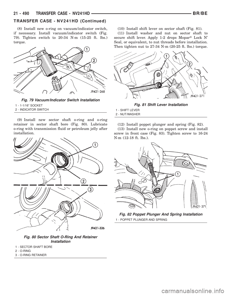
(8) Install new o-ring on vacuum/indicator switch,
if necessary. Install vacuum/indicator switch (Fig.
79). Tighten switch to 20-34 N´m (15-25 ft. lbs.)
torque.
(9) Install new sector shaft o-ring and o-ring
retainer in sector shaft bore (Fig. 80). Lubricate
o-ring with transmission fluid or petroleum jelly after
installation.(10) Install shift lever on sector shaft (Fig. 81).
(11) Install washer and nut on sector shaft to
secure shift lever. Apply 1-2 drops MopartLock N'
Seal, or equivalent, to nut threads before installation.
Then tighten nut to 27-34 N´m (20-25 ft. lbs.) torque.
(12) Install poppet plunger and spring (Fig. 82).
(13) Install new o-ring on poppet screw and install
screw in front case (Fig. 83). Tighten screw to 16-24
N´m (12-18 ft. lbs.).
Fig. 79 Vacuum/Indicator Switch Installation
1 - 1-1/16º SOCKET
2 - INDICATOR SWITCH
Fig. 80 Sector Shaft O-Ring And Retainer
Installation
1 - SECTOR SHAFT BORE
2 - O-RING
3 - O-RING RETAINER
Fig. 81 Shift Lever Installation
1 - SHIFT LEVER
2 - NUT/WASHER
Fig. 82 Poppet Plunger And Spring Installation
1 - POPPET PLUNGER AND SPRING
21 - 490 TRANSFER CASE - NV241HDBR/BE
TRANSFER CASE - NV241HD (Continued)
Page 1946 of 2255
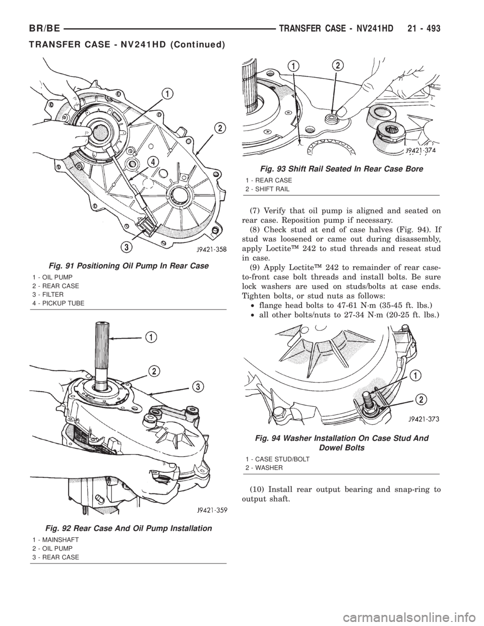
(7) Verify that oil pump is aligned and seated on
rear case. Reposition pump if necessary.
(8) Check stud at end of case halves (Fig. 94). If
stud was loosened or came out during disassembly,
apply LoctiteŸ 242 to stud threads and reseat stud
in case.
(9) Apply LoctiteŸ 242 to remainder of rear case-
to-front case bolt threads and install bolts. Be sure
lock washers are used on studs/bolts at case ends.
Tighten bolts, or stud nuts as follows:
²flange head bolts to 47-61 N´m (35-45 ft. lbs.)
²all other bolts/nuts to 27-34 N´m (20-25 ft. lbs.)
(10) Install rear output bearing and snap-ring to
output shaft.
Fig. 91 Positioning Oil Pump In Rear Case
1 - OIL PUMP
2 - REAR CASE
3 - FILTER
4 - PICKUP TUBE
Fig. 92 Rear Case And Oil Pump Installation
1 - MAINSHAFT
2 - OIL PUMP
3 - REAR CASE
Fig. 93 Shift Rail Seated In Rear Case Bore
1 - REAR CASE
2 - SHIFT RAIL
Fig. 94 Washer Installation On Case Stud And
Dowel Bolts
1 - CASE STUD/BOLT
2 - WASHER
BR/BETRANSFER CASE - NV241HD 21 - 493
TRANSFER CASE - NV241HD (Continued)
Page 1947 of 2255
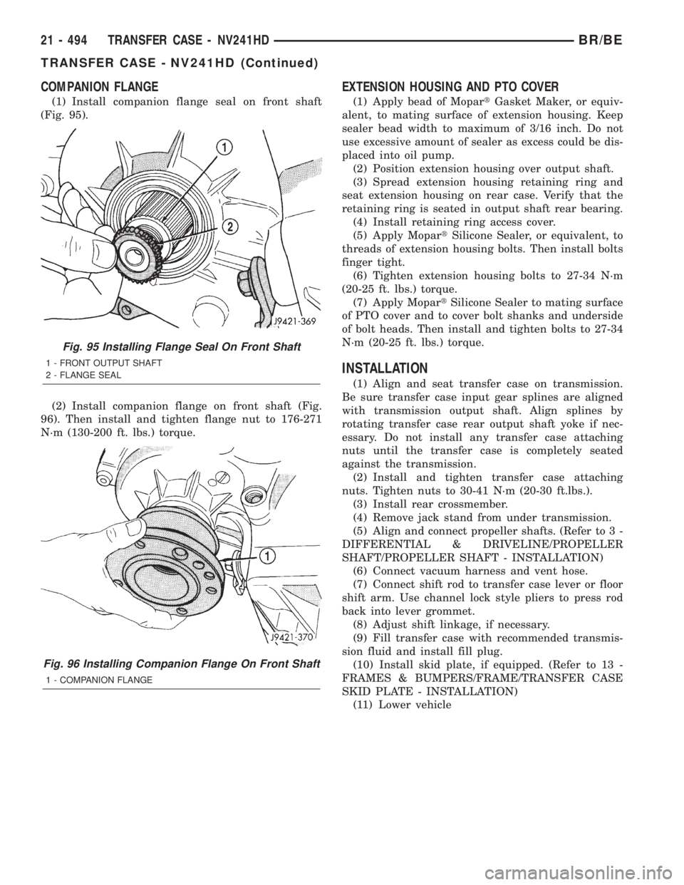
COMPANION FLANGE
(1) Install companion flange seal on front shaft
(Fig. 95).
(2) Install companion flange on front shaft (Fig.
96). Then install and tighten flange nut to 176-271
N´m (130-200 ft. lbs.) torque.
EXTENSION HOUSING AND PTO COVER
(1) Apply bead of MopartGasket Maker, or equiv-
alent, to mating surface of extension housing. Keep
sealer bead width to maximum of 3/16 inch. Do not
use excessive amount of sealer as excess could be dis-
placed into oil pump.
(2) Position extension housing over output shaft.
(3) Spread extension housing retaining ring and
seat extension housing on rear case. Verify that the
retaining ring is seated in output shaft rear bearing.
(4) Install retaining ring access cover.
(5) Apply MopartSilicone Sealer, or equivalent, to
threads of extension housing bolts. Then install bolts
finger tight.
(6) Tighten extension housing bolts to 27-34 N´m
(20-25 ft. lbs.) torque.
(7) Apply MopartSilicone Sealer to mating surface
of PTO cover and to cover bolt shanks and underside
of bolt heads. Then install and tighten bolts to 27-34
N´m (20-25 ft. lbs.) torque.
INSTALLATION
(1) Align and seat transfer case on transmission.
Be sure transfer case input gear splines are aligned
with transmission output shaft. Align splines by
rotating transfer case rear output shaft yoke if nec-
essary. Do not install any transfer case attaching
nuts until the transfer case is completely seated
against the transmission.
(2) Install and tighten transfer case attaching
nuts. Tighten nuts to 30-41 N´m (20-30 ft.lbs.).
(3) Install rear crossmember.
(4) Remove jack stand from under transmission.
(5) Align and connect propeller shafts. (Refer to 3 -
DIFFERENTIAL & DRIVELINE/PROPELLER
SHAFT/PROPELLER SHAFT - INSTALLATION)
(6) Connect vacuum harness and vent hose.
(7) Connect shift rod to transfer case lever or floor
shift arm. Use channel lock style pliers to press rod
back into lever grommet.
(8) Adjust shift linkage, if necessary.
(9) Fill transfer case with recommended transmis-
sion fluid and install fill plug.
(10) Install skid plate, if equipped. (Refer to 13 -
FRAMES & BUMPERS/FRAME/TRANSFER CASE
SKID PLATE - INSTALLATION)
(11) Lower vehicle
Fig. 95 Installing Flange Seal On Front Shaft
1 - FRONT OUTPUT SHAFT
2 - FLANGE SEAL
Fig. 96 Installing Companion Flange On Front Shaft
1 - COMPANION FLANGE
21 - 494 TRANSFER CASE - NV241HDBR/BE
TRANSFER CASE - NV241HD (Continued)
Page 1952 of 2255
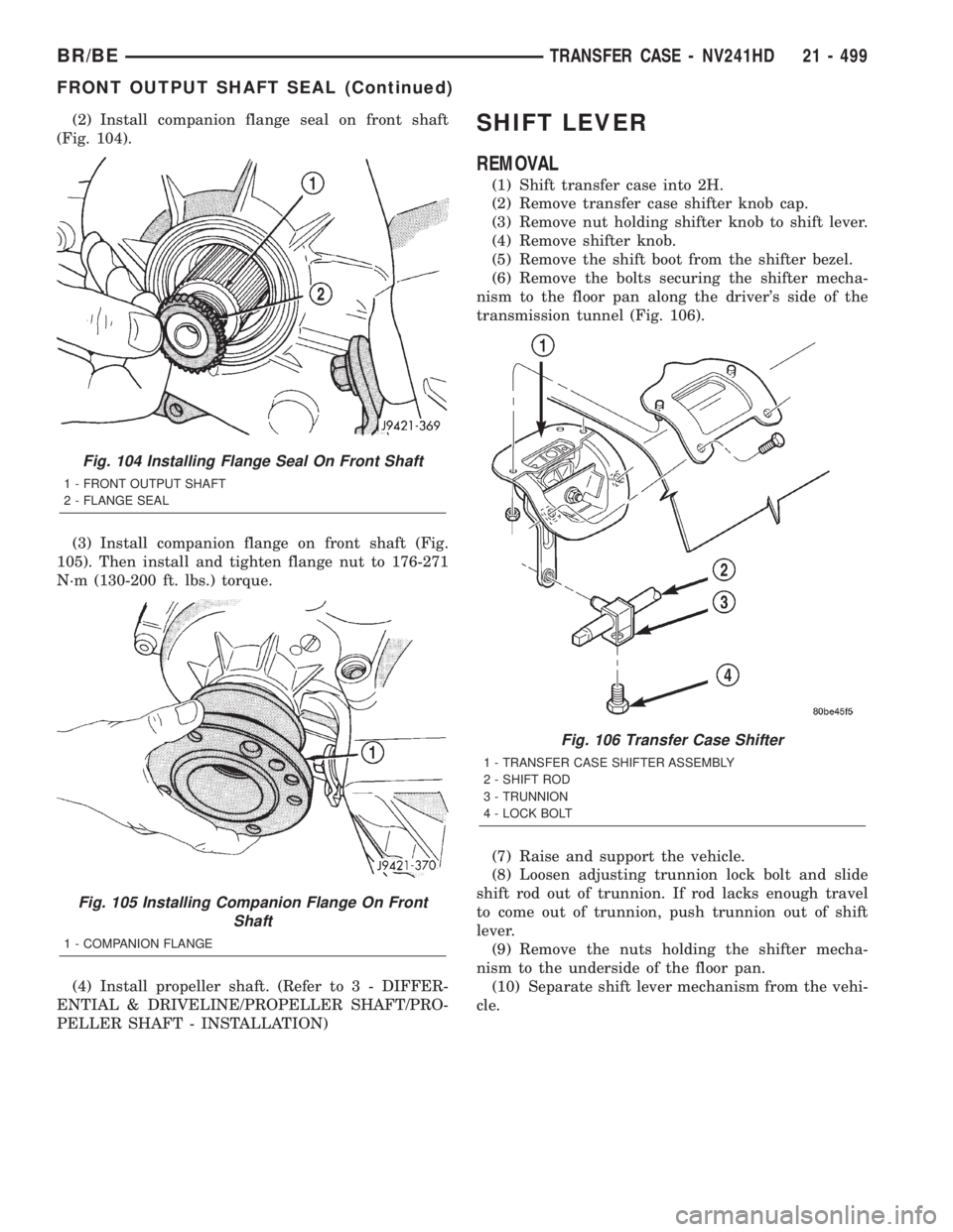
(2) Install companion flange seal on front shaft
(Fig. 104).
(3) Install companion flange on front shaft (Fig.
105). Then install and tighten flange nut to 176-271
N´m (130-200 ft. lbs.) torque.
(4) Install propeller shaft. (Refer to 3 - DIFFER-
ENTIAL & DRIVELINE/PROPELLER SHAFT/PRO-
PELLER SHAFT - INSTALLATION)SHIFT LEVER
REMOVAL
(1) Shift transfer case into 2H.
(2) Remove transfer case shifter knob cap.
(3) Remove nut holding shifter knob to shift lever.
(4) Remove shifter knob.
(5) Remove the shift boot from the shifter bezel.
(6) Remove the bolts securing the shifter mecha-
nism to the floor pan along the driver's side of the
transmission tunnel (Fig. 106).
(7) Raise and support the vehicle.
(8) Loosen adjusting trunnion lock bolt and slide
shift rod out of trunnion. If rod lacks enough travel
to come out of trunnion, push trunnion out of shift
lever.
(9) Remove the nuts holding the shifter mecha-
nism to the underside of the floor pan.
(10) Separate shift lever mechanism from the vehi-
cle.
Fig. 104 Installing Flange Seal On Front Shaft
1 - FRONT OUTPUT SHAFT
2 - FLANGE SEAL
Fig. 105 Installing Companion Flange On Front
Shaft
1 - COMPANION FLANGE
Fig. 106 Transfer Case Shifter
1 - TRANSFER CASE SHIFTER ASSEMBLY
2 - SHIFT ROD
3 - TRUNNION
4 - LOCK BOLT
BR/BETRANSFER CASE - NV241HD 21 - 499
FRONT OUTPUT SHAFT SEAL (Continued)
Page 1953 of 2255
INSTALLATION
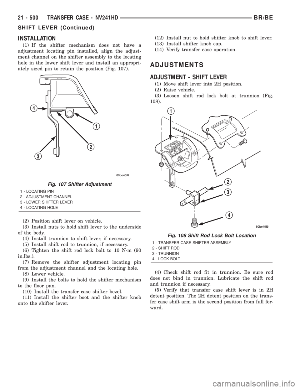
(1) If the shifter mechanism does not have a
adjustment locating pin installed, align the adjust-
ment channel on the shifter assembly to the locating
hole in the lower shift lever and install an appropri-
ately sized pin to retain the position (Fig. 107).
(2) Position shift lever on vehicle.
(3) Install nuts to hold shift lever to the underside
of the body.
(4) Install trunnion to shift lever, if necessary.
(5) Install shift rod to trunnion, if necessary.
(6) Tighten the shift rod lock bolt to 10 N´m (90
in.lbs.).
(7) Remove the shifter adjustment locating pin
from the adjustment channel and the locating hole.
(8) Lower vehicle.
(9) Install the bolts to hold the shifter mechanism
to the floor pan.
(10) Install the transfer case shifter bezel.
(11) Install the shifter boot and the shifter knob
onto the shifter lever.(12) Install nut to hold shifter knob to shift lever.
(13) Install shifter knob cap.
(14) Verify transfer case operation.
ADJUSTMENTS
ADJUSTMENT - SHIFT LEVER
(1) Move shift lever into 2H position.
(2) Raise vehicle.
(3) Loosen shift rod lock bolt at trunnion (Fig.
108).
(4) Check shift rod fit in trunnion. Be sure rod
does not bind in trunnion. Lubricate the shift rod
and trunnion if necessary.
(5) Verify that transfer case shift lever is in 2H
detent position. The 2H detent position on the trans-
fer case shift arm is the second position from full for-
ward.
Fig. 107 Shifter Adjustment
1 - LOCATING PIN
2 - ADJUSTMENT CHANNEL
3 - LOWER SHIFTER LEVER
4 - LOCATING HOLE
Fig. 108 Shift Rod Lock Bolt Location
1 - TRANSFER CASE SHIFTER ASSEMBLY
2 - SHIFT ROD
3 - TRUNNION
4 - LOCK BOLT
21 - 500 TRANSFER CASE - NV241HDBR/BE
SHIFT LEVER (Continued)
Page 1954 of 2255
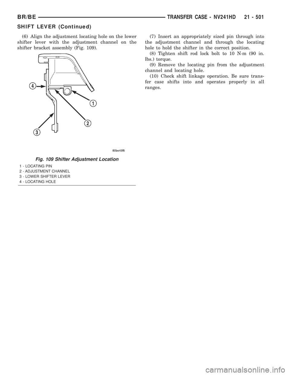
(6) Align the adjustment locating hole on the lower
shifter lever with the adjustment channel on the
shifter bracket assembly (Fig. 109).(7) Insert an appropriately sized pin through into
the adjustment channel and through the locating
hole to hold the shifter in the correct position.
(8) Tighten shift rod lock bolt to 10 N´m (90 in.
lbs.) torque.
(9) Remove the locating pin from the adjustment
channel and locating hole.
(10) Check shift linkage operation. Be sure trans-
fer case shifts into and operates properly in all
ranges.
Fig. 109 Shifter Adjustment Location
1 - LOCATING PIN
2 - ADJUSTMENT CHANNEL
3 - LOWER SHIFTER LEVER
4 - LOCATING HOLE
BR/BETRANSFER CASE - NV241HD 21 - 501
SHIFT LEVER (Continued)
Page 1961 of 2255
TIRES
DESCRIPTION
DESCRIPTION - SPARE TIRE - TEMPORARY
The temporary spare tire is designed for emer-
gency use only. The original tire should be repaired
or replaced at the first opportunity, then reinstalled.
Do not exceed speeds of 50 M.P.H. when using the
temporary spare tire. Refer to Owner's Manual for
complete details.
DESCRIPTION - TIRES
Tires are designed and engineered for each specific
vehicle. They provide the best overall performance
for normal operation. The ride and handling charac-
teristics match the vehicle's requirements. With
proper care they will give excellent reliability, trac-
tion, skid resistance, and tread life.
Driving habits have more effect on tire life than
any other factor. Careful drivers will obtain in most
cases, much greater mileage than severe use or care-
less drivers. A few of the driving habits which will
shorten the life of any tire are:
²Rapid acceleration
²Severe brake applications
²High speed driving
²Excessive speeds on turns
²Striking curbs and other obstacles
Radial-ply tires are more prone to irregular tread
wear. It is important to follow the tire rotation inter-
val shown in the section on Tire Rotation, (Refer to
22 - TIRES/WHEELS - STANDARD PROCEDURE).
This will help to achieve a greater tread life.
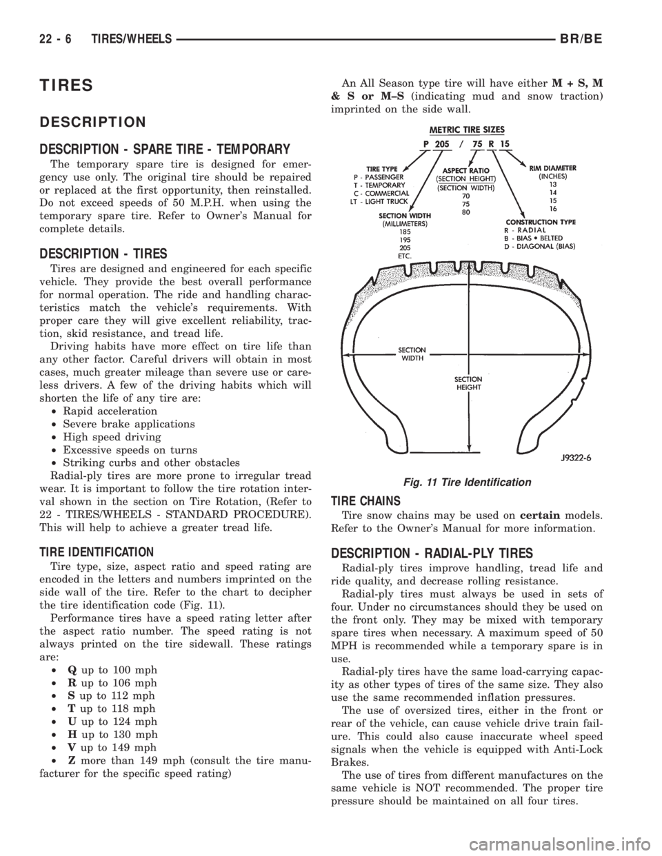
TIRE IDENTIFICATION
Tire type, size, aspect ratio and speed rating are
encoded in the letters and numbers imprinted on the
side wall of the tire. Refer to the chart to decipher
the tire identification code (Fig. 11).
Performance tires have a speed rating letter after
the aspect ratio number. The speed rating is not
always printed on the tire sidewall. These ratings
are:
²Qup to 100 mph
²Rup to 106 mph
²Sup to 112 mph
²Tup to 118 mph
²Uup to 124 mph
²Hup to 130 mph
²Vup to 149 mph
²Zmore than 149 mph (consult the tire manu-
facturer for the specific speed rating)An All Season type tire will have eitherM+S,M
&SorM±S(indicating mud and snow traction)
imprinted on the side wall.
TIRE CHAINS
Tire snow chains may be used oncertainmodels.
Refer to the Owner's Manual for more information.
DESCRIPTION - RADIAL-PLY TIRES
Radial-ply tires improve handling, tread life and
ride quality, and decrease rolling resistance.
Radial-ply tires must always be used in sets of
four. Under no circumstances should they be used on
the front only. They may be mixed with temporary
spare tires when necessary. A maximum speed of 50
MPH is recommended while a temporary spare is in
use.
Radial-ply tires have the same load-carrying capac-
ity as other types of tires of the same size. They also
use the same recommended inflation pressures.
The use of oversized tires, either in the front or
rear of the vehicle, can cause vehicle drive train fail-
ure. This could also cause inaccurate wheel speed
signals when the vehicle is equipped with Anti-Lock
Brakes.
The use of tires from different manufactures on the
same vehicle is NOT recommended. The proper tire
pressure should be maintained on all four tires.
Fig. 11 Tire Identification
22 - 6 TIRES/WHEELSBR/BE