Page 1916 of 2255

(7) Remove the shifter adjustment locating pin
from the adjustment channel and the locating hole.
(8) Lower vehicle.(9) Install the bolts to hold the shifter mechanism
to the floor pan.
(10) Install the transfer case shifter bezel.
(11) Install the shifter boot and the shifter knob
onto the shifter lever.
(12) Install nut to hold shifter knob to shift lever.
(13) Install shifter knob cap.
(14) Verify transfer case operation.
ADJUSTMENTS
ADJUSTMENT - SHIFT LEVER
(1) Move shift lever into 2H position.
(2) Raise vehicle.
(3) Loosen shift rod lock bolt at trunnion (Fig.
106).
(4) Check shift rod fit in trunnion. Be sure rod
does not bind in trunnion. Lubricate the shift rod
and trunnion if necessary.
Fig. 104 Transfer Case Shifter
1 - TRANSFER CASE SHIFTER ASSEMBLY
2 - SHIFT ROD
3 - TRUNNION
4 - LOCK BOLT
Fig. 105 Shifter Adjustment
1 - LOCATING PIN
2 - ADJUSTMENT CHANNEL
3 - LOWER SHIFTER LEVER
4 - LOCATING HOLE
Fig. 106 Shift Rod Lock Bolt Location
1 - TRANSFER CASE SHIFTER ASSEMBLY
2 - SHIFT ROD
3 - TRUNNION
4 - LOCK BOLT
BR/BETRANSFER CASE - NV241LD 21 - 463
SHIFT LEVER (Continued)
Page 1917 of 2255
(5) Verify that transfer case shift lever is in 2H
detent position. The 2H detent position on the trans-
fer case shift arm is the second position from full for-
ward.
(6) Align the adjustment locating hole on the lower
shifter lever with the adjustment channel on the
shifter bracket assembly (Fig. 107).
(7) Insert an appropriately sized pin through into
the adjustment channel and through the locating
hole to hold the shifter in the correct position.
(8) Tighten shift rod lock bolt to 10 N´m (90 in.
lbs.) torque.
(9) Remove the locating pin from the adjustment
channel and locating hole.
(10) Check shift linkage operation. Be sure trans-
fer case shifts into and operates properly in all
ranges.
Fig. 107 Shifter Adjustment Location
1 - LOCATING PIN
2 - ADJUSTMENT CHANNEL
3 - LOWER SHIFTER LEVER
4 - LOCATING HOLE
21 - 464 TRANSFER CASE - NV241LDBR/BE
SHIFT LEVER (Continued)
Page 1922 of 2255

REMOVAL
(1) Raise and support vehicle.
(2) Remove skid plate, if equipped. (Refer to 13 -
FRAMES & BUMPERS/FRAME/TRANSFER CASE
SKID PLATE - REMOVAL)
(3) Position drain oil container under transfer
case.
(4) Remove transfer case drain plug and drain
lubricant into container.
(5) Disconnect vent hose and vacuum harness at
transfer case switch.
(6) Disconnect shift rod from grommet in transfer
case shift lever, or from floor shift arm whichever
provides easy access. Use channel lock style pliers to
press rod out of lever grommet.
(7) Support transmission with jack stand.
(8) Remove rear crossmember.
(9) Mark front and rear propeller shafts for assem-
bly reference.
(10) Remove front and rear propeller shafts. (Refer
to 3 - DIFFERENTIAL & DRIVELINE/PROPELLER
SHAFT/PROPELLER SHAFT - REMOVAL)
(11) Support transfer case with suitable jack.
Secure transfer case to jack with safety chains.
(12) Remove nuts attaching transfer case to trans-
mission.
(13) Move transfer case assembly rearward until
free of transmission output shaft.
(14) Lower jack and move transfer case from
under vehicle.
DISASSEMBLY
Position transfer case in a shallow drain pan.
Remove drain plug and drain any remaining lubri-
cant remaining in case.
EXTENSION HOUSING
(1) Remove extension housing snap-ring access
cover.
(2) Remove bolts holding extension housing to rear
case half.
(3) Tap extension housing with plastic or rawhide
hammer to loosen sealant.
(4) Disengage extension housing snap-ring from
rear output shaft bearing.
(5) Separate extension housing from transfer case.
COMPANION FLANGE AND SHIFT LEVER
(1) Shift transfer case into NEUTRAL.
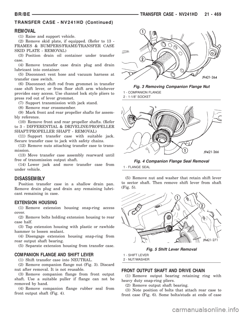
(2) Remove companion flange nut (Fig. 3). Discard
nut after removal. It is not reusable.
(3) Remove companion flange from front output
shaft. Use a suitable puller if flange can not be
removed by hand.
(4) Remove companion flange rubber seal from
front output shaft (Fig. 4).(5) Remove nut and washer that retain shift lever
to sector shaft. Then remove shift lever from shaft
(Fig. 5).
FRONT OUTPUT SHAFT AND DRIVE CHAIN
(1) Remove output bearing retaining ring with
heavy duty snap-ring pliers.
(2) Remove output shaft bearing.
(3) Note position of bolts that attach rear case to
front case (Fig. 6). Some bolts/studs at ends of case
Fig. 3 Removing Companion Flange Nut
1 - COMPANION FLANGE
2 - 1-1/8º SOCKET
Fig. 4 Companion Flange Seal Removal
1 - FLANGE SEAL
Fig. 5 Shift Lever Removal
1 - SHIFT LEVER
2 - NUT/WASHER
BR/BETRANSFER CASE - NV241HD 21 - 469
TRANSFER CASE - NV241HD (Continued)
Page 1929 of 2255

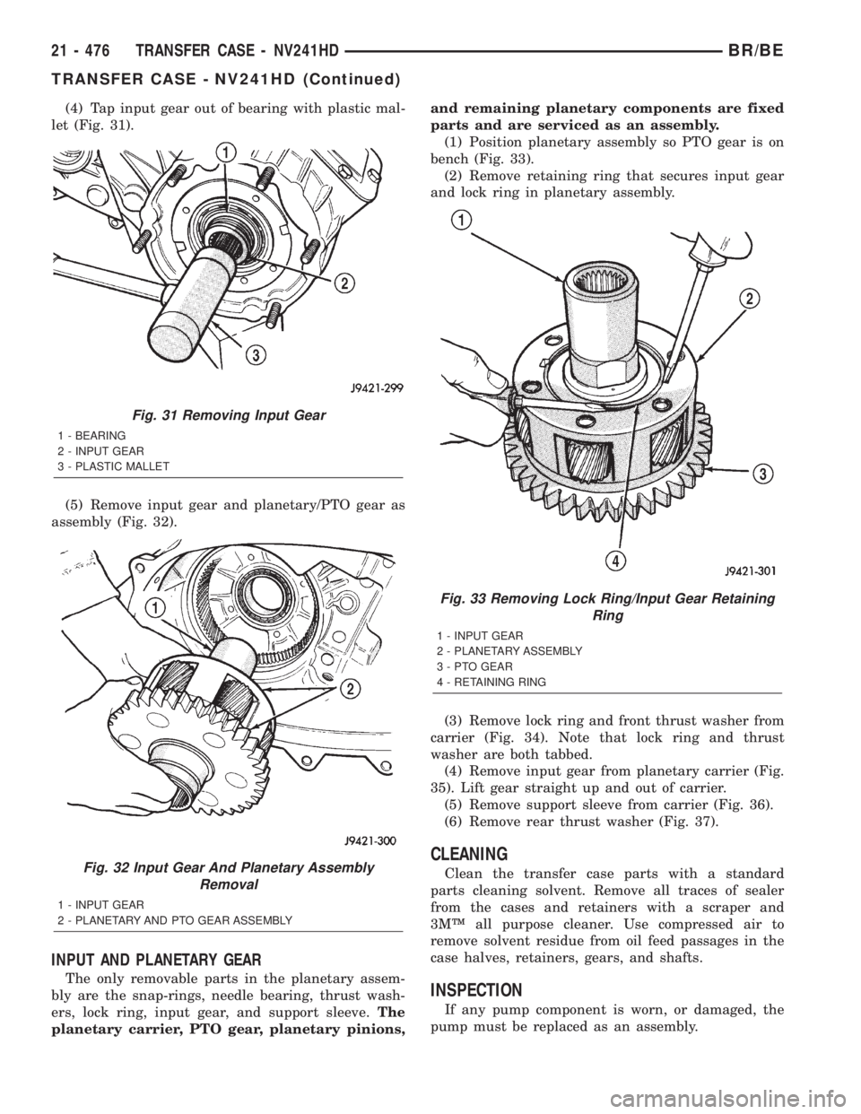
(4) Tap input gear out of bearing with plastic mal-
let (Fig. 31).
(5) Remove input gear and planetary/PTO gear as
assembly (Fig. 32).
INPUT AND PLANETARY GEAR
The only removable parts in the planetary assem-
bly are the snap-rings, needle bearing, thrust wash-
ers, lock ring, input gear, and support sleeve.The
planetary carrier, PTO gear, planetary pinions,and remaining planetary components are fixed
parts and are serviced as an assembly.
(1) Position planetary assembly so PTO gear is on
bench (Fig. 33).
(2) Remove retaining ring that secures input gear
and lock ring in planetary assembly.
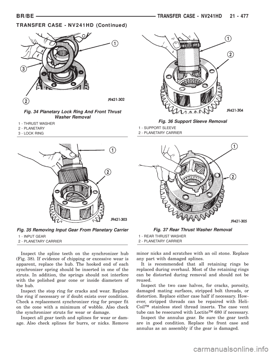
(3) Remove lock ring and front thrust washer from
carrier (Fig. 34). Note that lock ring and thrust
washer are both tabbed.
(4) Remove input gear from planetary carrier (Fig.
35). Lift gear straight up and out of carrier.
(5) Remove support sleeve from carrier (Fig. 36).
(6) Remove rear thrust washer (Fig. 37).
CLEANING
Clean the transfer case parts with a standard
parts cleaning solvent. Remove all traces of sealer
from the cases and retainers with a scraper and
3MŸ all purpose cleaner. Use compressed air to
remove solvent residue from oil feed passages in the
case halves, retainers, gears, and shafts.
INSPECTION
If any pump component is worn, or damaged, the
pump must be replaced as an assembly.
Fig. 31 Removing Input Gear
1 - BEARING
2 - INPUT GEAR
3 - PLASTIC MALLET
Fig. 32 Input Gear And Planetary Assembly
Removal
1 - INPUT GEAR
2 - PLANETARY AND PTO GEAR ASSEMBLY
Fig. 33 Removing Lock Ring/Input Gear Retaining
Ring
1 - INPUT GEAR
2 - PLANETARY ASSEMBLY
3 - PTO GEAR
4 - RETAINING RING
21 - 476 TRANSFER CASE - NV241HDBR/BE
TRANSFER CASE - NV241HD (Continued)
Page 1930 of 2255

Inspect the spline teeth on the synchronizer hub
(Fig. 38). If evidence of chipping or excessive wear is
apparent, replace the hub. The hooked end of each
synchronizer spring should be inserted in one of the
struts. In addition, the springs should not interfere
with the polished gear cone or inside diameters of
the hub.
Inspect the stop ring for cracks and wear. Replace
the ring if necessary or if doubt exists over condition.
Check a replacement synchronizer ring for proper fit
on the cone with a minimum of wobble. Also check
the synchronizer struts for wear or damage.
Inspect all gear teeth and splines for wear or dam-
age. Also check splines for burrs, or nicks. Removeminor nicks and scratches with an oil stone. Replace
any part with damaged splines.
It is recommended that all retaining rings be
replaced during overhaul. Most of the retaining rings
can be distorted during removal and should not be
reused.
Inspect the two case halves, for cracks, porosity,
damaged mating surfaces, stripped bolt threads, or
distortion. Replace either case half if necessary. How-
ever, stripped threads can be repaired with Heli-
CoilŸ stainless steel thread inserts. The case vent
tube can be resecured with LoctiteŸ 680 if necessary.
Inspect the annulus gear. Be sure the gear teeth
are in good condition. Replace the front case and
annulus as an assembly if the gear is damaged.
Fig. 34 Planetary Lock Ring And Front Thrust
Washer Removal
1 - THRUST WASHER
2 - PLANETARY
3 - LOCK RING
Fig. 35 Removing Input Gear From Planetary Carrier
1 - INPUT GEAR
2 - PLANETARY CARRIER
Fig. 36 Support Sleeve Removal
1 - SUPPORT SLEEVE
2 - PLANETARY CARRIER
Fig. 37 Rear Thrust Washer Removal
1 - REAR THRUST WASHER
2 - PLANETARY CARRIER
BR/BETRANSFER CASE - NV241HD 21 - 477
TRANSFER CASE - NV241HD (Continued)
Page 1932 of 2255
Fig. 40 Shift Fork Components
1 - SUPPORT SLEEVE 5 - MODE FORK AND SHIFT RAIL
2 - RANGE FORK 6 - SPRING
3 - SHIFT SECTOR 7 - CUP
4 - POPPET PLUNGER, SPRING, SCREW 8 - SLIDING CLUTCH
Fig. 41 Planetary And Input Gear Components
1 - LOCK RING 6 - RETAINING RING
2 - THRUST WASHERS 7 - SUPPORT SLEEVE
3 - PLANETARY CARRIER 8 - INPUT GEAR
4 - PTO GEAR 9 - RETAINING RING
5 - BEARING
BR/BETRANSFER CASE - NV241HD 21 - 479
TRANSFER CASE - NV241HD (Continued)
Page 1936 of 2255
INPUT AND PLANETARY GEAR
(1) Lubricate planetary components with transmis-
sion fluid.
(2) Install first thrust washer in carrier (Fig. 55).
Lube washer with petroleum jelly before installation.
(3) Support carrier with wood blocks under PTO
gear (Fig. 56).
(4) Install support sleeve in planetary carrier. Be
sure sleeve is seated.
Fig. 53 Output Shaft Rear Bearing Installation
1 - HANDLE C-4171
2 - OUTPUT SHAFT INNER BEARING
3 - INSTALLER 5066
Fig. 54 Output Shaft Rear Bearing Installation Depth
1 - BEARING (SEATED) AT LOWER EDGE OF CHAMFER
2 - CHAMFER
Fig. 55 Thrust Washer Installation
1 - THRUST WASHER
2 - TABS IN SLOTS
Fig. 56 Support Sleeve Installation
1 - PLANETARY
2 - SUPPORT SLEEVE
3 - WOOD BLOCKS
BR/BETRANSFER CASE - NV241HD 21 - 483
TRANSFER CASE - NV241HD (Continued)
Page 1937 of 2255
(5) Install input gear in planetary carrier (Fig. 57).
(6) Install second thrust washer in planetary car-
rier. Be sure washer tabs are seated in carrier slots.
(7) Install lock ring (Fig. 58).(8) Install retaining ring (Fig. 59).
INPUT AND PLANETARY GEAR
(1) Lubricate planetary pinions and annulus gear
with transmission fluid.
(2) Install planetary/input gear assembly in case
(Fig. 60).
(3) Start planetary pinions in low range annulus
gear. Then tap PTO gear, with hammer handle to
seat planetary pinions in annulus gear.
Fig. 57 Input Gear And Thrust Washer Installation
1 - INPUT GEAR
2 - THRUST WASHER
3 - TABS IN SLOTS
Fig. 58 Lock Ring Installation
1 - LOCK RING (BE SURE TABS ARE SEATED IN SLOTS)
Fig. 59 Retaining Ring Installation
1 - RETAINING RING
Fig. 60 Planetary/Input Gear Assembly Installation
1 - WOOD/RUBBER HAMMER HANDLE
2 - PLANETARY ASSEMBLY
21 - 484 TRANSFER CASE - NV241HDBR/BE
TRANSFER CASE - NV241HD (Continued)