2002 DODGE RAM lock
[x] Cancel search: lockPage 1969 of 2255
DIAGNOSIS AND TESTING
DIAGNOSIS AND TESTING - WATER LEAKS
Water leaks can be caused by poor sealing,
improper body component alignment, body seam
porosity, missing plugs, or blocked drain holes. Cen-
trifugal and gravitational force can cause water to
drip from a location away from the actual leak point,
making leak detection difficult. All body sealing
points should be water tight in normal wet-driving
conditions. Water flowing downward from the front of
the vehicle should not enter the passenger or luggage
compartment. Moving sealing surfaces will not
always seal water tight under all conditions. At
times, side glass or door seals will allow water to
enter the passenger compartment during high pres-
sure washing or hard driving rain (severe) condi-
tions. Overcompensating on door or glass
adjustments to stop a water leak that occurs under
severe conditions can cause premature seal wear and
excessive closing or latching effort. After completing
a repair, water test vehicle to verify leak has stopped
before returning vehicle to use.
VISUAL INSPECTION BEFORE WATER LEAK TESTS
Verify that floor and body plugs are in place, body
drains are clear, and body components are properly
aligned and sealed. If component alignment or seal-
ing is necessary, refer to the appropriate section of
this group for proper procedures.
WATER LEAK TESTS
WARNING: DO NOT USE ELECTRIC SHOP LIGHTS
OR TOOLS IN WATER TEST AREA. PERSONAL
INJURY CAN RESULT.
When the conditions causing a water leak have
been determined, simulate the conditions as closely
as possible.
²If a leak occurs with the vehicle parked in a
steady light rain, flood the leak area with an open-
ended garden hose.²If a leak occurs while driving at highway speeds
in a steady rain, test the leak area with a reasonable
velocity stream or fan spray of water. Direct the
spray in a direction comparable to actual conditions.
²If a leak occurs when the vehicle is parked on an
incline, hoist the end or side of the vehicle to simu-
late this condition. This method can be used when
the leak occurs when the vehicle accelerates, stops or
turns. If the leak occurs on acceleration, hoist the
front of the vehicle. If the leak occurs when braking,
hoist the back of the vehicle. If the leak occurs on left
turns, hoist the left side of the vehicle. If the leak
occurs on right turns, hoist the right side of the vehi-
cle. For hoisting recommendations refer to Group 0,
Lubrication and Maintenance, General Information
section.
WATER LEAK DETECTION
To detect a water leak point-of-entry, do a water
test and watch for water tracks or droplets forming
on the inside of the vehicle. If necessary, remove inte-
rior trim covers or panels to gain visual access to the
leak area. If the hose cannot be positioned without
being held, have someone help do the water test.
Some water leaks must be tested for a considerable
length of time to become apparent. When a leak
appears, find the highest point of the water track or
drop. The highest point usually will show the point of
entry. After leak point has been found, repair the
leak and water test to verify that the leak has
stopped.
Locating the entry point of water that is leaking
into a cavity between panels can be difficult. The
trapped water may splash or run from the cavity,
often at a distance from the entry point. Most water
leaks of this type become apparent after accelerating,
stopping, turning, or when on an incline.
MIRROR INSPECTION METHOD
When a leak point area is visually obstructed, use
a suitable mirror to gain visual access. A mirror can
also be used to deflect light to a limited-access area
to assist in locating a leak point.
23 - 2 BODYBR/BE
BODY (Continued)
Page 2034 of 2255
SLAM BUMPER
REMOVAL
(1) Open tailgate.
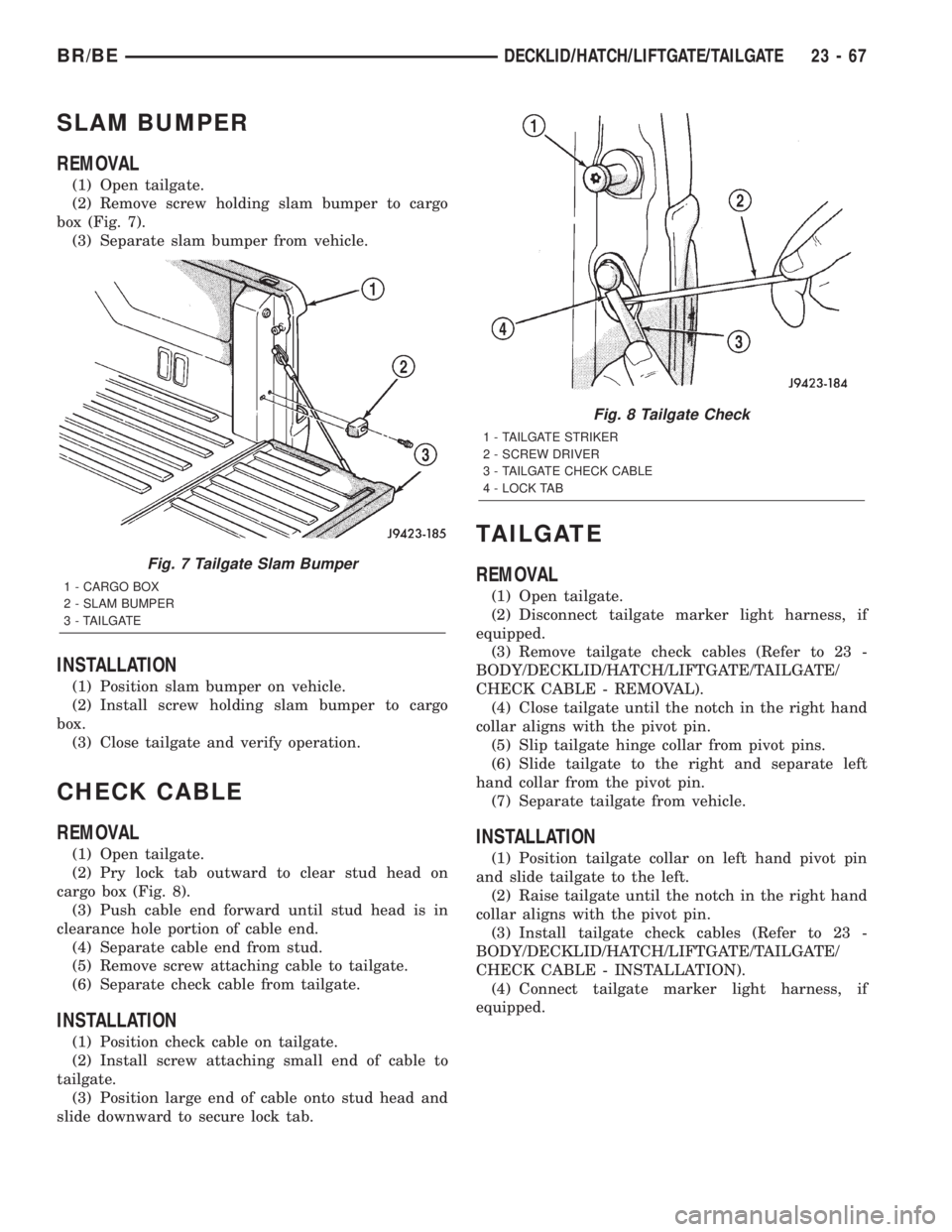
(2) Remove screw holding slam bumper to cargo
box (Fig. 7).
(3) Separate slam bumper from vehicle.
INSTALLATION
(1) Position slam bumper on vehicle.
(2) Install screw holding slam bumper to cargo
box.
(3) Close tailgate and verify operation.
CHECK CABLE
REMOVAL
(1) Open tailgate.
(2) Pry lock tab outward to clear stud head on
cargo box (Fig. 8).
(3) Push cable end forward until stud head is in
clearance hole portion of cable end.
(4) Separate cable end from stud.
(5) Remove screw attaching cable to tailgate.
(6) Separate check cable from tailgate.
INSTALLATION
(1) Position check cable on tailgate.
(2) Install screw attaching small end of cable to
tailgate.
(3) Position large end of cable onto stud head and
slide downward to secure lock tab.
TAILGATE
REMOVAL
(1) Open tailgate.
(2) Disconnect tailgate marker light harness, if
equipped.
(3) Remove tailgate check cables (Refer to 23 -
BODY/DECKLID/HATCH/LIFTGATE/TAILGATE/
CHECK CABLE - REMOVAL).
(4) Close tailgate until the notch in the right hand
collar aligns with the pivot pin.
(5) Slip tailgate hinge collar from pivot pins.
(6) Slide tailgate to the right and separate left
hand collar from the pivot pin.
(7) Separate tailgate from vehicle.
INSTALLATION
(1) Position tailgate collar on left hand pivot pin
and slide tailgate to the left.
(2) Raise tailgate until the notch in the right hand
collar aligns with the pivot pin.
(3) Install tailgate check cables (Refer to 23 -
BODY/DECKLID/HATCH/LIFTGATE/TAILGATE/
CHECK CABLE - INSTALLATION).
(4) Connect tailgate marker light harness, if
equipped.
Fig. 7 Tailgate Slam Bumper
1 - CARGO BOX
2 - SLAM BUMPER
3 - TAILGATE
Fig. 8 Tailgate Check
1 - TAILGATE STRIKER
2 - SCREW DRIVER
3 - TAILGATE CHECK CABLE
4 - LOCK TAB
BR/BEDECKLID/HATCH/LIFTGATE/TAILGATE 23 - 67
Page 2035 of 2255
DOOR - FRONT
TABLE OF CONTENTS
page page
APPLIQUE
REMOVAL.............................68
INSTALLATION.........................68
DOOR
REMOVAL.............................69
INSTALLATION.........................69
ADJUSTMENTS
ADJUSTMENT - FRONT DOOR FORE/AFT . . 69
ADJUSTMENT - FRONT DOOR UP/DOWN . . 70
ADJUSTMENT - FRONT DOOR IN/OUT.....70
DOOR GLASS
REMOVAL.............................70
INSTALLATION.........................70
EXTERIOR HANDLE
REMOVAL.............................71
INSTALLATION.........................71
GLASS RUN CHANNEL
REMOVAL.............................71
INSTALLATION.........................71
HINGE
REMOVAL.............................72
INSTALLATION.........................72
INSIDE HANDLE ACTUATOR
REMOVAL.............................72INSTALLATION.........................72
LATCH
REMOVAL.............................72
INSTALLATION.........................73
ADJUSTMENTS
ADJUSTMENT - FRONT DOOR LATCH.....73
LATCH STRIKER
REMOVAL.............................73
INSTALLATION.........................73
LOCK CYLINDER
REMOVAL.............................74
INSTALLATION.........................74
SIDE VIEW MIRROR FLAG
REMOVAL.............................74
INSTALLATION.........................75
TRIM PANEL
REMOVAL.............................75
INSTALLATION.........................75
WATERDAM
REMOVAL.............................76
INSTALLATION.........................76
WINDOW REGULATOR
REMOVAL.............................76
INSTALLATION.........................76
APPLIQUE
REMOVAL
(1) Using a heat lamp, warm B-pillar to 38É C
(100É F).
(2) Remove glass run weatherstrip (Refer to 23 -
BODY/WEATHERSTRIP/SEALS/FDR GLASS RUN
WEATHERSTRIP - REMOVAL).
(3) Remove outer belt weatherstrip (Refer to 23 -
BODY/WEATHERSTRIP/SEALS/FDR OUTER BELT
WEATHERSTRIP - REMOVAL).
(4) Using an even pressure pull, peel B-pillar
applique away from the B-pillar.
INSTALLATION
Installation equipment needed:
²Lint free applicator cloth
²six inch applicator squeegee
²Piercing pin
(1) Clean B-pillar using Mopar Super Kleen or
equivalent.
(2) Wipe surface with a lint free cloth.(3) Using a heat gun, warm surface to 22É C (70É
F).
(4) Fold down, up/down locator tab (1a or 1b) (Fig.
1) along crease.
(5) Remove carrier from adhesion strip (2).
(6) Using up/down locator tab (1a or 1b) and fore/
aft locator tab (3a or 3b), position the applique on the
upper portion of the B-pillar.
(7) Using the lower edge locator (4), position the
applique on the lower portion of the B-pillar.
(8) Verify the applique is positioned correctly and
press the adhesion strip (2) to the door to tempo-
rarily secure it in place.
(9) Remove the carrier for the applique.
(10) Holding the applique from the surface, apply
firm downward pressure with a six inch applicator
squeegee. Ensure the lower rear edge (4) is aligned
correctly.
(11) Wrap edges around door to at least a 90É
angle.
(12) Remove premask by pulling in a firm contin-
uous manner from top down at 180É.
(13) Complete wrapping applique around the door
edges.
23 - 68 DOOR - FRONTBR/BE
Page 2038 of 2255
(5) Install inner door belt weatherstrip (Refer to
23 - BODY/WEATHERSTRIP/SEALS/FDR INNER
BELT WEATHERSTRIP - INSTALLATION).
(6) Install the door waterdam (Refer to 23 - BODY/
DOOR - FRONT/WATERDAM - INSTALLATION).
EXTERIOR HANDLE
REMOVAL
(1) Remove the waterdam (Refer to 23 - BODY/
DOOR - FRONT/WATERDAM - REMOVAL).
(2) Raise the window to the closed position.
(3) Remove fastener access plug from door end
panel.
(4) Disengage clips holding latch and lock rods to
door latch.
(5) Separate latch and lock rods from door latch.
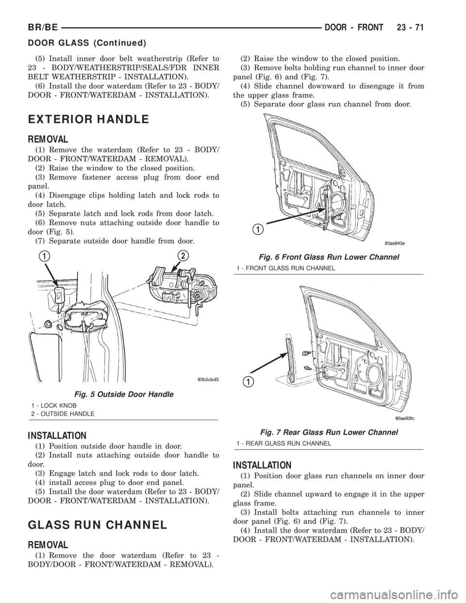
(6) Remove nuts attaching outside door handle to
door (Fig. 5).
(7) Separate outside door handle from door.
INSTALLATION
(1) Position outside door handle in door.
(2) Install nuts attaching outside door handle to
door.
(3) Engage latch and lock rods to door latch.
(4) install access plug to door end panel.
(5) Install the door waterdam (Refer to 23 - BODY/
DOOR - FRONT/WATERDAM - INSTALLATION).
GLASS RUN CHANNEL
REMOVAL
(1) Remove the door waterdam (Refer to 23 -
BODY/DOOR - FRONT/WATERDAM - REMOVAL).(2) Raise the window to the closed position.
(3) Remove bolts holding run channel to inner door
panel (Fig. 6) and (Fig. 7).
(4) Slide channel downward to disengage it from
the upper glass frame.
(5) Separate door glass run channel from door.
INSTALLATION
(1) Position door glass run channels on inner door
panel.
(2) Slide channel upward to engage it in the upper
glass frame.
(3) Install bolts attaching run channels to inner
door panel (Fig. 6) and (Fig. 7).
(4) Install the door waterdam (Refer to 23 - BODY/
DOOR - FRONT/WATERDAM - INSTALLATION).
Fig. 5 Outside Door Handle
1 - LOCK KNOB
2 - OUTSIDE HANDLE
Fig. 6 Front Glass Run Lower Channel
1 - FRONT GLASS RUN CHANNEL
Fig. 7 Rear Glass Run Lower Channel
1 - REAR GLASS RUN CHANNEL
BR/BEDOOR - FRONT 23 - 71
DOOR GLASS (Continued)
Page 2039 of 2255
HINGE
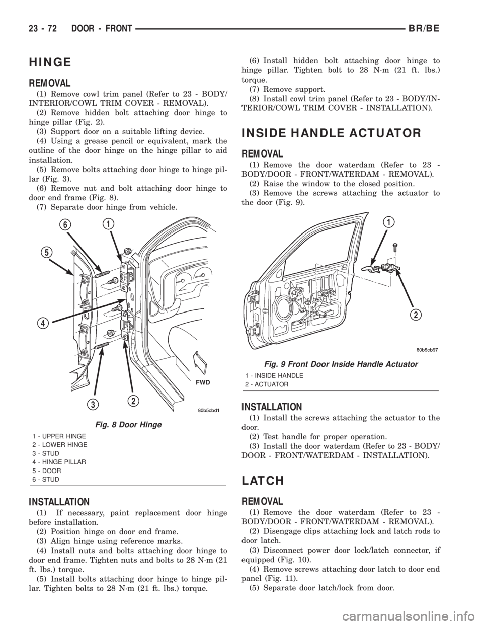
REMOVAL
(1) Remove cowl trim panel (Refer to 23 - BODY/
INTERIOR/COWL TRIM COVER - REMOVAL).
(2) Remove hidden bolt attaching door hinge to
hinge pillar (Fig. 2).
(3) Support door on a suitable lifting device.
(4) Using a grease pencil or equivalent, mark the
outline of the door hinge on the hinge pillar to aid
installation.
(5) Remove bolts attaching door hinge to hinge pil-
lar (Fig. 3).
(6) Remove nut and bolt attaching door hinge to
door end frame (Fig. 8).
(7) Separate door hinge from vehicle.
INSTALLATION
(1) If necessary, paint replacement door hinge
before installation.
(2) Position hinge on door end frame.
(3) Align hinge using reference marks.
(4) Install nuts and bolts attaching door hinge to
door end frame. Tighten nuts and bolts to 28 N´m (21
ft. lbs.) torque.
(5) Install bolts attaching door hinge to hinge pil-
lar. Tighten bolts to 28 N´m (21 ft. lbs.) torque.(6) Install hidden bolt attaching door hinge to
hinge pillar. Tighten bolt to 28 N´m (21 ft. lbs.)
torque.
(7) Remove support.
(8) Install cowl trim panel (Refer to 23 - BODY/IN-
TERIOR/COWL TRIM COVER - INSTALLATION).
INSIDE HANDLE ACTUATOR
REMOVAL
(1) Remove the door waterdam (Refer to 23 -
BODY/DOOR - FRONT/WATERDAM - REMOVAL).
(2) Raise the window to the closed position.
(3) Remove the screws attaching the actuator to
the door (Fig. 9).
INSTALLATION
(1) Install the screws attaching the actuator to the
door.
(2) Test handle for proper operation.
(3) Install the door waterdam (Refer to 23 - BODY/
DOOR - FRONT/WATERDAM - INSTALLATION).
LATCH
REMOVAL
(1) Remove the door waterdam (Refer to 23 -
BODY/DOOR - FRONT/WATERDAM - REMOVAL).
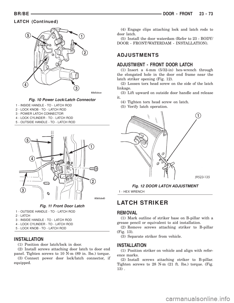
(2) Disengage clips attaching lock and latch rods to
door latch.
(3) Disconnect power door lock/latch connector, if
equipped (Fig. 10).
(4) Remove screws attaching door latch to door end
panel (Fig. 11).
(5) Separate door latch/lock from door.
Fig. 8 Door Hinge
1 - UPPER HINGE
2 - LOWER HINGE
3 - STUD
4 - HINGE PILLAR
5 - DOOR
6 - STUD
Fig. 9 Front Door Inside Handle Actuator
1 - INSIDE HANDLE
2 - ACTUATOR
23 - 72 DOOR - FRONTBR/BE
Page 2040 of 2255
INSTALLATION
(1) Position door latch/lock in door.
(2) Install screws attaching door latch to door end
panel. Tighten screws to 10 N´m (89 in. lbs.) torque.
(3) Connect power door lock/latch connector, if
equipped.(4) Engage clips attaching lock and latch rods to
door latch.
(5) Install the door waterdam (Refer to 23 - BODY/
DOOR - FRONT/WATERDAM - INSTALLATION).
ADJUSTMENTS
ADJUSTMENT - FRONT DOOR LATCH
(1) Insert a 4-mm (5/32-in) hex-wrench through
the elongated hole in the door end frame near the
latch striker opening (Fig. 12).
(2) Loosen torx head screw on the side of the latch
linkage.
(3) Lift upward on outside door handle and release
it.
(4) Tighten torx head screw on latch.
(5) Verify latch operation.
LATCH STRIKER
REMOVAL
(1) Mark outline of striker base on B-pillar with a
grease pencil or equivalent to aid installation.
(2) Remove screws attaching striker to B-pillar
(Fig. 13).
(3) Separate striker from vehicle.
INSTALLATION
(1) Position striker on vehicle and align with refer-
ence marks.
(2) Install screws attaching striker to B-pillar.
Tighten screws to 28 N´m (21 ft. lbs.) torque. (Fig.
13) .
Fig. 10 Power Lock/Latch Connector
1 - INSIDE HANDLE - TO - LATCH ROD
2 - LOCK KNOB - TO - LATCH ROD
3 - POWER LATCH CONNECTOR
4 - LOCK CYLINDER - TO - LATCH ROD
5 - OUTSIDE HANDLE - TO - LATCH ROD
Fig. 11 Front Door Latch
1 - OUTSIDE HANDLE - TO - LATCH ROD
2-LATCH
3 - INSIDE HANDLE - TO - LATCH ROD
4 - LOCK CYLINDER - TO - LATCH ROD
5 - LOCK KNOB - TO - LATCH ROD
Fig. 12 DOOR LATCH ADJUSTMENT
1 - HEX WRENCH
BR/BEDOOR - FRONT 23 - 73
LATCH (Continued)
Page 2041 of 2255
LOCK CYLINDER
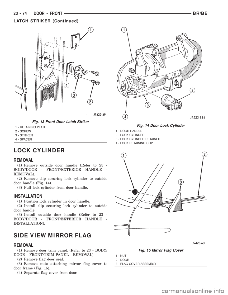
REMOVAL
(1) Remove outside door handle (Refer to 23 -
BODY/DOOR - FRONT/EXTERIOR HANDLE -
REMOVAL).
(2) Remove clip securing lock cylinder to outside
door handle (Fig. 14).
(3) Pull lock cylinder from door handle.
INSTALLATION
(1) Position lock cylinder in door handle.
(2) Install clip securing lock cylinder to outside
door handle.
(3) Install outside door handle (Refer to 23 -
BODY/DOOR - FRONT/EXTERIOR HANDLE -
INSTALLATION).
SIDE VIEW MIRROR FLAG
REMOVAL
(1) Remove door trim panel. (Refer to 23 - BODY/
DOOR - FRONT/TRIM PANEL - REMOVAL)
(2) Remove flag door seal.
(3) Remove nuts attaching mirror flag cover to
door frame (Fig. 15).
(4) Separate flag cover from door.
Fig. 13 Front Door Latch Striker
1 - RETAINING PLATE
2 - SCREW
3 - STRIKER
4 - SPACERFig. 14 Door Lock Cylinder
1 - DOOR HANDLE
2 - LOCK CYLINDER
3 - LOCK CYLINDER RETAINER
4 - LOCK RETAINING CLIP
Fig. 15 Mirror Flag Cover
1 - NUT
2 - DOOR
3 - FLAG COVER ASSEMBLY
23 - 74 DOOR - FRONTBR/BE
LATCH STRIKER (Continued)
Page 2042 of 2255
INSTALLATION
(1) Position flag cover on door.
(2) Install nuts attaching mirror flag cover to door
frame.
(3) Install flag door seal.
(4) Install door trim panel. (Refer to 23 - BODY/
DOOR - FRONT/TRIM PANEL - INSTALLATION)
TRIM PANEL
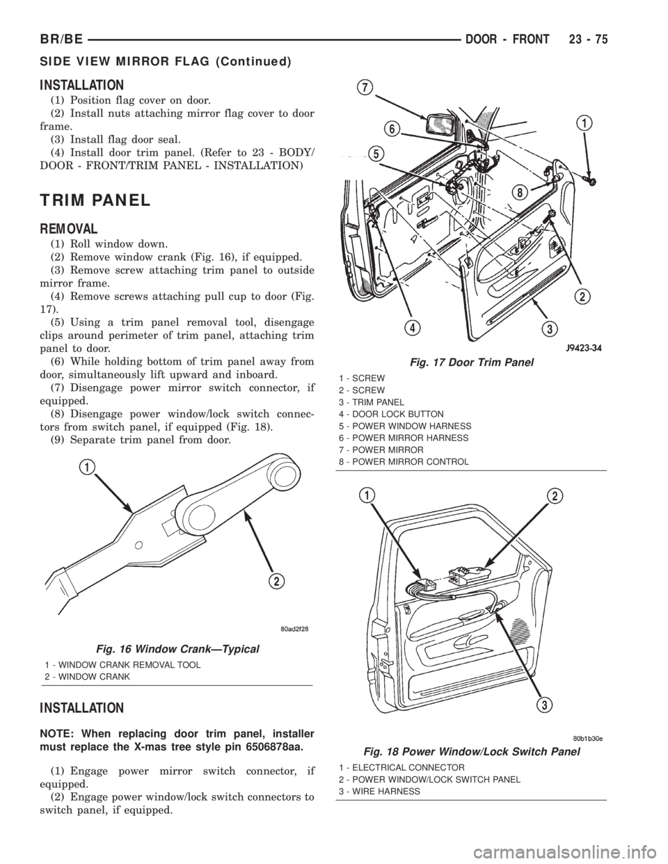
REMOVAL
(1) Roll window down.
(2) Remove window crank (Fig. 16), if equipped.
(3) Remove screw attaching trim panel to outside
mirror frame.
(4) Remove screws attaching pull cup to door (Fig.
17).
(5) Using a trim panel removal tool, disengage
clips around perimeter of trim panel, attaching trim
panel to door.
(6) While holding bottom of trim panel away from
door, simultaneously lift upward and inboard.
(7) Disengage power mirror switch connector, if
equipped.
(8) Disengage power window/lock switch connec-
tors from switch panel, if equipped (Fig. 18).
(9) Separate trim panel from door.
INSTALLATION
NOTE: When replacing door trim panel, installer
must replace the X-mas tree style pin 6506878aa.
(1) Engage power mirror switch connector, if
equipped.
(2) Engage power window/lock switch connectors to
switch panel, if equipped.
Fig. 16 Window CrankÐTypical
1 - WINDOW CRANK REMOVAL TOOL
2 - WINDOW CRANK
Fig. 17 Door Trim Panel
1 - SCREW
2 - SCREW
3 - TRIM PANEL
4 - DOOR LOCK BUTTON
5 - POWER WINDOW HARNESS
6 - POWER MIRROR HARNESS
7 - POWER MIRROR
8 - POWER MIRROR CONTROL
Fig. 18 Power Window/Lock Switch Panel
1 - ELECTRICAL CONNECTOR
2 - POWER WINDOW/LOCK SWITCH PANEL
3 - WIRE HARNESS
BR/BEDOOR - FRONT 23 - 75
SIDE VIEW MIRROR FLAG (Continued)