2002 DODGE RAM lock
[x] Cancel search: lockPage 2145 of 2255
WARNING: ON VEHICLES EQUIPPED WITH AIR-
BAGS, DISABLE THE AIRBAG SYSTEM BEFORE
ATTEMPTING ANY STEERING WHEEL, STEERING
COLUMN, OR INSTRUMENT PANEL COMPONENT
DIAGNOSIS OR SERVICE. DISCONNECT AND ISO-
LATE THE BATTERY NEGATIVE (GROUND) CABLE,
THEN WAIT TWO MINUTES FOR THE AIRBAG SYS-
TEM CAPACITOR TO DISCHARGE BEFORE PER-
FORMING FURTHER DIAGNOSIS OR SERVICE. THIS
IS THE ONLY SURE WAY TO DISABLE THE AIRBAG
SYSTEM. FAILURE TO TAKE THE PROPER PRE-
CAUTIONS COULD RESULT IN AN ACCIDENTAL
AIRBAG DEPLOYMENT AND POSSIBLE PERSONAL
INJURY.
(1) Disconnect and isolate the battery negative
cable.
(2) Unplug the wire harness connector from the
blower motor resistor.
(3) Check for continuity between each of the
blower motor switch input terminals of the resistor
and the resistor output terminal. In each case there
should be continuity. If OK, repair the wire harness
circuits between the blower motor switch and the
blower motor resistor or blower motor as required. If
not OK, replace the faulty blower motor resistor.
REMOVAL
WARNING: ON VEHICLES EQUIPPED WITH AIR-
BAGS, DISABLE THE AIRBAG SYSTEM BEFORE
ATTEMPTING ANY STEERING WHEEL, STEERING
COLUMN, OR INSTRUMENT PANEL COMPONENT
DIAGNOSIS OR SERVICE. DISCONNECT AND ISO-
LATE THE BATTERY NEGATIVE (GROUND) CABLE,
THEN WAIT TWO MINUTES FOR THE AIRBAG SYS-
TEM CAPACITOR TO DISCHARGE BEFORE PER-
FORMING FURTHER DIAGNOSIS OR SERVICE. THIS
IS THE ONLY SURE WAY TO DISABLE THE AIRBAG
SYSTEM. FAILURE TO TAKE THE PROPER PRE-
CAUTIONS COULD RESULT IN AN ACCIDENTAL
AIRBAG DEPLOYMENT AND POSSIBLE PERSONAL
INJURY.
(1) Disconnect and isolate the battery negative
cable.
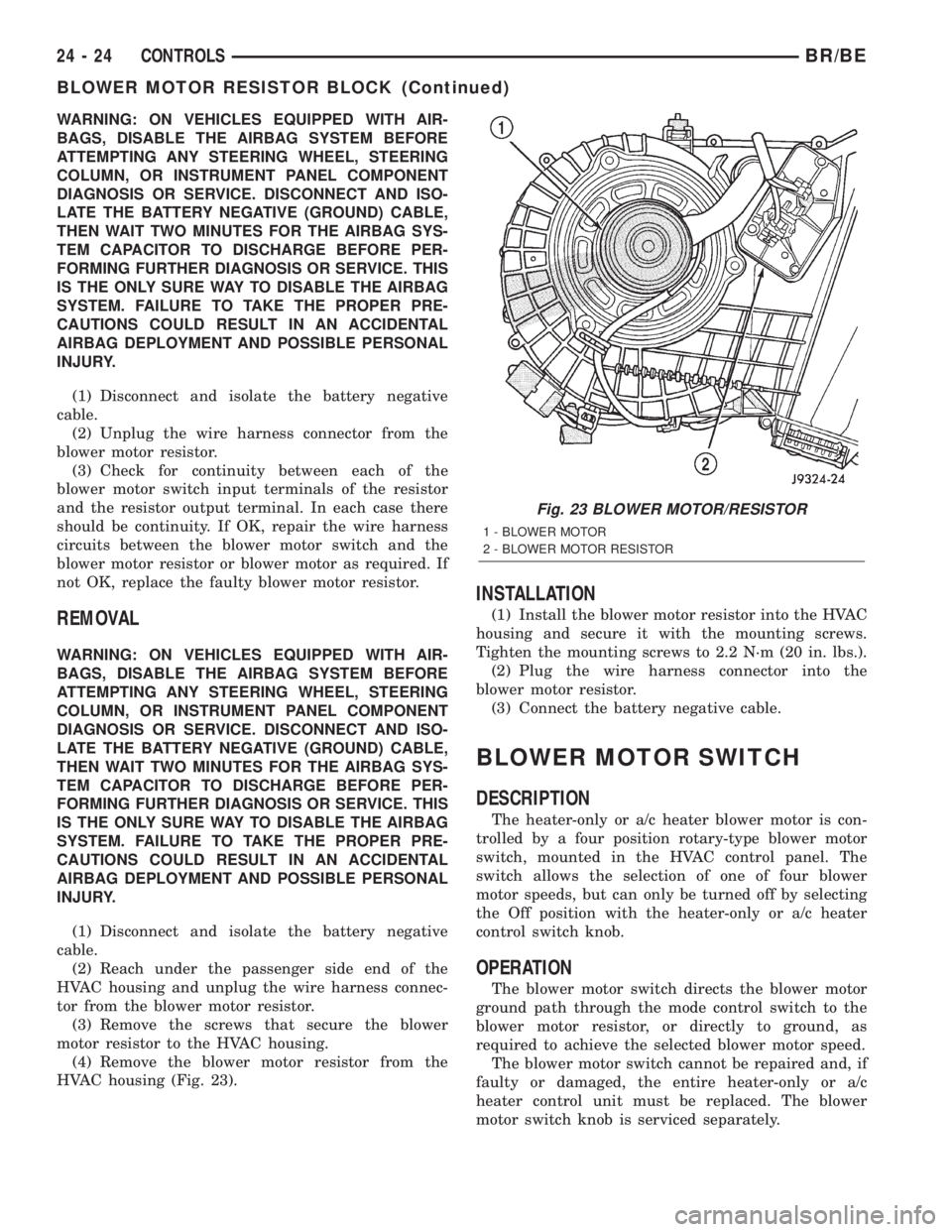
(2) Reach under the passenger side end of the
HVAC housing and unplug the wire harness connec-
tor from the blower motor resistor.
(3) Remove the screws that secure the blower
motor resistor to the HVAC housing.
(4) Remove the blower motor resistor from the
HVAC housing (Fig. 23).
INSTALLATION
(1) Install the blower motor resistor into the HVAC
housing and secure it with the mounting screws.
Tighten the mounting screws to 2.2 N´m (20 in. lbs.).
(2) Plug the wire harness connector into the
blower motor resistor.
(3) Connect the battery negative cable.
BLOWER MOTOR SWITCH
DESCRIPTION
The heater-only or a/c heater blower motor is con-
trolled by a four position rotary-type blower motor
switch, mounted in the HVAC control panel. The
switch allows the selection of one of four blower
motor speeds, but can only be turned off by selecting
the Off position with the heater-only or a/c heater
control switch knob.
OPERATION
The blower motor switch directs the blower motor
ground path through the mode control switch to the
blower motor resistor, or directly to ground, as
required to achieve the selected blower motor speed.
The blower motor switch cannot be repaired and, if
faulty or damaged, the entire heater-only or a/c
heater control unit must be replaced. The blower
motor switch knob is serviced separately.
Fig. 23 BLOWER MOTOR/RESISTOR
1 - BLOWER MOTOR
2 - BLOWER MOTOR RESISTOR
24 - 24 CONTROLSBR/BE
BLOWER MOTOR RESISTOR BLOCK (Continued)
Page 2146 of 2255
DIAGNOSIS AND TESTING - BLOWER MOTOR
SWITCH
For circuit descriptions and diagrams, (Refer to
Appropriate Wiring Information).
WARNING: ON VEHICLES EQUIPPED WITH AIR-
BAGS, DISABLE THE AIRBAG SYSTEM BEFORE
ATTEMPTING ANY STEERING WHEEL, STEERING
COLUMN, OR INSTRUMENT PANEL COMPONENT
DIAGNOSIS OR SERVICE. DISCONNECT AND ISO-
LATE THE BATTERY NEGATIVE (GROUND) CABLE,
THEN WAIT TWO MINUTES FOR THE AIRBAG SYS-
TEM CAPACITOR TO DISCHARGE BEFORE PER-
FORMING FURTHER DIAGNOSIS OR SERVICE. THIS
IS THE ONLY SURE WAY TO DISABLE THE AIRBAG
SYSTEM. FAILURE TO TAKE THE PROPER PRE-
CAUTIONS COULD RESULT IN AN ACCIDENTAL
AIRBAG DEPLOYMENT AND POSSIBLE PERSONAL
INJURY.
(1) Check for battery voltage at the fuse in the
Power Distribution Center (PDC). If OK, go to Step
2. If not OK, repair the shorted circuit or component
as required and replace the faulty fuse.
(2) Turn the ignition switch to the Off position.
Disconnect and isolate the battery negative cable.
Remove the a/c heater control from the instrument
panel. (Refer to 24 - HEATING & AIR CONDITION-
ING/CONTROLS/A/C HEATER CONTROL -
REMOVAL) Check for continuity between the ground
circuit cavity of the a/c heater control wire harness
connector and a good ground. There should be conti-
nuity. If OK, go to Step 3. If not OK, repair the open
circuit to ground as required.
(3) With the a/c heater control wire harness con-
nector unplugged, place the a/c heater mode control
switch knob in any position except the Off position.
Check for continuity between the ground circuit ter-
minal and each of the blower motor driver circuit ter-
minals of the a/c heater control as you move the
blower motor switch knob to each of the four speed
positions. There should be continuity at each driver
circuit terminal in only one blower motor switch
speed position. If OK, test and repair the blower
driver circuits between the a/c heater control connec-
tor and the blower motor resistor as required. If not
OK, replace the faulty a/c heater control unit.
REMOVAL
The blower motor switch cannot be repaired and, if
faulty or damaged, the entire heater-only or a/c
heater control unit must be replaced. (Refer to 24 -
HEATING & AIR CONDITIONING/CONTROLS/A/C
HEATER CONTROL - REMOVAL) The blower motor
switch knob is serviced separately.
BLEND DOOR ACTUATOR
REMOVAL
WARNING: ON VEHICLES EQUIPPED WITH AIR-
BAGS, DISABLE THE AIRBAG SYSTEM BEFORE
ATTEMPTING ANY STEERING WHEEL, STEERING
COLUMN, OR INSTRUMENT PANEL COMPONENT
DIAGNOSIS OR SERVICE. DISCONNECT AND ISO-
LATE THE BATTERY NEGATIVE (GROUND) CABLE,
THEN WAIT TWO MINUTES FOR THE AIRBAG SYS-
TEM CAPACITOR TO DISCHARGE BEFORE PER-
FORMING FURTHER DIAGNOSIS OR SERVICE. THIS
IS THE ONLY SURE WAY TO DISABLE THE AIRBAG
SYSTEM. FAILURE TO TAKE THE PROPER PRE-
CAUTIONS COULD RESULT IN AN ACCIDENTAL
AIRBAG DEPLOYMENT AND POSSIBLE PERSONAL
INJURY.
(1) Turn the ignition switch to the run position.
(2) Locate the temperature control knob in the mid
(12 o'clock) position.
(3) Turn the ignition switch to the off position.
(4) Disconnect and isolate the battery negative
cable.
(5) Remove the instrument panel from the vehi-
cle(Refer to 23 - BODY/INSTRUMENT PANEL/IN-
STRUMENT PANEL ASSEMBLY - REMOVAL).
(6) Remove the HVAC housing from the vehicle.
(Refer to 24 - HEATING & AIR CONDITIONING/
DISTRIBUTION/HVAC HOUSING - REMOVAL)
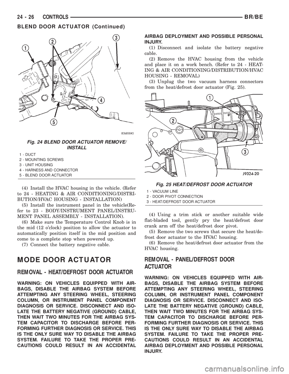
(7) Unplug the wire harness connector from the
blend door actuator (Fig. 24).
(8) Remove the two mounting screws which secure
the actuator to the housing.
(9) Slide the blend door actuator off the blend door
shaft.
NOTE: A black plastic coupler may be attached to
the blend door shaft. Remove the coupler and
inspect for damage. Reinstall if there is no damage
found.
INSTALLATION
NOTE: Before installing the blend door actuator, be
certain that the blend door is not binding and is
capable of full travel in both directions.
(1) Align the actuator with the blend door shaft
and rotate the actuator to align it to the mounting
bosses on the HVAC housing.
(2) Align and install the actuator screws. Tighten
the mounting screws to 2.2 N´m (20 in. lbs.).
(3) Plug in the wire harness connector to the blend
door actuator.
BR/BECONTROLS 24 - 25
BLOWER MOTOR SWITCH (Continued)
Page 2147 of 2255
(4) Install the HVAC housing in the vehicle. (Refer
to 24 - HEATING & AIR CONDITIONING/DISTRI-
BUTION/HVAC HOUSING - INSTALLATION)
(5) Install the instrument panel in the vehicle(Re-
fer to 23 - BODY/INSTRUMENT PANEL/INSTRU-
MENT PANEL ASSEMBLY - INSTALLATION).
(6) Make sure the Temperature Control Knob is in
the mid (12 o'clock) position to allow the actuator to
automatically position itself in the mid position and
come to a complete stop when powered up.
(7) Connect the battery negative cable.
MODE DOOR ACTUATOR
REMOVAL - HEAT/DEFROST DOOR ACTUATOR
WARNING: ON VEHICLES EQUIPPED WITH AIR-
BAGS, DISABLE THE AIRBAG SYSTEM BEFORE
ATTEMPTING ANY STEERING WHEEL, STEERING
COLUMN, OR INSTRUMENT PANEL COMPONENT
DIAGNOSIS OR SERVICE. DISCONNECT AND ISO-
LATE THE BATTERY NEGATIVE (GROUND) CABLE,
THEN WAIT TWO MINUTES FOR THE AIRBAG SYS-
TEM CAPACITOR TO DISCHARGE BEFORE PER-
FORMING FURTHER DIAGNOSIS OR SERVICE. THIS
IS THE ONLY SURE WAY TO DISABLE THE AIRBAG
SYSTEM. FAILURE TO TAKE THE PROPER PRE-
CAUTIONS COULD RESULT IN AN ACCIDENTALAIRBAG DEPLOYMENT AND POSSIBLE PERSONAL
INJURY.
(1) Disconnect and isolate the battery negative
cable.
(2) Remove the HVAC housing from the vehicle
and place it on a work bench. (Refer to 24 - HEAT-
ING & AIR CONDITIONING/DISTRIBUTION/HVAC
HOUSING - REMOVAL)
(3) Unplug the two vacuum harness connectors
from the heat/defrost door actuator (Fig. 25).
(4) Using a trim stick or another suitable wide
flat-bladed tool, gently pry the heat/defrost door
crank arm off the heat/defrost door pivot.
(5) Remove the two screws that secure the heat/de-
frost door actuator to the HVAC housing.
(6) Remove the heat/defrost door actuator from the
HVAC housing.
REMOVAL - PANEL/DEFROST DOOR
ACTUATOR
WARNING: ON VEHICLES EQUIPPED WITH AIR-
BAGS, DISABLE THE AIRBAG SYSTEM BEFORE
ATTEMPTING ANY STEERING WHEEL, STEERING
COLUMN, OR INSTRUMENT PANEL COMPONENT
DIAGNOSIS OR SERVICE. DISCONNECT AND ISO-
LATE THE BATTERY NEGATIVE (GROUND) CABLE,
THEN WAIT TWO MINUTES FOR THE AIRBAG SYS-
TEM CAPACITOR TO DISCHARGE BEFORE PER-
FORMING FURTHER DIAGNOSIS OR SERVICE. THIS
IS THE ONLY SURE WAY TO DISABLE THE AIRBAG
SYSTEM. FAILURE TO TAKE THE PROPER PRE-
CAUTIONS COULD RESULT IN AN ACCIDENTAL
AIRBAG DEPLOYMENT AND POSSIBLE PERSONAL
INJURY.
Fig. 24 BLEND DOOR ACTUATOR REMOVE/
INSTALL
1 - DUCT
2 - MOUNTING SCREWS
3 - UNIT HOUSING
4 - HARNESS AND CONNECTOR
5 - BLEND DOOR ACTUATOR
Fig. 25 HEAT/DEFROST DOOR ACTUATOR
1 - VACUUM LINE
2 - DOOR PIVOT CONNECTION
3 - HEAT/DEFROST DOOR ACTUATOR
24 - 26 CONTROLSBR/BE
BLEND DOOR ACTUATOR (Continued)
Page 2152 of 2255
AIR OUTLETS
REMOVAL - DEMISTER GRILLES
(1) Using a trim stick or another suitable wide
flat-bladed tool, gently pry at the perimeter edges of
the demister grille to release the snap features from
the instrument panel top cover.
(2) Remove the demister grille from the instru-
ment panel.
REMOVAL - PANEL OUTLET BARRELS
WARNING: THE PANEL OUTLET BARRELS
INSTALLED IN THE PASSENGER SIDE AIRBAG
DOOR PANEL OUTLET HOUSINGS MUST NEVER
BE REINSTALLED FOLLOWING REMOVAL FOR ANY
REASON. THEY MUST BE REPLACED WITH NEW
BARRELS. FAILURE TO OBSERVE THIS WARNING
COULD RESULT IN OCCUPANT INJURIES UPON
AIRBAG DEPLOYMENT.
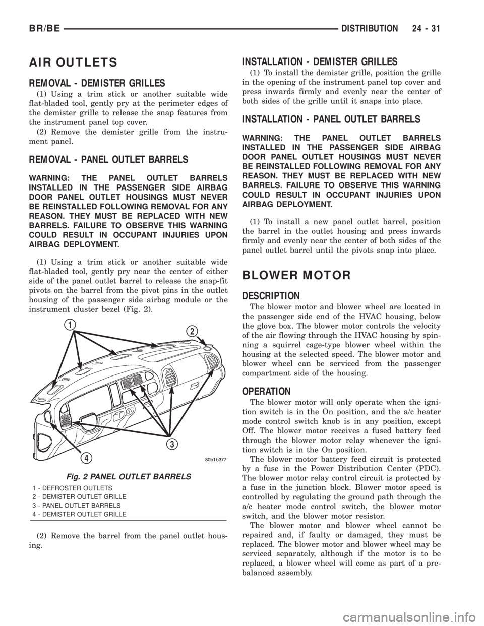
(1) Using a trim stick or another suitable wide
flat-bladed tool, gently pry near the center of either
side of the panel outlet barrel to release the snap-fit
pivots on the barrel from the pivot pins in the outlet
housing of the passenger side airbag module or the
instrument cluster bezel (Fig. 2).
(2) Remove the barrel from the panel outlet hous-
ing.
INSTALLATION - DEMISTER GRILLES
(1) To install the demister grille, position the grille
in the opening of the instrument panel top cover and
press inwards firmly and evenly near the center of
both sides of the grille until it snaps into place.
INSTALLATION - PANEL OUTLET BARRELS
WARNING: THE PANEL OUTLET BARRELS
INSTALLED IN THE PASSENGER SIDE AIRBAG
DOOR PANEL OUTLET HOUSINGS MUST NEVER
BE REINSTALLED FOLLOWING REMOVAL FOR ANY
REASON. THEY MUST BE REPLACED WITH NEW
BARRELS. FAILURE TO OBSERVE THIS WARNING
COULD RESULT IN OCCUPANT INJURIES UPON
AIRBAG DEPLOYMENT.
(1) To install a new panel outlet barrel, position
the barrel in the outlet housing and press inwards
firmly and evenly near the center of both sides of the
panel outlet barrel until the pivots snap into place.
BLOWER MOTOR
DESCRIPTION
The blower motor and blower wheel are located in
the passenger side end of the HVAC housing, below
the glove box. The blower motor controls the velocity
of the air flowing through the HVAC housing by spin-
ning a squirrel cage-type blower wheel within the
housing at the selected speed. The blower motor and
blower wheel can be serviced from the passenger
compartment side of the housing.
OPERATION
The blower motor will only operate when the igni-
tion switch is in the On position, and the a/c heater
mode control switch knob is in any position, except
Off. The blower motor receives a fused battery feed
through the blower motor relay whenever the igni-
tion switch is in the On position.
The blower motor battery feed circuit is protected
by a fuse in the Power Distribution Center (PDC).
The blower motor relay control circuit is protected by
a fuse in the junction block. Blower motor speed is
controlled by regulating the ground path through the
a/c heater mode control switch, the blower motor
switch, and the blower motor resistor.
The blower motor and blower wheel cannot be
repaired and, if faulty or damaged, they must be
replaced. The blower motor and blower wheel may be
serviced separately, although if the motor is to be
replaced, a blower wheel will come as part of a pre-
balanced assembly.
Fig. 2 PANEL OUTLET BARRELS
1 - DEFROSTER OUTLETS
2 - DEMISTER OUTLET GRILLE
3 - PANEL OUTLET BARRELS
4 - DEMISTER OUTLET GRILLE
BR/BEDISTRIBUTION 24 - 31
Page 2161 of 2255
PLUMBING
TABLE OF CONTENTS
page page
PLUMBING
DESCRIPTION..........................40
OPERATION............................41
WARNING..............................42
CAUTION..............................42
DIAGNOSIS AND TESTING
DIAGNOSIS AND TESTING - REFRIGERANT
SYSTEM LEAKS.......................43
STANDARD PROCEDURE
STANDARD PROCEDURE - A/C LINE
COUPLERS...........................44
STANDARD PROCEDURE - REFRIGERANT
SYSTEM SERVICE EQUIPMENT...........45
STANDARD PROCEDURE - REFRIGERANT
RECOVERY...........................45
STANDARD PROCEDURE - REFRIGERANT
SYSTEM EVACUATE....................46
STANDARD PROCEDURE - REFRIGERANT
SYSTEM CHARGE......................46
SPECIFICATIONS........................46
A/C COMPRESSOR
DESCRIPTION..........................46
OPERATION............................46
DIAGNOSIS AND TESTING
DIAGNOSIS AND TESTING - A/C
COMPRESSOR........................47
REMOVAL..............................47
INSTALLATION..........................48
A/C CONDENSER
DESCRIPTION..........................49
OPERATION............................49
REMOVAL..............................49
INSTALLATION..........................50
SUCTION AND DISCHARGE LINE
REMOVAL..............................51
INSTALLATION..........................52LIQUID LINE
REMOVAL..............................52
INSTALLATION..........................52
A/C EVAPORATOR
DESCRIPTION..........................53
OPERATION............................53
REMOVAL..............................53
INSTALLATION..........................53
A/C ORIFICE TUBE
DESCRIPTION..........................54
OPERATION............................54
DIAGNOSIS AND TESTING
DIAGNOSIS AND TESTING - FIXED
ORIFICE TUBE.........................54
REMOVAL..............................54
INSTALLATION..........................54
ACCUMULATOR
DESCRIPTION..........................55
OPERATION............................55
REMOVAL..............................55
INSTALLATION..........................55
HEATER CORE
DESCRIPTION..........................56
OPERATION............................56
REMOVAL..............................56
INSTALLATION..........................56
REFRIGERANT
DESCRIPTION..........................56
OPERATION............................57
REFRIGERANT OIL
DESCRIPTION..........................57
OPERATION............................57
STANDARD PROCEDURE
STANDARD PROCEDURE - REFRIGERANT
OIL LEVEL............................57
PLUMBING
DESCRIPTION - A/C LINE COUPLERS
Spring-lock type refrigerant line couplers are used
to connect many of the refrigerant lines and other
components to the refrigerant system. These couplers
require a special tool for disengaging the two coupler
halves.
DESCRIPTION- REFRIGERANT LINES
The refrigerant lines and hoses are used to carry
the refrigerant between the various air conditioning
system components. A barrier hose design with a
nylon tube, which is sandwiched between rubber lay-
ers, is used for the R-134a air conditioning system on
this vehicle. This nylon tube helps to further contain
the R-134a refrigerant, which has a smaller molecu-
lar structure than R-12 refrigerant. The ends of the
refrigerant hoses are made from lightweight alumi-
num or steel, and commonly use braze-less fittings.
24 - 40 PLUMBINGBR/BE
Page 2162 of 2255
Any kinks or sharp bends in the refrigerant plumb-
ing will reduce the capacity of the entire air condi-
tioning system. Kinks and sharp bends reduce the
flow of refrigerant in the system. A good rule for the
flexible hose refrigerant lines is to keep the radius of
all bends at least ten times the diameter of the hose.
In addition, the flexible hose refrigerant lines should
be routed so they are at least 80 millimeters (3
inches) from the exhaust manifold.
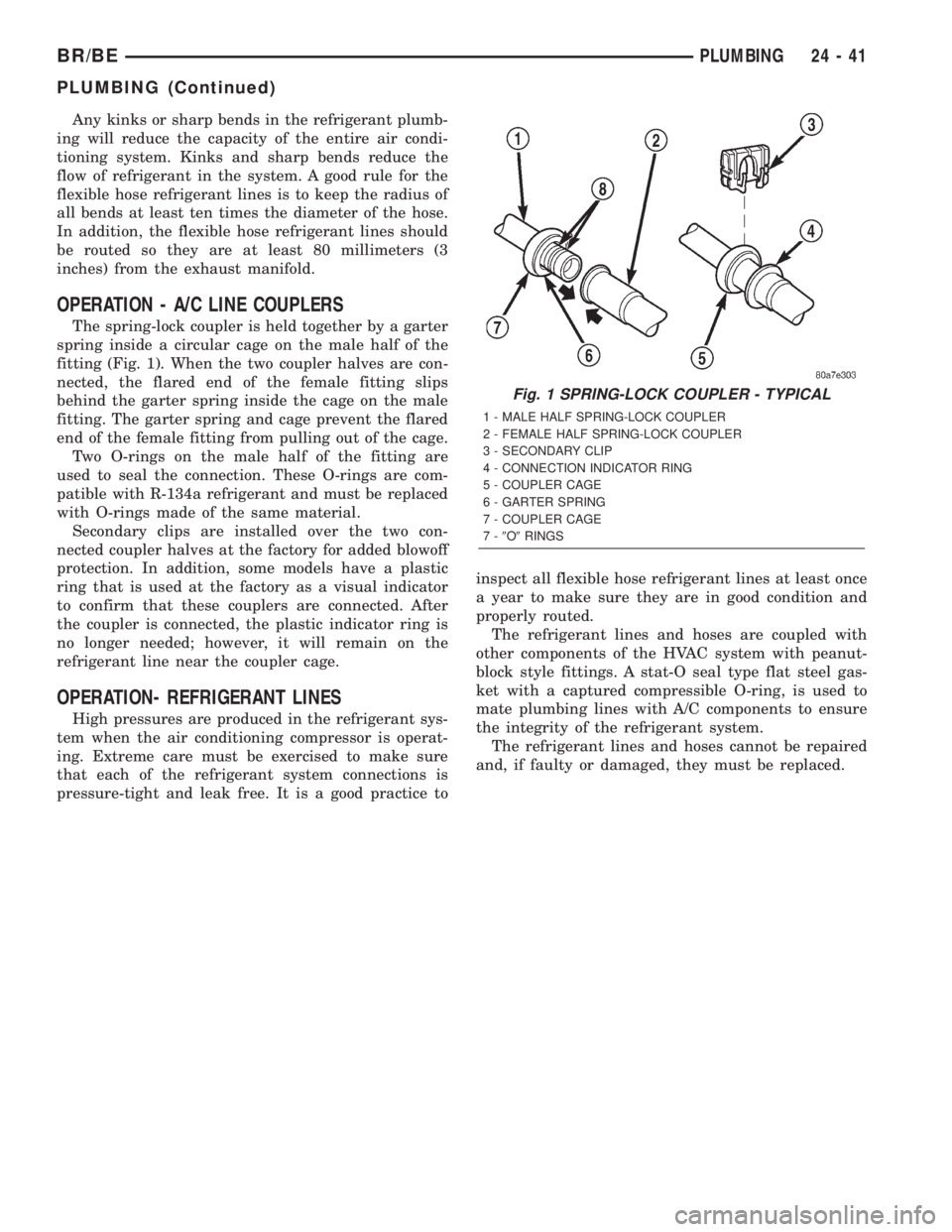
OPERATION - A/C LINE COUPLERS
The spring-lock coupler is held together by a garter
spring inside a circular cage on the male half of the
fitting (Fig. 1). When the two coupler halves are con-
nected, the flared end of the female fitting slips
behind the garter spring inside the cage on the male
fitting. The garter spring and cage prevent the flared
end of the female fitting from pulling out of the cage.
Two O-rings on the male half of the fitting are
used to seal the connection. These O-rings are com-
patible with R-134a refrigerant and must be replaced
with O-rings made of the same material.
Secondary clips are installed over the two con-
nected coupler halves at the factory for added blowoff
protection. In addition, some models have a plastic
ring that is used at the factory as a visual indicator
to confirm that these couplers are connected. After
the coupler is connected, the plastic indicator ring is
no longer needed; however, it will remain on the
refrigerant line near the coupler cage.
OPERATION- REFRIGERANT LINES
High pressures are produced in the refrigerant sys-
tem when the air conditioning compressor is operat-
ing. Extreme care must be exercised to make sure
that each of the refrigerant system connections is
pressure-tight and leak free. It is a good practice toinspect all flexible hose refrigerant lines at least once
a year to make sure they are in good condition and
properly routed.
The refrigerant lines and hoses are coupled with
other components of the HVAC system with peanut-
block style fittings. A stat-O seal type flat steel gas-
ket with a captured compressible O-ring, is used to
mate plumbing lines with A/C components to ensure
the integrity of the refrigerant system.
The refrigerant lines and hoses cannot be repaired
and, if faulty or damaged, they must be replaced.
Fig. 1 SPRING-LOCK COUPLER - TYPICAL
1 - MALE HALF SPRING-LOCK COUPLER
2 - FEMALE HALF SPRING-LOCK COUPLER
3 - SECONDARY CLIP
4 - CONNECTION INDICATOR RING
5 - COUPLER CAGE
6 - GARTER SPRING
7 - COUPLER CAGE
7-9O9RINGS
BR/BEPLUMBING 24 - 41
PLUMBING (Continued)
Page 2163 of 2255
SERVICE WARNINGS
WARNING:
THE AIR CONDITIONING SYSTEM CONTAINS
REFRIGERANT UNDER HIGH PRESSURE. SEVERE
PERSONAL INJURY MAY RESULT FROM IMPROPER
SERVICE PROCEDURES. REPAIRS SHOULD ONLY
BE PERFORMED BY QUALIFIED SERVICE PERSON-
NEL.
AVOID BREATHING THE REFRIGERANT AND
REFRIGERANT OIL VAPOR OR MIST. EXPOSURE
MAY IRRITATE THE EYES, NOSE, AND/OR THROAT.
WEAR EYE PROTECTION WHEN SERVICING THE
AIR CONDITIONING REFRIGERANT SYSTEM. SERI-
OUS EYE INJURY CAN RESULT FROM DIRECT
CONTACT WITH THE REFRIGERANT. IF EYE CON-
TACT OCCURS, SEEK MEDICAL ATTENTION IMME-
DIATELY.
DO NOT EXPOSE THE REFRIGERANT TO OPEN
FLAME. POISONOUS GAS IS CREATED WHEN
REFRIGERANT IS BURNED. AN ELECTRONIC LEAK
DETECTOR IS RECOMMENDED.
IF ACCIDENTAL SYSTEM DISCHARGE OCCURS,
VENTILATE THE WORK AREA BEFORE RESUMING
SERVICE. LARGE AMOUNTS OF REFRIGERANT
RELEASED IN A CLOSED WORK AREA WILL DIS-
PLACE THE OXYGEN AND CAUSE SUFFOCATION.
THE EVAPORATION RATE OF R-134a REFRIGER-
ANT AT AVERAGE TEMPERATURE AND ALTITUDE
IS EXTREMELY HIGH. AS A RESULT, ANYTHING
THAT COMES IN CONTACT WITH THE REFRIGER-
ANT WILL FREEZE. ALWAYS PROTECT THE SKIN
OR DELICATE OBJECTS FROM DIRECT CONTACT
WITH THE REFRIGERANT.
THE R-134a SERVICE EQUIPMENT OR THE VEHI-
CLE REFRIGERANT SYSTEM SHOULD NOT BE
PRESSURE TESTED OR LEAK TESTED WITH COM-
PRESSED AIR. SOME MIXTURES OF AIR AND
R-134a HAVE BEEN SHOWN TO BE COMBUSTIBLE
AT ELEVATED PRESSURES. THESE MIXTURES ARE
POTENTIALLY DANGEROUS, AND MAY RESULT IN
FIRE OR EXPLOSION CAUSING INJURY OR PROP-
ERTY DAMAGE.
SERVICE CAUTIONS
CAUTION: Liquid refrigerant is corrosive to metal
surfaces. Follow the operating instructions supplied
with the service equipment being used.
Never add R-12 to a refrigerant system designed to
use R-134a. Damage to the system will result.
R-12 refrigerant oil must not be mixed with R-134a
refrigerant oil. They are not compatible.
Do not use R-12 equipment or parts on the R-134a
system. Damage to the system will result.Do not overcharge the refrigerant system. This will
cause excessive compressor head pressure and
can cause noise and system failure.
Recover the refrigerant before opening any fitting
or connection. Open the fittings with caution, even
after the system has been discharged. Never open
or loosen a connection before recovering the refrig-
erant.
Do not remove the secondary retention clip from
any spring-lock coupler connection while the refrig-
erant system is under pressure. Recover the refrig-
erant before removing the secondary retention clip.
Open the fittings with caution, even after the sys-
tem has been discharged. Never open or loosen a
connection before recovering the refrigerant.
The refrigerant system must always be evacuated
before charging.
Do not open the refrigerant system or uncap a
replacement component until you are ready to ser-
vice the system. This will prevent contamination in
the system.
Before disconnecting a component, clean the out-
side of the fittings thoroughly to prevent contami-
nation from entering the refrigerant system.
Immediately after disconnecting a component from
the refrigerant system, seal the open fittings with a
cap or plug.
Before connecting an open refrigerant fitting,
always install a new seal or gasket. Coat the fitting
and seal with clean refrigerant oil before connect-
ing.
Do not remove the sealing caps from a replacement
component until it is to be installed.
When installing a refrigerant line, avoid sharp
bends that may restrict refrigerant flow. Position the
refrigerant lines away from exhaust system compo-
nents or any sharp edges, which may damage the
line.
Tighten refrigerant fittings only to the specified
torque. The aluminum fittings used in the refriger-
ant system will not tolerate overtightening.
When disconnecting a refrigerant fitting, use a
wrench on both halves of the fitting. This will pre-
vent twisting of the refrigerant lines or tubes.
Refrigerant oil will absorb moisture from the atmo-
sphere if left uncapped. Do not open a container of
refrigerant oil until you are ready to use it. Replace
the cap on the oil container immediately after using.
Store refrigerant oil only in a clean, airtight, and
moisture-free container.
Keep service tools and the work area clean. Con-
tamination of the refrigerant system through care-
less work habits must be avoided.
24 - 42 PLUMBINGBR/BE
PLUMBING (Continued)
Page 2165 of 2255
tor probe should be moved slowly along the bottom
side of all refrigerant lines, connector fittings and
components.
(5) To inspect the evaporator for leaks, insert the
electronic leak detector probe into the center instru-
ment panel outlet. Set the blower motor switch to the
lowest speed position, and the mode control switch in
the recirculation mode.
SYSTEM LOW
(1) Position the vehicle in a wind-free work area.
This will aid in detecting small leaks.
(2) Bring the refrigerant system up to operating
temperature and pressure. This is done by allowing
the engine to run with the air conditioning system
turned on for five minutes.
(3) With the engine not running, use a electronic
R-134a leak detector and search for leaks. Because
R-134a refrigerant is heavier than air, the leak detec-
tor probe should be moved slowly along the bottom
side of all refrigerant lines, connector fittings and
components.
(4) To inspect the evaporator coil for leaks, insert
the electronic leak detector probe into the center
instrument panel outlet. Set the blower motor switch
to the lowest speed position, and the mode control
switch in the recirculation mode.
STANDARD PROCEDURE - A/C LINE
COUPLERS
WARNING: REVIEW THE WARNINGS AND CAU-
TIONS IN THE FRONT OF THIS SECTION BEFORE
PERFORMING THE FOLLOWING OPERATION.
(Refer to 24 - HEATING & AIR CONDITIONING/
PLUMBING - WARNING) (Refer to 24 - HEATING &
AIR CONDITIONING/PLUMBING - CAUTION)
REMOVAL
(1) Recover the refrigerant from the refrigerant
system. (Refer to 24 - HEATING & AIR CONDI-
TIONING/PLUMBING - STANDARD PROCEDURE -
REFRIGERANT RECOVERY)
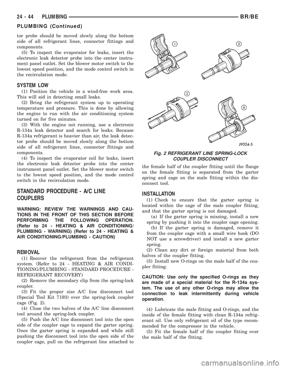
(2) Remove the secondary clip from the spring-lock
coupler.
(3) Fit the proper size A/C line disconnect tool
(Special Tool Kit 7193) over the spring-lock coupler
cage (Fig. 2).
(4) Close the two halves of the A/C line disconnect
tool around the spring-lock coupler.
(5) Push the A/C line disconnect tool into the open
side of the coupler cage to expand the garter spring.
Once the garter spring is expanded and while still
pushing the disconnect tool into the open side of the
coupler cage, pull on the refrigerant line attached tothe female half of the coupler fitting until the flange
on the female fitting is separated from the garter
spring and cage on the male fitting within the dis-
connect tool.
INSTALLATION
(1) Check to ensure that the garter spring is
located within the cage of the male coupler fitting,
and that the garter spring is not damaged.
(a) If the garter spring is missing, install a new
spring by pushing it into the coupler cage opening.
(b) If the garter spring is damaged, remove it
from the coupler cage with a small wire hook (DO
NOT use a screwdriver) and install a new garter
spring.
(2) Clean any dirt or foreign material from both
halves of the coupler fitting.
(3) Install new O-rings on the male half of the cou-
pler fitting.
CAUTION: Use only the specified O-rings as they
are made of a special material for the R-134a sys-
tem. The use of any other O-rings may allow the
connection to leak intermittently during vehicle
operation.
(4) Lubricate the male fitting and O-rings, and the
inside of the female fitting with clean R-134a refrig-
erant oil. Use only refrigerant oil of the type recom-
mended for the compressor in the vehicle.
(5) Fit the female half of the coupler fitting over
the male half of the fitting.
Fig. 2 REFRIGERANT LINE SPRING-LOCK
COUPLER DISCONNECT
24 - 44 PLUMBINGBR/BE
PLUMBING (Continued)