2002 DODGE RAM lock
[x] Cancel search: lockPage 2166 of 2255
(6) Push together firmly on the two halves of the
coupler fitting until the garter spring in the cage on
the male half of the fitting snaps over the flanged
end on the female half of the fitting.
(7) Ensure that the spring-lock coupler is fully
engaged by trying to separate the two coupler halves.
This is done by pulling the refrigerant lines on either
side of the coupler away from each other.
(8) Reinstall the secondary clip over the spring-
lock coupler cage.
STANDARD PROCEDURE - REFRIGERANT
SYSTEM SERVICE EQUIPMENT
WARNING: REVIEW THE WARNINGS AND CAU-
TIONS IN THE FRONT OF THIS SECTION BEFORE
PERFORMING THE FOLLOWING OPERATION.
(Refer to 24 - HEATING & AIR CONDITIONING/
PLUMBING - WARNING) (Refer to 24 - HEATING &
AIR CONDITIONING/PLUMBING - CAUTION)
When servicing the air conditioning system, a
R-134a refrigerant recovery/recycling/charging sta-
tion that meets SAE Standard J2210 must be used.
Contact an automotive service equipment supplier for
refrigerant recovery/recycling/charging equipment.
Refer to the operating instructions supplied by the
equipment manufacturer for proper care and use of
this equipment.
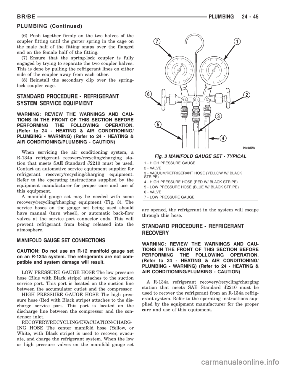
A manifold gauge set may be needed with some
recovery/recycling/charging equipment (Fig. 3). The
service hoses on the gauge set being used should
have manual (turn wheel), or automatic back-flow
valves at the service port connector ends. This will
prevent refrigerant from being released into the
atmosphere.
MANIFOLD GAUGE SET CONNECTIONS
CAUTION: Do not use an R-12 manifold gauge set
on an R-134a system. The refrigerants are not com-
patible and system damage will result.
LOW PRESSURE GAUGE HOSE The low pressure
hose (Blue with Black stripe) attaches to the suction
service port. This port is located on the suction line
between the accumulator outlet and the compressor.
HIGH PRESSURE GAUGE HOSE The high pres-
sure hose (Red with Black stripe) attaches to the dis-
charge service port. This port is located on the
discharge line between the compressor and the con-
denser inlet.
RECOVERY/RECYCLING/EVACUATION/CHARG-
ING HOSE The center manifold hose (Yellow, or
White, with Black stripe) is used to recover, evacu-
ate, and charge the refrigerant system. When the low
or high pressure valves on the manifold gauge setare opened, the refrigerant in the system will escape
through this hose.
STANDARD PROCEDURE - REFRIGERANT
RECOVERY
WARNING: REVIEW THE WARNINGS AND CAU-
TIONS IN THE FRONT OF THIS SECTION BEFORE
PERFORMING THE FOLLOWING OPERATION.
(Refer to 24 - HEATING & AIR CONDITIONING/
PLUMBING - WARNING) (Refer to 24 - HEATING &
AIR CONDITIONING/PLUMBING - CAUTION)
A R-134a refrigerant recovery/recycling/charging
station that meets SAE Standard J2210 must be
used to recover the refrigerant from an R-134a refrig-
erant system. Refer to the operating instructions sup-
plied by the equipment manufacturer for the proper
care and use of this equipment.
Fig. 3 MANIFOLD GAUGE SET - TYPICAL
1 - HIGH PRESSURE GAUGE
2 - VALVE
3 - VACUUM/REFRIGERANT HOSE (YELLOW W/ BLACK
STRIPE)
4 - HIGH PRESSURE HOSE (RED W/ BLACK STRIPE)
5 - LOW PRESSURE HOSE (BLUE W/ BLACK STRIPE)
6 - VALVE
7 - LOW PRESSURE GAUGE
BR/BEPLUMBING 24 - 45
PLUMBING (Continued)
Page 2170 of 2255
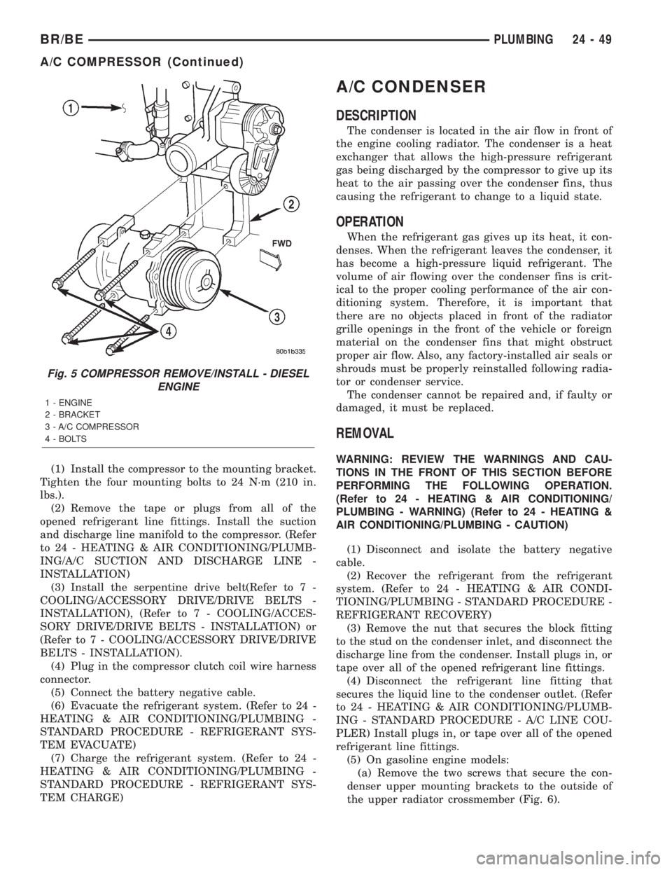
(1) Install the compressor to the mounting bracket.
Tighten the four mounting bolts to 24 N´m (210 in.
lbs.).
(2) Remove the tape or plugs from all of the
opened refrigerant line fittings. Install the suction
and discharge line manifold to the compressor. (Refer
to 24 - HEATING & AIR CONDITIONING/PLUMB-
ING/A/C SUCTION AND DISCHARGE LINE -
INSTALLATION)
(3) Install the serpentine drive belt(Refer to 7 -
COOLING/ACCESSORY DRIVE/DRIVE BELTS -
INSTALLATION), (Refer to 7 - COOLING/ACCES-
SORY DRIVE/DRIVE BELTS - INSTALLATION) or
(Refer to 7 - COOLING/ACCESSORY DRIVE/DRIVE
BELTS - INSTALLATION).
(4) Plug in the compressor clutch coil wire harness
connector.
(5) Connect the battery negative cable.
(6) Evacuate the refrigerant system. (Refer to 24 -
HEATING & AIR CONDITIONING/PLUMBING -
STANDARD PROCEDURE - REFRIGERANT SYS-
TEM EVACUATE)
(7) Charge the refrigerant system. (Refer to 24 -
HEATING & AIR CONDITIONING/PLUMBING -
STANDARD PROCEDURE - REFRIGERANT SYS-
TEM CHARGE)
A/C CONDENSER
DESCRIPTION
The condenser is located in the air flow in front of
the engine cooling radiator. The condenser is a heat
exchanger that allows the high-pressure refrigerant
gas being discharged by the compressor to give up its
heat to the air passing over the condenser fins, thus
causing the refrigerant to change to a liquid state.
OPERATION
When the refrigerant gas gives up its heat, it con-
denses. When the refrigerant leaves the condenser, it
has become a high-pressure liquid refrigerant. The
volume of air flowing over the condenser fins is crit-
ical to the proper cooling performance of the air con-
ditioning system. Therefore, it is important that
there are no objects placed in front of the radiator
grille openings in the front of the vehicle or foreign
material on the condenser fins that might obstruct
proper air flow. Also, any factory-installed air seals or
shrouds must be properly reinstalled following radia-
tor or condenser service.
The condenser cannot be repaired and, if faulty or
damaged, it must be replaced.
REMOVAL
WARNING: REVIEW THE WARNINGS AND CAU-
TIONS IN THE FRONT OF THIS SECTION BEFORE
PERFORMING THE FOLLOWING OPERATION.
(Refer to 24 - HEATING & AIR CONDITIONING/
PLUMBING - WARNING) (Refer to 24 - HEATING &
AIR CONDITIONING/PLUMBING - CAUTION)
(1) Disconnect and isolate the battery negative
cable.
(2) Recover the refrigerant from the refrigerant
system. (Refer to 24 - HEATING & AIR CONDI-
TIONING/PLUMBING - STANDARD PROCEDURE -
REFRIGERANT RECOVERY)
(3) Remove the nut that secures the block fitting
to the stud on the condenser inlet, and disconnect the
discharge line from the condenser. Install plugs in, or
tape over all of the opened refrigerant line fittings.
(4) Disconnect the refrigerant line fitting that
secures the liquid line to the condenser outlet. (Refer
to 24 - HEATING & AIR CONDITIONING/PLUMB-
ING - STANDARD PROCEDURE - A/C LINE COU-
PLER) Install plugs in, or tape over all of the opened
refrigerant line fittings.
(5) On gasoline engine models:
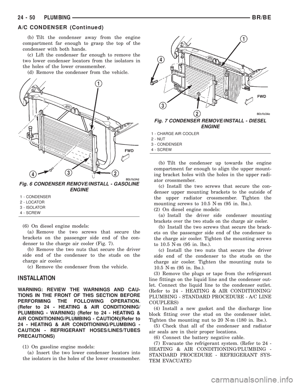
(a) Remove the two screws that secure the con-
denser upper mounting brackets to the outside of
the upper radiator crossmember (Fig. 6).
Fig. 5 COMPRESSOR REMOVE/INSTALL - DIESEL
ENGINE
1 - ENGINE
2 - BRACKET
3 - A/C COMPRESSOR
4 - BOLTS
BR/BEPLUMBING 24 - 49
A/C COMPRESSOR (Continued)
Page 2171 of 2255
(b) Tilt the condenser away from the engine
compartment far enough to grasp the top of the
condenser with both hands.
(c) Lift the condenser far enough to remove the
two lower condenser locators from the isolators in
the holes of the lower crossmember.
(d) Remove the condenser from the vehicle.
(6) On diesel engine models:
(a) Remove the two screws that secure the
brackets on the passenger side end of the con-
denser to the charge air cooler (Fig. 7).
(b) Remove the two nuts that secure the driver
side end of the condenser to the studs on the
charge air cooler.
(c) Remove the condenser from the vehicle.
INSTALLATION
WARNING: REVIEW THE WARNINGS AND CAU-
TIONS IN THE FRONT OF THIS SECTION BEFORE
PERFORMING THE FOLLOWING OPERATION.
(Refer to 24 - HEATING & AIR CONDITIONING/
PLUMBING - WARNING) (Refer to 24 - HEATING &
AIR CONDITIONING/PLUMBING - CAUTION)(Refer to
24 - HEATING & AIR CONDITIONING/PLUMBING -
CAUTION - REFRIGERANT HOSES/LINES/TUBES
PRECAUTIONS)
(1) On gasoline engine models:
(a) Insert the two lower condenser locators into
the isolators in the holes of the lower crossmember.(b) Tilt the condenser up towards the engine
compartment far enough to align the upper mount-
ing bracket holes with the holes in the upper radi-
ator crossmember.
(c) Install the two screws that secure the con-
denser upper mounting brackets to the outside of
the upper radiator crossmember. Tighten the
mounting screws to 10.5 N´m (95 in. lbs.).
(2) On diesel engine models:
(a)
Install the driver side condenser mounting
brackets over the two studs on the charge air cooler.
(b) Install the two screws that secure the brack-
ets on the passenger side end of the condenser to
the charge air cooler. Tighten the mounting screws
to 10.5 N´m (95 in. lbs.).
(c) Install the two nuts that secure the driver
side end of the condenser to the studs on the
charge air cooler. Tighten the mounting nuts to
10.5 N´m (95 in. lbs.).
(3) Remove the plugs or tape from the refrigerant
line fittings on the liquid line and the condenser out-
let. Connect the liquid line to the condenser outlet.
(Refer to 24 - HEATING & AIR CONDITIONING/
PLUMBING - STANDARD PROCEDURE - A/C LINE
COUPLERS)
(4) Install a new gasket and the discharge line
block fitting over the stud on the condenser inlet.
Tighten the mounting nut to 20 N´m (180 in. lbs.).
(5) Check that all of the condenser and radiator
air seals are in their proper locations.
(6) Connect the battery negative cable.
(7) Evacuate the refrigerant system. (Refer to 24 -
HEATING & AIR CONDITIONING/PLUMBING -
STANDARD PROCEDURE - REFRIGERANT SYS-
TEM EVACUATE)
Fig. 6 CONDENSER REMOVE/INSTALL - GASOLINE
ENGINE
1 - CONDENSER
2 - LOCATOR
3 - ISOLATOR
4 - SCREW
Fig. 7 CONDENSER REMOVE/INSTALL - DIESEL
ENGINE
1 - CHARGE AIR COOLER
2 - NUT
3 - CONDENSER
4 - SCREW
24 - 50 PLUMBINGBR/BE
A/C CONDENSER (Continued)
Page 2172 of 2255
(8) Charge the refrigerant system. (Refer to 24 -
HEATING & AIR CONDITIONING/PLUMBING -
STANDARD PROCEDURE - REFRIGERANT SYS-
TEM CHARGE)
NOTE: If the condenser is replaced, add 30 millili-
ters (1 fluid ounce) of refrigerant oil to the refriger-
ant system. Use only refrigerant oil of the type
recommended for the compressor in the vehicle.
(Refer to 24 - HEATING & AIR CONDITIONING/
PLUMBING/REFRIGERANT OIL - DESCRIPTION)
SUCTION AND DISCHARGE
LINE
REMOVAL
WARNING: REVIEW THE WARNINGS AND CAU-
TIONS IN THE FRONT OF THIS SECTION BEFORE
PERFORMING THE FOLLOWING OPERATION.
(Refer to 24 - HEATING & AIR CONDITIONING/
PLUMBING - WARNING) (Refer to 24 - HEATING &
AIR CONDITIONING/PLUMBING - CAUTION)(1) Disconnect and isolate the battery negative
cable.
(2) Recover the refrigerant from the refrigerant
system. (Refer to 24 - HEATING & AIR CONDI-
TIONING/PLUMBING - STANDARD PROCEDURE -
REFRIGERANT RECOVERY)
(3) Unplug the wire harness connector from the a/c
high pressure switch.
(4) Disconnect the suction line refrigerant line cou-
pler at the accumulator. (Refer to 24 - HEATING &
AIR CONDITIONING/PLUMBING - STANDARD
PROCEDURE - A/C LINE COUPLER) Install plugs
in, or tape over all of the opened refrigerant line fit-
tings.
(5) Remove the nut that secures the block fitting
to the stud on the condenser inlet and disconnect the
discharge line from the condenser. Install plugs in, or
tape over all of the opened refrigerant line fittings.
(6) On models with a gasoline engine, remove the
nut that secures the refrigerant line support bracket
to the stud on the compressor mounting bracket.
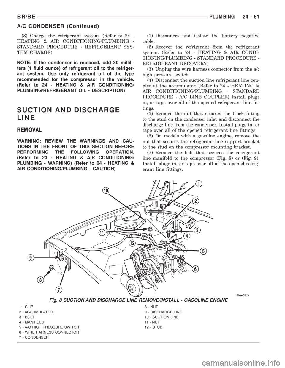
(7) Remove the bolt that secures the refrigerant
line manifold to the compressor (Fig. 8) or (Fig. 9).
Install plugs in, or tape over all of the opened refrig-
erant line fittings.
Fig. 8 SUCTION AND DISCHARGE LINE REMOVE/INSTALL - GASOLINE ENGINE
1 - CLIP
2 - ACCUMULATOR
3 - BOLT
4 - MANIFOLD
5 - A/C HIGH PRESSURE SWITCH
6 - WIRE HARNESS CONNECTOR
7 - CONDENSER8 - NUT
9 - DISCHARGE LINE
10 - SUCTION LINE
11 - NUT
12 - STUD
BR/BEPLUMBING 24 - 51
A/C CONDENSER (Continued)
Page 2173 of 2255
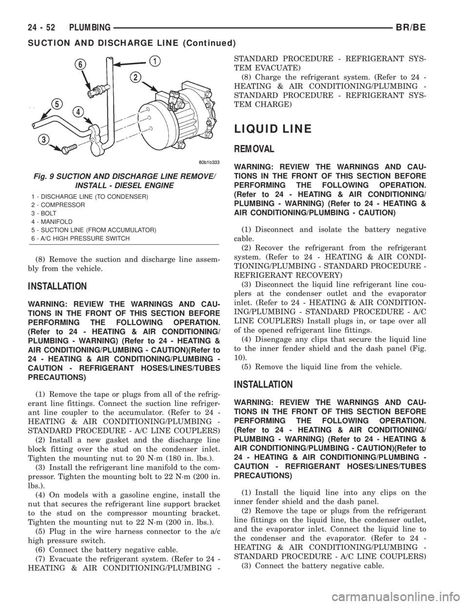
(8) Remove the suction and discharge line assem-
bly from the vehicle.
INSTALLATION
WARNING: REVIEW THE WARNINGS AND CAU-
TIONS IN THE FRONT OF THIS SECTION BEFORE
PERFORMING THE FOLLOWING OPERATION.
(Refer to 24 - HEATING & AIR CONDITIONING/
PLUMBING - WARNING) (Refer to 24 - HEATING &
AIR CONDITIONING/PLUMBING - CAUTION)(Refer to
24 - HEATING & AIR CONDITIONING/PLUMBING -
CAUTION - REFRIGERANT HOSES/LINES/TUBES
PRECAUTIONS)
(1) Remove the tape or plugs from all of the refrig-
erant line fittings. Connect the suction line refriger-
ant line coupler to the accumulator. (Refer to 24 -
HEATING & AIR CONDITIONING/PLUMBING -
STANDARD PROCEDURE - A/C LINE COUPLERS)
(2) Install a new gasket and the discharge line
block fitting over the stud on the condenser inlet.
Tighten the mounting nut to 20 N´m (180 in. lbs.).
(3) Install the refrigerant line manifold to the com-
pressor. Tighten the mounting bolt to 22 N´m (200 in.
lbs.).
(4) On models with a gasoline engine, install the
nut that secures the refrigerant line support bracket
to the stud on the compressor mounting bracket.
Tighten the mounting nut to 22 N´m (200 in. lbs.).
(5) Plug in the wire harness connector to the a/c
high pressure switch.
(6) Connect the battery negative cable.
(7) Evacuate the refrigerant system. (Refer to 24 -
HEATING & AIR CONDITIONING/PLUMBING -STANDARD PROCEDURE - REFRIGERANT SYS-
TEM EVACUATE)
(8) Charge the refrigerant system. (Refer to 24 -
HEATING & AIR CONDITIONING/PLUMBING -
STANDARD PROCEDURE - REFRIGERANT SYS-
TEM CHARGE)
LIQUID LINE
REMOVAL
WARNING: REVIEW THE WARNINGS AND CAU-
TIONS IN THE FRONT OF THIS SECTION BEFORE
PERFORMING THE FOLLOWING OPERATION.
(Refer to 24 - HEATING & AIR CONDITIONING/
PLUMBING - WARNING) (Refer to 24 - HEATING &
AIR CONDITIONING/PLUMBING - CAUTION)
(1) Disconnect and isolate the battery negative
cable.
(2) Recover the refrigerant from the refrigerant
system. (Refer to 24 - HEATING & AIR CONDI-
TIONING/PLUMBING - STANDARD PROCEDURE -
REFRIGERANT RECOVERY)
(3) Disconnect the liquid line refrigerant line cou-
plers at the condenser outlet and the evaporator
inlet. (Refer to 24 - HEATING & AIR CONDITION-
ING/PLUMBING - STANDARD PROCEDURE - A/C
LINE COUPLERS) Install plugs in, or tape over all
of the opened refrigerant line fittings.
(4) Disengage any clips that secure the liquid line
to the inner fender shield and the dash panel (Fig.
10).
(5) Remove the liquid line from the vehicle.
INSTALLATION
WARNING: REVIEW THE WARNINGS AND CAU-
TIONS IN THE FRONT OF THIS SECTION BEFORE
PERFORMING THE FOLLOWING OPERATION.
(Refer to 24 - HEATING & AIR CONDITIONING/
PLUMBING - WARNING) (Refer to 24 - HEATING &
AIR CONDITIONING/PLUMBING - CAUTION)(Refer to
24 - HEATING & AIR CONDITIONING/PLUMBING -
CAUTION - REFRIGERANT HOSES/LINES/TUBES
PRECAUTIONS)
(1) Install the liquid line into any clips on the
inner fender shield and the dash panel.
(2) Remove the tape or plugs from the refrigerant
line fittings on the liquid line, the condenser outlet,
and the evaporator inlet. Connect the liquid line to
the condenser and the evaporator. (Refer to 24 -
HEATING & AIR CONDITIONING/PLUMBING -
STANDARD PROCEDURE - A/C LINE COUPLERS)
(3) Connect the battery negative cable.
Fig. 9 SUCTION AND DISCHARGE LINE REMOVE/
INSTALL - DIESEL ENGINE
1 - DISCHARGE LINE (TO CONDENSER)
2 - COMPRESSOR
3 - BOLT
4 - MANIFOLD
5 - SUCTION LINE (FROM ACCUMULATOR)
6 - A/C HIGH PRESSURE SWITCH
24 - 52 PLUMBINGBR/BE
SUCTION AND DISCHARGE LINE (Continued)
Page 2175 of 2255
(2) Reassemble and reinstall the HVAC housing in
the vehicle. (Refer to 24 - HEATING & AIR CONDI-
TIONING/DISTRIBUTION/HVAC HOUSING -
ASSEMBLY) (Refer to 24 - HEATING & AIR CON-
DITIONING/DISTRIBUTION/HVAC HOUSING -
INSTALLATION)
NOTE: If the evaporator is replaced, add 60 millili-
ters (2 fluid ounces) of refrigerant oil to the refrig-
erant system.
A/C ORIFICE TUBE
DESCRIPTION
The fixed orifice tube is installed in the liquid line
between the outlet of the condenser and the inlet of
the evaporator. The fixed orifice tube is only serviced
as an integral part of the liquid line.
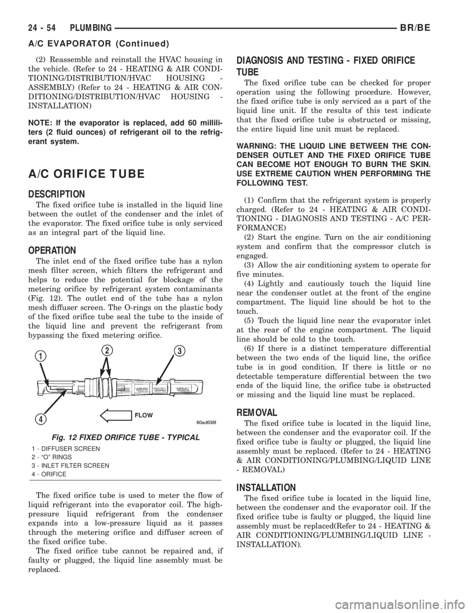
OPERATION
The inlet end of the fixed orifice tube has a nylon
mesh filter screen, which filters the refrigerant and
helps to reduce the potential for blockage of the
metering orifice by refrigerant system contaminants
(Fig. 12). The outlet end of the tube has a nylon
mesh diffuser screen. The O-rings on the plastic body
of the fixed orifice tube seal the tube to the inside of
the liquid line and prevent the refrigerant from
bypassing the fixed metering orifice.
The fixed orifice tube is used to meter the flow of
liquid refrigerant into the evaporator coil. The high-
pressure liquid refrigerant from the condenser
expands into a low-pressure liquid as it passes
through the metering orifice and diffuser screen of
the fixed orifice tube.
The fixed orifice tube cannot be repaired and, if
faulty or plugged, the liquid line assembly must be
replaced.
DIAGNOSIS AND TESTING - FIXED ORIFICE
TUBE
The fixed orifice tube can be checked for proper
operation using the following procedure. However,
the fixed orifice tube is only serviced as a part of the
liquid line unit. If the results of this test indicate
that the fixed orifice tube is obstructed or missing,
the entire liquid line unit must be replaced.
WARNING: THE LIQUID LINE BETWEEN THE CON-
DENSER OUTLET AND THE FIXED ORIFICE TUBE
CAN BECOME HOT ENOUGH TO BURN THE SKIN.
USE EXTREME CAUTION WHEN PERFORMING THE
FOLLOWING TEST.
(1) Confirm that the refrigerant system is properly
charged. (Refer to 24 - HEATING & AIR CONDI-
TIONING - DIAGNOSIS AND TESTING - A/C PER-
FORMANCE)
(2) Start the engine. Turn on the air conditioning
system and confirm that the compressor clutch is
engaged.
(3) Allow the air conditioning system to operate for
five minutes.
(4) Lightly and cautiously touch the liquid line
near the condenser outlet at the front of the engine
compartment. The liquid line should be hot to the
touch.
(5) Touch the liquid line near the evaporator inlet
at the rear of the engine compartment. The liquid
line should be cold to the touch.
(6) If there is a distinct temperature differential
between the two ends of the liquid line, the orifice
tube is in good condition. If there is little or no
detectable temperature differential between the two
ends of the liquid line, the orifice tube is obstructed
or missing and the liquid line must be replaced.
REMOVAL
The fixed orifice tube is located in the liquid line,
between the condenser and the evaporator coil. If the
fixed orifice tube is faulty or plugged, the liquid line
assembly must be replaced. (Refer to 24 - HEATING
& AIR CONDITIONING/PLUMBING/LIQUID LINE
- REMOVAL)
INSTALLATION
The fixed orifice tube is located in the liquid line,
between the condenser and the evaporator coil. If the
fixed orifice tube is faulty or plugged, the liquid line
assembly must be replaced(Refer to 24 - HEATING &
AIR CONDITIONING/PLUMBING/LIQUID LINE -
INSTALLATION).
Fig. 12 FIXED ORIFICE TUBE - TYPICAL
1 - DIFFUSER SCREEN
2 - ªOº RINGS
3 - INLET FILTER SCREEN
4 - ORIFICE
24 - 54 PLUMBINGBR/BE
A/C EVAPORATOR (Continued)
Page 2180 of 2255
EMISSIONS CONTROL
TABLE OF CONTENTS
page page
EMISSIONS CONTROL
DESCRIPTION
DESCRIPTION - DIESEL.................1
DESCRIPTION - STATE DISPLAY TEST
MODE...............................1
DESCRIPTION - CIRCUIT ACTUATION TEST
MODE...............................2
DESCRIPTION - DIAGNOSTIC TROUBLE
CODES..............................2
DESCRIPTION - TASK MANAGER.........17
DESCRIPTION - MONITORED SYSTEMS . . . 17
DESCRIPTION - TRIP DEFINITION........19
DESCRIPTION - COMPONENT MONITORS -
GAS ENGINES.......................19DESCRIPTION - COMPONENT MONITORS -
DIESEL ENGINES.....................20
OPERATION
OPERATION - GAS ENGINES............20
OPERATION - DIESEL..................20
OPERATION - TASK MANAGER..........21
OPERATION - NON-MONITORED
CIRCUITS - GAS ENGINES..............24
OPERATION - NON-MONITORED
CIRCUITS - DIESEL....................24
AIR INJECTION.........................26
EVAPORATIVE EMISSIONS................32
EMISSIONS CONTROL
DESCRIPTION
DESCRIPTION - DIESEL
Two different modules are used for powertrain con-
trol with the diesel engine. The Powertrain Control
Module (PCM) is used primarily for charging system,
transmission, A/C compressor clutch operation and
speed control functions. The Engine Control Module
(ECM) is used to control thefuel and emissions
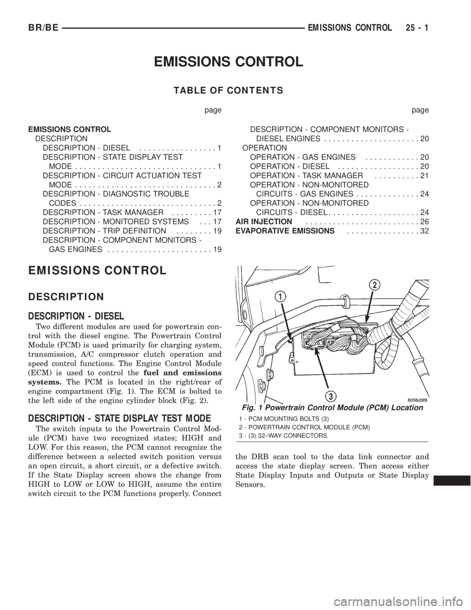
systems.The PCM is located in the right/rear of
engine compartment (Fig. 1). The ECM is bolted to
the left side of the engine cylinder block (Fig. 2).
DESCRIPTION - STATE DISPLAY TEST MODE
The switch inputs to the Powertrain Control Mod-
ule (PCM) have two recognized states; HIGH and
LOW. For this reason, the PCM cannot recognize the
difference between a selected switch position versus
an open circuit, a short circuit, or a defective switch.
If the State Display screen shows the change from
HIGH to LOW or LOW to HIGH, assume the entire
switch circuit to the PCM functions properly. Connectthe DRB scan tool to the data link connector and
access the state display screen. Then access either
State Display Inputs and Outputs or State Display
Sensors.
Fig. 1 Powertrain Control Module (PCM) Location
1 - PCM MOUNTING BOLTS (3)
2 - POWERTRAIN CONTROL MODULE (PCM)
3 - (3) 32±WAY CONNECTORS
BR/BEEMISSIONS CONTROL 25 - 1
Page 2189 of 2255
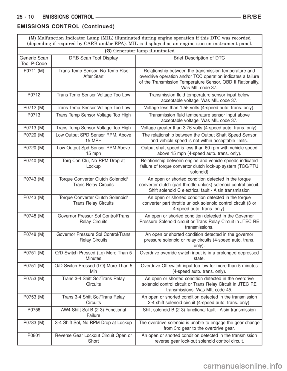
(M)Malfunction Indicator Lamp (MIL) illuminated during engine operation if this DTC was recorded
(depending if required by CARB and/or EPA). MIL is displayed as an engine icon on instrument panel.
(G)Generator lamp illuminated
Generic Scan
Tool P-CodeDRB Scan Tool Display Brief Description of DTC
P0711 (M) Trans Temp Sensor, No Temp Rise
After StartRelationship between the transmission temperature and
overdrive operation and/or TCC operation indicates a failure
of the Transmission Temperature Sensor. OBD II Rationality.
Was MIL code 37.
P0712 Trans Temp Sensor Voltage Too Low Transmission fluid temperature sensor input below
acceptable voltage. Was MIL code 37.
P0712 (M) Trans Temp Sensor Voltage Too Low Voltage less than 1.55 volts (4-speed auto. trans. only).
P0713 Trans Temp Sensor Voltage Too High Transmission fluid temperature sensor input above
acceptable voltage. Was MIL code 37.
P0713 (M) Trans Temp Sensor Voltage Too High Voltage greater than 3.76 volts (4-speed auto. trans. only).
P0720 (M) Low Output SPD Sensor RPM, Above
15 MPHThe relationship between the Output Shaft Speed Sensor
and vehicle speed is not within acceptable limits.
P0720 (M) Low Output Spd Sensor RPM Above
15 mphOutput shaft speed is less than 60 rpm with vehicle speed
above 15 mph (4-speed auto. trans. only).
P0740 (M) Torq Con Clu, No RPM Drop at
LockupRelationship between engine and vehicle speeds indicated
failure of torque convertor clutch lock-up system (TCC/PTU
solenoid)
P0743 (M) Torque Converter Clutch Solenoid/
Trans Relay CircuitsAn open or shorted condition detected in the torque
converter clutch (part throttle unlock) solenoid control circuit.
Shift solenoid C electrical fault - Aisin transmission
P0743 (M) Torque Converter Clutch Solenoid/
Trans Relay CircuitsAn open or shorted condition detected in the torque
converter part throttle unlock solenoid control circuit (3 or
4-speed auto. trans. only).
P0748 (M) Governor Pressur Sol Control/Trans
Relay CircuitsAn open or shorted condition detected in the Governor
Pressure Solenoid circuit or Trans Relay Circuit in JTEC RE
transmissions.
P0748 (M) Governor Pressure Sol Control/Trans
Relay CircuitsAn open or shorted condition detected in the governor
pressure solenoid or relay circuits (4-speed auto. trans.
only).
P0751 (M) O/D Switch Pressed (Lo) More Than 5
MinutesOverdrive override switch input is in a prolonged depressed
state.
P0751 (M) O/D Switch Pressed (LO) More Than 5
MinOverdrive Off switch input too low for more than 5 minutes
(4-speed auto. trans. only).
P0753 (M) Trans 3-4 Shift Sol/Trans Relay
CircuitsAn open or shorted condition detected in the overdrive
solenoid control circuit or Trans Relay Circuit in JTEC RE
transmissions. Was MIL code 45.
P0753 (M) Trans 3-4 Shift Sol/Trans Relay
CircuitsAn open or shorted condition detected in the transmission
2-4 shift solenoid circuit (4-speed auto. trans. only).
P0756 AW4 Shift Sol B (2-3) Functional
FailureShift solenoid B (2-3) functional fault - Aisin transmission
P0783 (M) 3-4 Shift Sol, No RPM Drop at Lockup The overdrive solenoid is unable to engage the gear change
from 3rd gear to the overdrive gear.
P0801 Reverse Gear Lockout Circuit Open or
ShortAn open or shorted condition detected in the transmission
reverse gear lock-out solenoid control circuit.
25 - 10 EMISSIONS CONTROLBR/BE
EMISSIONS CONTROL (Continued)