2002 DODGE RAM automatic transmission fluid
[x] Cancel search: automatic transmission fluidPage 1623 of 2255
OIL PUMP BODY
(1) Lubricate pump gears with transmission fluid
and install them in pump body.(2) Install thrust washer on reaction shaft support
hub. Lubricate washer with petroleum jelly or trans-
mission fluid before installation.
(3) If reaction shaft seal rings are being replaced,
install new seal rings on support hub. Lubricate seal
rings with transmission fluid or petroleum jelly after
installation. Squeeze each ring until ring ends are
securely hooked together.
CAUTION: The reaction shaft support seal rings will
break if overspread, or twisted. If new rings are
being installed, spread them only enough for instal-
lation. Also be very sure the ring ends are securely
hooked together after installation. Otherwise, the
rings will either prevent pump installation, or break
during installation.
(4) Align and install reaction shaft support on
pump body.
(5) Install bolts attaching reaction shaft support to
pump. Tighten bolts to 20 N´m (175 in. lbs.) torque.
(6) Install new pump seal with Installer Tool
C-3860-A (Fig. 115). Use hammer or mallet to tap
seal into place.
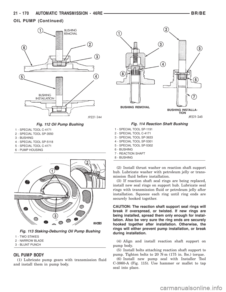
Fig. 112 Oil Pump Bushing
1 - SPECIAL TOOL C-4171
2 - SPECIAL TOOL SP-3550
3 - BUSHING
4 - SPECIAL TOOL SP-5118
5 - SPECIAL TOOL C-4171
6 - PUMP HOUSING
Fig. 113 Staking-Deburring Oil Pump Bushing
1 - TWO STAKES
2 - NARROW BLADE
3 - BLUNT PUNCH
Fig. 114 Reaction Shaft Bushing
1 - SPECIAL TOOL SP-1191
2 - SPECIAL TOOL C-4171
3 - SPECIAL TOOL SP-3633
4 - SPECIAL TOOL SP-5301
5 - SPECIAL TOOL SP-5302
6 - BUSHING
7 - REACTION SHAFT
8 - BUSHING
21 - 170 AUTOMATIC TRANSMISSION - 46REBR/BE
OIL PUMP (Continued)
Page 1625 of 2255
INSTALLATION
(1) Place replacement bearing in position in hous-
ing.
(2) Using a suitable driver, drive bearing into
housing until the snap-ring groove is visible.
(3) Install snap-ring to hold bearing into housing
(Fig. 117).
(4) Install overdrive geartrain into housing.
(5) Install overdrive unit in vehicle.
OVERDRIVE CLUTCH
DESCRIPTION
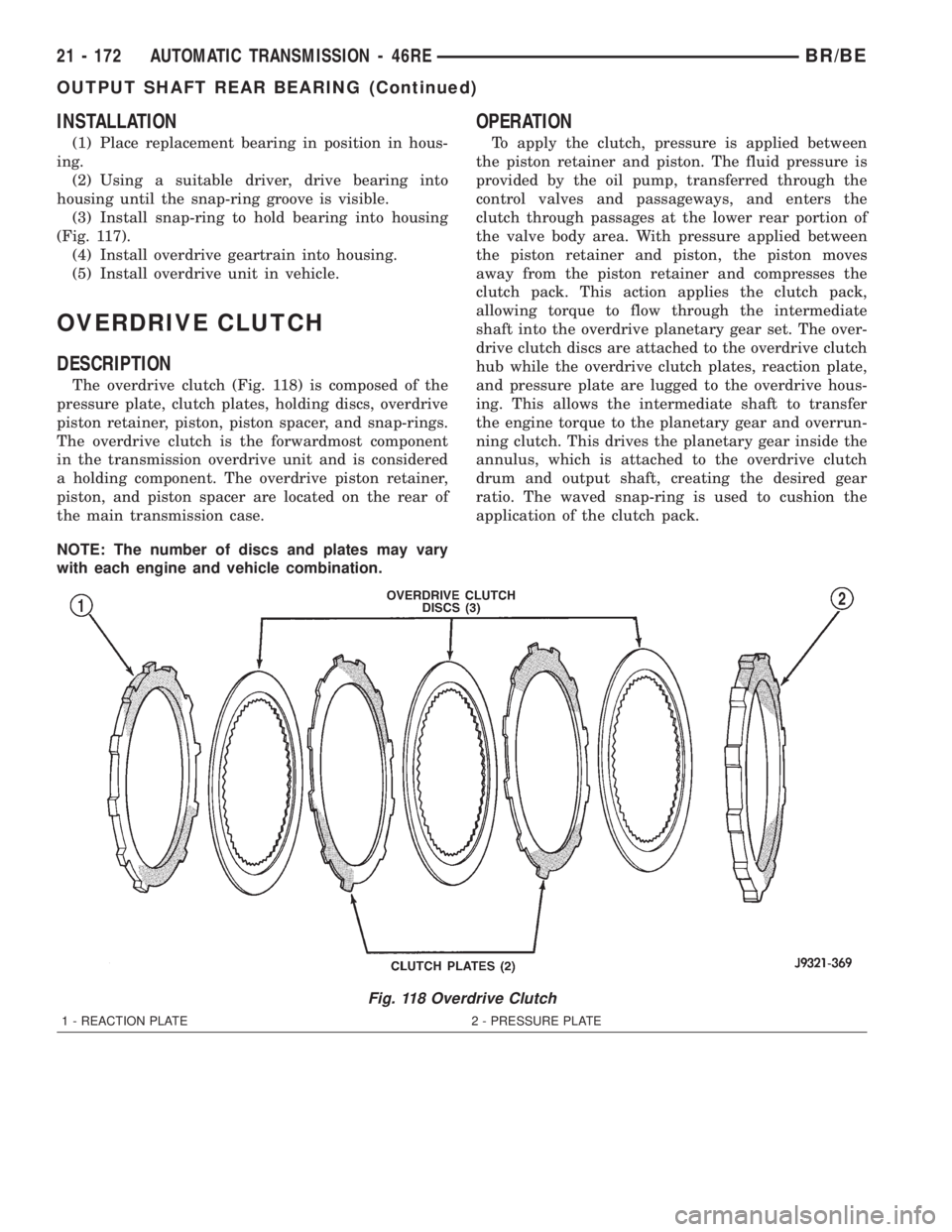
The overdrive clutch (Fig. 118) is composed of the
pressure plate, clutch plates, holding discs, overdrive
piston retainer, piston, piston spacer, and snap-rings.
The overdrive clutch is the forwardmost component
in the transmission overdrive unit and is considered
a holding component. The overdrive piston retainer,
piston, and piston spacer are located on the rear of
the main transmission case.
NOTE: The number of discs and plates may vary
with each engine and vehicle combination.
OPERATION
To apply the clutch, pressure is applied between
the piston retainer and piston. The fluid pressure is
provided by the oil pump, transferred through the
control valves and passageways, and enters the
clutch through passages at the lower rear portion of
the valve body area. With pressure applied between
the piston retainer and piston, the piston moves
away from the piston retainer and compresses the
clutch pack. This action applies the clutch pack,
allowing torque to flow through the intermediate
shaft into the overdrive planetary gear set. The over-
drive clutch discs are attached to the overdrive clutch
hub while the overdrive clutch plates, reaction plate,
and pressure plate are lugged to the overdrive hous-
ing. This allows the intermediate shaft to transfer
the engine torque to the planetary gear and overrun-
ning clutch. This drives the planetary gear inside the
annulus, which is attached to the overdrive clutch
drum and output shaft, creating the desired gear
ratio. The waved snap-ring is used to cushion the
application of the clutch pack.
Fig. 118 Overdrive Clutch
1 - REACTION PLATE 2 - PRESSURE PLATE
21 - 172 AUTOMATIC TRANSMISSION - 46REBR/BE
OUTPUT SHAFT REAR BEARING (Continued)
Page 1626 of 2255
OVERDRIVE UNIT
REMOVAL
(1) Shift transmission into PARK.
(2) Raise vehicle.
(3) Remove transfer case, if equipped.
(4) Mark propeller shaft universal joint(s) and axle
pinion yoke, or the companion flange and flange
yoke, for alignment reference at installation, if necc-
esary.
(5) Disconnect and remove the rear propeller shaft,
if necessary. (Refer to 3 - DIFFERENTIAL & DRIV-
ELINE/PROPELLER SHAFT/PROPELLER SHAFT -
REMOVAL)
(6) Remove transmission oil pan, remove gasket,
drain oil and reinstall pan.
(7) If overdrive unit had malfunctioned, or if fluid
is contaminated, remove entire transmission. If diag-
nosis indicated overdrive problems only, remove just
the overdrive unit.
(8) Support transmission with transmission jack.
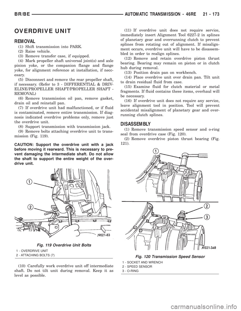
(9) Remove bolts attaching overdrive unit to trans-
mission (Fig. 119).
CAUTION: Support the overdrive unit with a jack
before moving it rearward. This is necessary to pre-
vent damaging the intermediate shaft. Do not allow
the shaft to support the entire weight of the over-
drive unit.
(10) Carefully work overdrive unit off intermediate
shaft. Do not tilt unit during removal. Keep it as
level as possible.(11) If overdrive unit does not require service,
immediately insert Alignment Tool 6227-2 in splines
of planetary gear and overrunning clutch to prevent
splines from rotating out of alignment. If misalign-
ment occurs, overdrive unit will have to be disassem-
bled in order to realign splines.
(12) Remove and retain overdrive piston thrust
bearing. Bearing may remain on piston or in clutch
hub during removal.
(13) Position drain pan on workbench.
(14) Place overdrive unit over drain pan. Tilt unit
to drain residual fluid from case.
(15) Examine fluid for clutch material or metal
fragments. If fluid contains these items, overhaul will
be necessary.
(16) If overdrive unit does not require any service,
leave alignment tool in position. Tool will prevent
accidental misalignment of planetary gear and over-
running clutch splines.
DISASSEMBLY
(1) Remove transmission speed sensor and o-ring
seal from overdrive case (Fig. 120).
(2) Remove overdrive piston thrust bearing (Fig.
121).
Fig. 119 Overdrive Unit Bolts
1 - OVERDRIVE UNIT
2 - ATTACHING BOLTS (7)
Fig. 120 Transmission Speed Sensor
1 - SOCKET AND WRENCH
2 - SPEED SENSOR
3 - O-RING
BR/BEAUTOMATIC TRANSMISSION - 46RE 21 - 173
Page 1633 of 2255
Do not use shop towels for wiping parts dry unless
the towels are made from a lint-free material. A suf-
ficient quantity of lint (from shop towels, cloths, rags,
etc.) could plug the transmission filter and fluid pas-
sages.
Discard the old case gasket and seals. Do not
attempt to salvage these parts. They are not reus-
able. Replace any of the overdrive unit snap-rings if
distorted or damaged.
Minor nicks or scratches on components can be
smoothed with crocus cloth. However, do not attempt
to reduce severe scoring on any components with
abrasive materials. Replace severely scored compo-
nents; do not try to salvage them.
INSPECTION
Check condition of the park lock components and
the overdrive case.
Check the bushings in the overdrive case. Replace
the bushings if severely scored or worn. Also replace
the case seal if loose, distorted, or damaged.
Examine the overdrive and direct clutch discs and
plates. Replace the discs if the facing is worn,
severely scored, or burned and flaking off. Replace
the clutch plates if worn, heavily scored, or cracked.
Check the lugs on the clutch plates for wear. The
plates should slide freely in the drum. Replace the
plates or drum if binding occurs.
Check condition of the annulus gear, direct clutch
hub, clutch drum and clutch spring. Replace the gear,
hub and drum if worn or damaged. Replace the
spring if collapsed, distorted, or cracked.
Be sure the splines and lugs on the gear, drum and
hub are in good condition. The clutch plates and
discs should slide freely in these components.
Inspect the thrust bearings and spring plate.
Replace the plate if worn or scored. Replace the bear-
ings if rough, noisy, brinnelled, or worn.
Inspect the planetary gear assembly and the sun
gear and bushings. If either the sun gear or the
bushings are damaged, replace the gear and bush-
ings as an assembly. The gear and bushings are not
serviced separately.
The planetary carrier and pinions must be in good
condition. Also be sure the pinion pins are secure and in
good condition. Replace the carrier if worn or damaged.
Inspect the overrunning clutch and race. The race
surface should be smooth and free of scores. Replace
the overrunning clutch assembly or the race if either
assembly is worn or damaged in any way.
Replace the shaft pilot bushing and inner bushing
if damaged. Replace either shaft bearing if rough or
noisy. Replace the bearing snap-rings if distorted or
cracked.
Check the machined surfaces on the output shaft.
These surfaces should clean and smooth. Very minor
nicks or scratches can be smoothed with crocus cloth.
Replace the shaft if worn, scored or damaged in any
way.
Inspect the output shaft bushings. The small bush-
ing is the intermediate shaft pilot bushing. The large
bushing is the overrunning clutch hub bushing.
Replace either bushing if scored, pitted, cracked, or
worn.
ASSEMBLY
GEARTRAIN AND DIRECT CLUTCH
(1) Soak direct clutch and overdrive clutch discs in
MopartATF +4, type 9602, transmission fluid. Allow
discs to soak for 10-20 minutes.
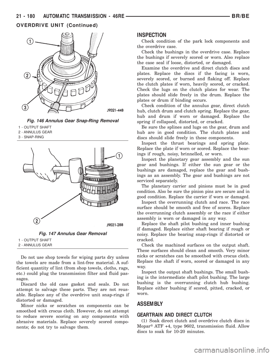
Fig. 146 Annulus Gear Snap-Ring Removal
1 - OUTPUT SHAFT
2 - ANNULUS GEAR
3 - SNAP-RING
Fig. 147 Annulus Gear Removal
1 - OUTPUT SHAFT
2 - ANNULUS GEAR
21 - 180 AUTOMATIC TRANSMISSION - 46REBR/BE
OVERDRIVE UNIT (Continued)
Page 1634 of 2255
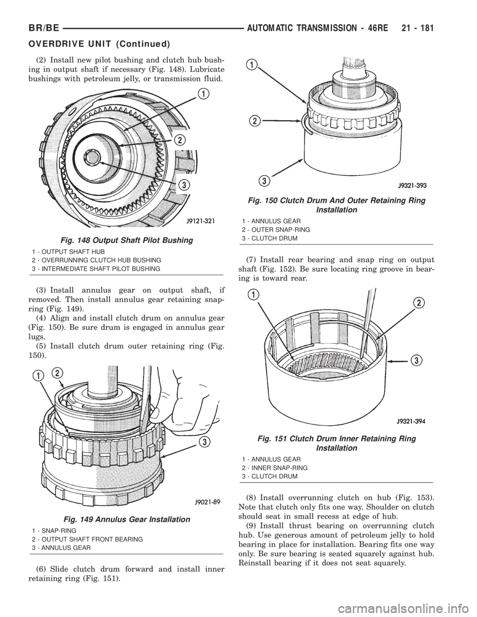
(2) Install new pilot bushing and clutch hub bush-
ing in output shaft if necessary (Fig. 148). Lubricate
bushings with petroleum jelly, or transmission fluid.
(3) Install annulus gear on output shaft, if
removed. Then install annulus gear retaining snap-
ring (Fig. 149).
(4) Align and install clutch drum on annulus gear
(Fig. 150). Be sure drum is engaged in annulus gear
lugs.
(5) Install clutch drum outer retaining ring (Fig.
150).
(6) Slide clutch drum forward and install inner
retaining ring (Fig. 151).(7) Install rear bearing and snap ring on output
shaft (Fig. 152). Be sure locating ring groove in bear-
ing is toward rear.
(8) Install overrunning clutch on hub (Fig. 153).
Note that clutch only fits one way. Shoulder on clutch
should seat in small recess at edge of hub.
(9) Install thrust bearing on overrunning clutch
hub. Use generous amount of petroleum jelly to hold
bearing in place for installation. Bearing fits one way
only. Be sure bearing is seated squarely against hub.
Reinstall bearing if it does not seat squarely.
Fig. 148 Output Shaft Pilot Bushing
1 - OUTPUT SHAFT HUB
2 - OVERRUNNING CLUTCH HUB BUSHING
3 - INTERMEDIATE SHAFT PILOT BUSHING
Fig. 149 Annulus Gear Installation
1 - SNAP-RING
2 - OUTPUT SHAFT FRONT BEARING
3 - ANNULUS GEAR
Fig. 150 Clutch Drum And Outer Retaining Ring
Installation
1 - ANNULUS GEAR
2 - OUTER SNAP-RING
3 - CLUTCH DRUM
Fig. 151 Clutch Drum Inner Retaining Ring
Installation
1 - ANNULUS GEAR
2 - INNER SNAP-RING
3 - CLUTCH DRUM
BR/BEAUTOMATIC TRANSMISSION - 46RE 21 - 181
OVERDRIVE UNIT (Continued)
Page 1648 of 2255

(c) Install piston over Seal Guide 8114-3 and
inside Guide Ring 8114-1.
(d) Push overdrive piston into position in
retainer.
(e) Verify that the locating lugs entered the lug
bores in the retainer.
PARK/NEUTRAL POSITION
SWITCH
DIAGNOSIS AND TESTING - PARK/NEUTRAL
POSITION SWITCH
The center terminal of the park/neutral position
switch is the starter-circuit terminal. It provides the
ground for the starter solenoid circuit through the
selector lever in PARK and NEUTRAL positions only.
The outer terminals on the switch are for the backup
lamp circuit.
SWITCH TEST
To test the switch, remove the wiring connector.
Test for continuity between the center terminal and
the transmission case. Continuity should exist only
when the transmission is in PARK or NEUTRAL.
Shift the transmission into REVERSE and test
continuity at the switch outer terminals. Continuity
should exist only when the transmission is in
REVERSE. Continuity should not exist between the
outer terminals and the case.Check gearshift linkage adjustment before replac-
ing a switch that tests faulty.
REMOVAL
(1) Raise vehicle and position drain pan under
switch.
(2) Disconnect switch wires.
(3) Remove switch from case.
INSTALLATION
(1) Move shift lever to PARK and NEUTRAL posi-
tions. Verify that switch operating lever fingers are
centered in switch opening in case (Fig. 196).
(2) Install new seal on switch and install switch in
case. Tighten switch to 34 N´m (25 ft. lbs.) torque.
(3) Test continuity of new switch with 12V test
lamp.
(4) Connect switch wires and lower vehicle.
(5) Top off transmission fluid level.
PISTONS
DESCRIPTION
There are several sizes and types of pistons used in
an automatic transmission. Some pistons are used to
apply clutches, while others are used to apply bands.
They all have in common the fact that they are
round or circular in shape, located within a smooth
walled cylinder, which is closed at one end and con-
verts fluid pressure into mechanical movement. The
fluid pressure exerted on the piston is contained
within the system through the use of piston rings or
seals.
Fig. 195 Aligning Overdrive Piston Retainer
1 - PISTON RETAINER
2 - GASKET
3 - RETAINER BOLTS
Fig. 196 Park/Neutral Position Switch
1 - NEUTRAL CONTACT
2 - MANUAL LEVER AND SWITCH PLUNGER IN REVERSE
POSITION
3 - PARK CONTACT
4 - SWITCH
BR/BEAUTOMATIC TRANSMISSION - 46RE 21 - 195
OVERRUNNING CLUTCH CAM/OVERDRIVE PISTON RETAINER (Continued)
Page 1649 of 2255
OPERATION
The principal which makes this operation possible
is known as Pascal's Law. Pascal's Law can be stated
as: ªPressure on a confined fluid is transmitted
equally in all directions and acts with equal force on
equal areas.º
PRESSURE
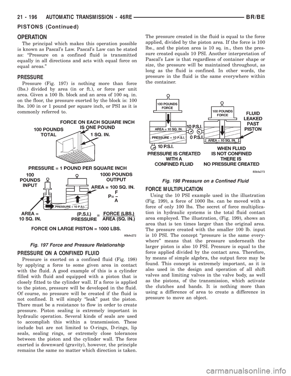
Pressure (Fig. 197) is nothing more than force
(lbs.) divided by area (in or ft.), or force per unit
area. Given a 100 lb. block and an area of 100 sq. in.
on the floor, the pressure exerted by the block is: 100
lbs. 100 in or 1 pound per square inch, or PSI as it is
commonly referred to.
PRESSURE ON A CONFINED FLUID
Pressure is exerted on a confined fluid (Fig. 198)
by applying a force to some given area in contact
with the fluid. A good example of this is a cylinder
filled with fluid and equipped with a piston that is
closely fitted to the cylinder wall. If a force is applied
to the piston, pressure will be developed in the fluid.
Of course, no pressure will be created if the fluid is
not confined. It will simply ªleakº past the piston.
There must be a resistance to flow in order to create
pressure. Piston sealing is extremely important in
hydraulic operation. Several kinds of seals are used
to accomplish this within a transmission. These
include but are not limited to O-rings, D-rings, lip
seals, sealing rings, or extremely close tolerances
between the piston and the cylinder wall. The force
exerted is downward (gravity), however, the principle
remains the same no matter which direction is taken.The pressure created in the fluid is equal to the force
applied, divided by the piston area. If the force is 100
lbs., and the piston area is 10 sq. in., then the pres-
sure created equals 10 PSI. Another interpretation of
Pascal's Law is that regardless of container shape or
size, the pressure will be maintained throughout, as
long as the fluid is confined. In other words, the
pressure in the fluid is the same everywhere within
the container.
FORCE MULTIPLICATION
Using the 10 PSI example used in the illustration
(Fig. 199), a force of 1000 lbs. can be moved with a
force of only 100 lbs. The secret of force multiplica-
tion in hydraulic systems is the total fluid contact
area employed. The illustration, (Fig. 199), shows an
area that is ten times larger than the original area.
The pressure created with the smaller 100 lb. input
is 10 PSI. The concept ªpressure is the same every-
whereº means that the pressure underneath the
larger piston is also 10 PSI. Pressure is equal to the
force applied divided by the contact area. Therefore,
by means of simple algebra, the output force may be
found. This concept is extremely important, as it is
also used in the design and operation of all shift
valves and limiting valves in the valve body, as well
as the pistons, of the transmission, which activate
the clutches and bands. It is nothing more than
using a difference of area to create a difference in
pressure to move an object.
Fig. 197 Force and Pressure Relationship
Fig. 198 Pressure on a Confined Fluid
21 - 196 AUTOMATIC TRANSMISSION - 46REBR/BE
PISTONS (Continued)
Page 1652 of 2255

INSPECTION
Inspect the planetary gear sets and annulus gears.
The planetary pinions, shafts, washers, and retaining
pins are serviceable. However, if a pinion carrier is
damaged, the entire planetary gear set must be
replaced as an assembly.
Replace the annulus gears if the teeth are chipped,
broken, or worn, or the gear is cracked. Replace the
planetary thrust plates and the tabbed thrust wash-
ers if cracked, scored or worn.
Inspect the machined surfaces of the intermediate
shaft. Be sure the oil passages are open and clear.
Replace the shaft if scored, pitted, or damaged.
Inspect the sun gear and driving shell. If either
component is worn or damaged, remove the sun gear
rear retaining ring and separate the sun gear andthrust plate from the driving shell. Then replace the
necessary component.
Replace the sun gear as an assembly if the gear
teeth are chipped or worn. Also replace the gear as
an assembly if the bushings are scored or worn. The
sun gear bushings are not serviceable. Replace the
thrust plate if worn, or severely scored. Replace the
driving shell if distorted, cracked, or damaged in any
way.
Replace all snap-rings during geartrain assembly.
Reusing snap-rings is not recommended.
ASSEMBLY
(1) Lubricate sun gear and planetary gears with
transmission fluid during assembly. Use petroleum
jelly to lubricate intermediate shaft bushing surfaces,
thrust washers and thrust plates and to hold these
parts in place during assembly.
Fig. 206 Sun Gear And Driving Shell Removal
1 - INTERMEDIATE SHAFT
2 - DRIVING SHELL
3 - SUN GEAR
Fig. 207 Rear Planetary Thrust Washer Removal
1 - SUN GEAR
2 - REAR PLANETARY THRUST WASHER
3 - DRIVING SHELL
Fig. 208 Rear Planetary And Annulus Gear Removal
1 - INTERMEDIATE SHAFT
2 - REAR ANNULUS GEAR
3 - REAR PLANETARY GEAR
Fig. 209 Rear Annulus Thrust Plate Removal
1 - REAR ANNULUS GEAR
2 - THRUST PLATE
BR/BEAUTOMATIC TRANSMISSION - 46RE 21 - 199
PLANETARY GEARTRAIN/OUTPUT SHAFT (Continued)