2002 DODGE RAM automatic transmission fluid
[x] Cancel search: automatic transmission fluidPage 1562 of 2255

CONDITION POSSIBLE CAUSES CORRECTION
NO 4-3 DOWNSHIFT
WHEN CONTROL SWITCH
IS TURNED OFF1. Control Switch Open/Shorted. 1. Test and replace switch if faulty.
2. Overdrive Solenoid Connector
Shorted.2. Test solenoids and replace if seized or
shorted.
3. PCM Malfunction. 3. Test with DRBTscan tool. Replace PCM
if faulty.
4. Valve Body Stuck Valves. 4. Repair stuck 3-4, lockup or lockup timing
valve.
CLUNK NOISE FROM
DRIVELINE ON CLOSED
THROTTLE 4-3
DOWNSHIFT1. Transmission Fluid Low. 1. Add Fluid.
2. Throttle Cable Mis-adjusted. 2. Adjust cable.
3. Overdrive Clutch Select Spacer
Wrong Spacer.3. Replace overdrive piston thrust plate
spacer.
3-4 UPSHIFT OCCURS
IMMEDIATELY AFTER 2-3
SHIFT1. Overdrive Solenoid Connector or
Wiring Shorted.1. Test connector and wiring for loose
connections, shorts or ground and repair as
needed.
2. TPS Malfunction. 2. Test TPS and replace as necessary.
Check with DRBTscan tool.
3. PCM Malfunction. 3. Test PCM with DRBTscan tool and
replace controller if faulty.
4. Overdrive Solenoid Malfunction. 4. Replace solenoid.
5. Valve Body Malfunction. 5. Remove, disassemble, clean and inspect
valve body components. Make sure all
valves and plugs slide freely in bores.
Polish valves with crocus cloth if needed.
WHINE/NOISE RELATED
TO ENGINE SPEED1. Fluid Level Low. 1. Add fluid and check for leaks.
2. Shift Cable Incorrect Routing. 2. Check shift cable for correct routing.
Should not touch engine or bell housing.
BR/BEAUTOMATIC TRANSMISSION - 46RE 21 - 109
AUTOMATIC TRANSMISSION - 46RE (Continued)
Page 1564 of 2255
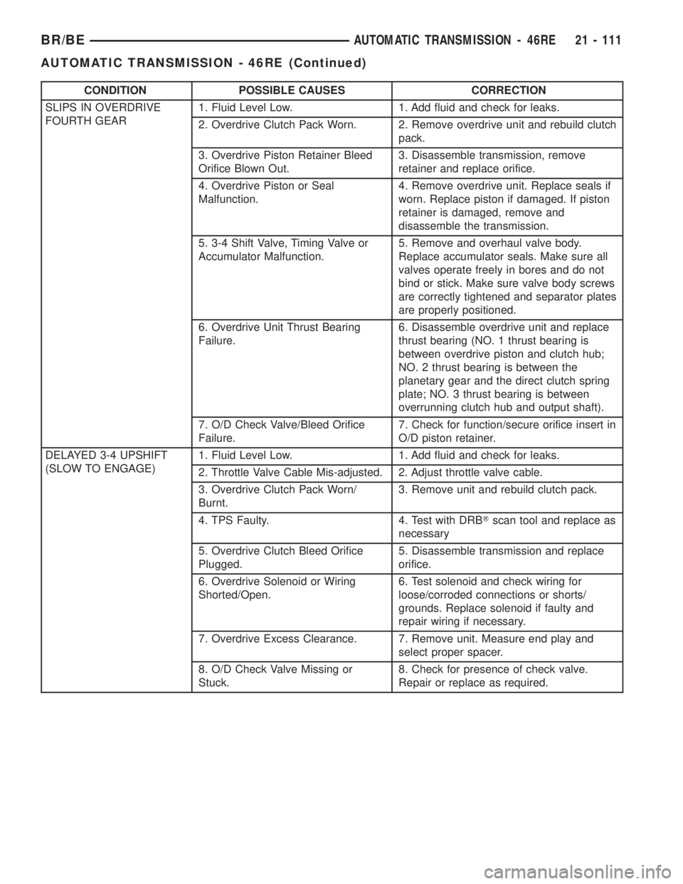
CONDITION POSSIBLE CAUSES CORRECTION
SLIPS IN OVERDRIVE
FOURTH GEAR1. Fluid Level Low. 1. Add fluid and check for leaks.
2. Overdrive Clutch Pack Worn. 2. Remove overdrive unit and rebuild clutch
pack.
3. Overdrive Piston Retainer Bleed
Orifice Blown Out.3. Disassemble transmission, remove
retainer and replace orifice.
4. Overdrive Piston or Seal
Malfunction.4. Remove overdrive unit. Replace seals if
worn. Replace piston if damaged. If piston
retainer is damaged, remove and
disassemble the transmission.
5. 3-4 Shift Valve, Timing Valve or
Accumulator Malfunction.5. Remove and overhaul valve body.
Replace accumulator seals. Make sure all
valves operate freely in bores and do not
bind or stick. Make sure valve body screws
are correctly tightened and separator plates
are properly positioned.
6. Overdrive Unit Thrust Bearing
Failure.6. Disassemble overdrive unit and replace
thrust bearing (NO. 1 thrust bearing is
between overdrive piston and clutch hub;
NO. 2 thrust bearing is between the
planetary gear and the direct clutch spring
plate; NO. 3 thrust bearing is between
overrunning clutch hub and output shaft).
7. O/D Check Valve/Bleed Orifice
Failure.7. Check for function/secure orifice insert in
O/D piston retainer.
DELAYED 3-4 UPSHIFT
(SLOW TO ENGAGE)1. Fluid Level Low. 1. Add fluid and check for leaks.
2. Throttle Valve Cable Mis-adjusted. 2. Adjust throttle valve cable.
3. Overdrive Clutch Pack Worn/
Burnt.3. Remove unit and rebuild clutch pack.
4. TPS Faulty. 4. Test with DRBTscan tool and replace as
necessary
5. Overdrive Clutch Bleed Orifice
Plugged.5. Disassemble transmission and replace
orifice.
6. Overdrive Solenoid or Wiring
Shorted/Open.6. Test solenoid and check wiring for
loose/corroded connections or shorts/
grounds. Replace solenoid if faulty and
repair wiring if necessary.
7. Overdrive Excess Clearance. 7. Remove unit. Measure end play and
select proper spacer.
8. O/D Check Valve Missing or
Stuck.8. Check for presence of check valve.
Repair or replace as required.
BR/BEAUTOMATIC TRANSMISSION - 46RE 21 - 111
AUTOMATIC TRANSMISSION - 46RE (Continued)
Page 1566 of 2255
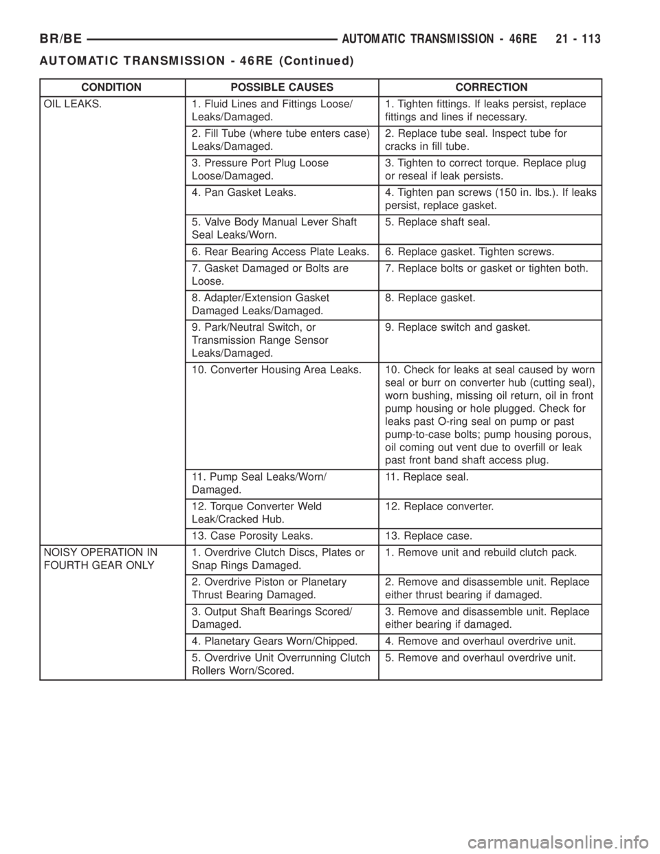
CONDITION POSSIBLE CAUSES CORRECTION
OIL LEAKS. 1. Fluid Lines and Fittings Loose/
Leaks/Damaged.1. Tighten fittings. If leaks persist, replace
fittings and lines if necessary.
2. Fill Tube (where tube enters case)
Leaks/Damaged.2. Replace tube seal. Inspect tube for
cracks in fill tube.
3. Pressure Port Plug Loose
Loose/Damaged.3. Tighten to correct torque. Replace plug
or reseal if leak persists.
4. Pan Gasket Leaks. 4. Tighten pan screws (150 in. lbs.). If leaks
persist, replace gasket.
5. Valve Body Manual Lever Shaft
Seal Leaks/Worn.5. Replace shaft seal.
6. Rear Bearing Access Plate Leaks. 6. Replace gasket. Tighten screws.
7. Gasket Damaged or Bolts are
Loose.7. Replace bolts or gasket or tighten both.
8. Adapter/Extension Gasket
Damaged Leaks/Damaged.8. Replace gasket.
9. Park/Neutral Switch, or
Transmission Range Sensor
Leaks/Damaged.9. Replace switch and gasket.
10. Converter Housing Area Leaks. 10. Check for leaks at seal caused by worn
seal or burr on converter hub (cutting seal),
worn bushing, missing oil return, oil in front
pump housing or hole plugged. Check for
leaks past O-ring seal on pump or past
pump-to-case bolts; pump housing porous,
oil coming out vent due to overfill or leak
past front band shaft access plug.
11. Pump Seal Leaks/Worn/
Damaged.11. Replace seal.
12. Torque Converter Weld
Leak/Cracked Hub.12. Replace converter.
13. Case Porosity Leaks. 13. Replace case.
NOISY OPERATION IN
FOURTH GEAR ONLY1. Overdrive Clutch Discs, Plates or
Snap Rings Damaged.1. Remove unit and rebuild clutch pack.
2. Overdrive Piston or Planetary
Thrust Bearing Damaged.2. Remove and disassemble unit. Replace
either thrust bearing if damaged.
3. Output Shaft Bearings Scored/
Damaged.3. Remove and disassemble unit. Replace
either bearing if damaged.
4. Planetary Gears Worn/Chipped. 4. Remove and overhaul overdrive unit.
5. Overdrive Unit Overrunning Clutch
Rollers Worn/Scored.5. Remove and overhaul overdrive unit.
BR/BEAUTOMATIC TRANSMISSION - 46RE 21 - 113
AUTOMATIC TRANSMISSION - 46RE (Continued)
Page 1567 of 2255
STANDARD PROCEDURE - ALUMINUM
THREAD REPAIR
Damaged or worn threads in the aluminum trans-
mission case and valve body can be repaired by the
use of Heli-CoilsŸ, or equivalent. This repair con-
sists of drilling out the worn-out damaged threads.
Then tap the hole with a special Heli-CoilŸ tap, or
equivalent, and installing a Heli-CoilŸ insert, or
equivalent, into the hole. This brings the hole back to
its original thread size.
Heli-CoilŸ, or equivalent, tools and inserts are
readily available from most automotive parts suppli-
ers.
REMOVAL
The overdrive unit can be removed and serviced
separately. It is not necessary to remove the entire
transmission assembly to perform overdrive unit
repairs.
(1) Disconnect battery negative cable.
(2) Disconnect and lower or remove necessary
exhaust components.
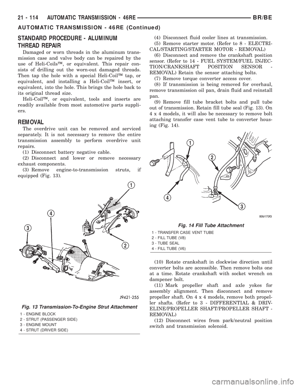
(3) Remove engine-to-transmission struts, if
equipped (Fig. 13).(4) Disconnect fluid cooler lines at transmission.
(5) Remove starter motor. (Refer to 8 - ELECTRI-
CAL/STARTING/STARTER MOTOR - REMOVAL)
(6) Disconnect and remove the crankshaft position
sensor. (Refer to 14 - FUEL SYSTEM/FUEL INJEC-
TION/CRANKSHAFT POSITION SENSOR -
REMOVAL) Retain the sensor attaching bolts.
(7) Remove torque converter access cover.
(8) If transmission is being removed for overhaul,
remove transmission oil pan, drain fluid and reinstall
pan.
(9) Remove fill tube bracket bolts and pull tube
out of transmission. Retain fill tube seal (Fig. 13). On
4 x 4 models, it will also be necessary to remove bolt
attaching transfer case vent tube to converter hous-
ing (Fig. 14).
(10) Rotate crankshaft in clockwise direction until
converter bolts are accessible. Then remove bolts one
at a time. Rotate crankshaft with socket wrench on
dampener bolt.
(11) Mark propeller shaft and axle yokes for
assembly alignment. Then disconnect and remove
propeller shaft. On4x4models, remove both propel-
ler shafts. (Refer to 3 - DIFFERENTIAL & DRIV-
ELINE/PROPELLER SHAFT/PROPELLER SHAFT -
REMOVAL)
(12) Disconnect wires from park/neutral position
switch and transmission solenoid.
Fig. 13 Transmission-To-Engine Strut Attachment
1 - ENGINE BLOCK
2 - STRUT (PASSENGER SIDE)
3 - ENGINE MOUNT
4 - STRUT (DRIVER SIDE)
Fig. 14 Fill Tube Attachment
1 - TRANSFER CASE VENT TUBE
2 - FILL TUBE (V8)
3 - TUBE SEAL
4 - FILL TUBE (V6)
21 - 114 AUTOMATIC TRANSMISSION - 46REBR/BE
AUTOMATIC TRANSMISSION - 46RE (Continued)
Page 1575 of 2255
CLEANING
Clean the case in a solvent tank. Flush the case
bores and fluid passages thoroughly with solvent.
Dry the case and all fluid passages with compressed
air. Be sure all solvent is removed from the case and
that all fluid passages are clear.
NOTE: Do not use shop towels or rags to dry the
case (or any other transmission component) unless
they are made from lint-free materials. Lint will stick
to case surfaces and transmission components and
circulate throughout the transmission after assem-
bly. A sufficient quantity of lint can block fluid pas-
sages and interfere with valve body operation.
Lubricate transmission parts with MopartATF +4,
type 9602, transmission fluid during overhaul and
assembly. Use petroleum jelly, MopartDoor Ease, or
Ru-GlydeŸ to prelubricate seals, O-rings, and thrust
washers. Petroleum jelly can also be used to hold
parts in place during reassembly.
INSPECTION
Inspect the case for cracks, porous spots, worn
bores, or damaged threads. Damaged threads can be
repaired with Helicoil thread inserts. However, the
case will have to be replaced if it exhibits any type of
damage or wear.
Lubricate the front band adjusting screw threads
with petroleum jelly and thread the screw part-way
into the case. Be sure the screw turns freely.Inspect the transmission bushings during overhaul.
Bushing condition is important as worn, scored bush-
ings contribute to low pressures, clutch slip and
accelerated wear of other components. However, do
not replace bushings as a matter of course. Replace
bushings only when they are actually worn, or
scored.
Use recommended tools to replace bushings. The
tools are sized and designed to remove, install, and
seat bushings correctly. The bushing replacement
tools are included in Bushing Tool Set C-3887-B.
Pre-sized service bushings are available for
replacement purposes. Only the sun gear bushings
are not serviced.
The use of crocus cloth is permissible where neces-
sary, providing it is used carefully. When used on
shafts, or valves, use extreme care to avoid rounding
off sharp edges. Sharp edges are vital as they pre-
vent foreign matter from getting between the valve
and valve bore.
Do not reuse oil seals, gaskets, seal rings, or
O-rings during overhaul. Replace these parts as a
matter of course. Also do not reuse snap rings or
E-clips that are bent or distorted. Replace these parts
as well.
ASSEMBLY
Do not allow dirt, grease, or foreign material to
enter the case or transmission components during
assembly. Keep the transmission case and compo-
nents clean. Also make sure the tools and workbench
area used for reassembly operations are equally
clean.
Shop towels used for wiping off tools and your
hands must be made fromlint freematerials. Lint
will stick to transmission parts and could interfere
with valve operation or even restrict fluid passages.
Lubricate transmission clutch and gear compo-
nents with MopartATF +4, type 9602, during reas-
sembly. Soak clutch discs in transmission fluid before
installation.
Use MopartDoor Ease, or Ru-GlydeŸ on piston
seals and O-rings to ease installation. Petroleum jelly
can also be used to lubricate and hold thrust washers
and plates in position during assembly.
Do not use chassis grease, bearing grease,
white grease, or similar lubricants on any part.
These types of lubricants can eventually block or
restrict fluid passages and valve operation. Use
petroleum jelly only.
Do not force parts into place. The transmission
components and sub-assemblies are easily installed
by hand when properly aligned. If a part seems dif-
ficult to install, it is either misaligned or incorrectly
assembled. Verify that thrust washers, thrust plates
and seal rings are correctly positioned.
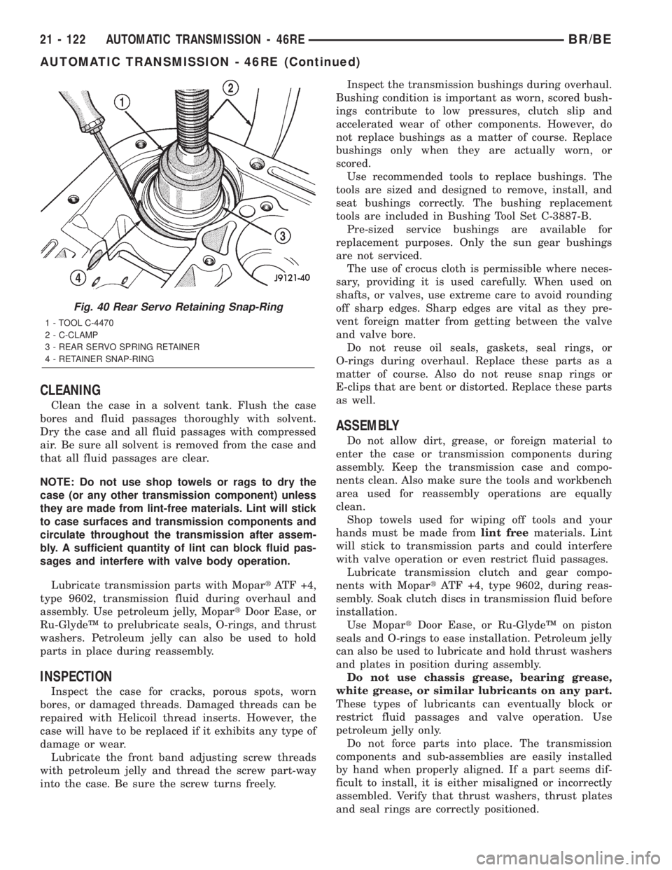
Fig. 40 Rear Servo Retaining Snap-Ring
1 - TOOL C-4470
2 - C-CLAMP
3 - REAR SERVO SPRING RETAINER
4 - RETAINER SNAP-RING
21 - 122 AUTOMATIC TRANSMISSION - 46REBR/BE
AUTOMATIC TRANSMISSION - 46RE (Continued)
Page 1576 of 2255

The planetary geartrain, front/rear clutch assem-
blies and oil pump are all much easier to install
when the transmission case is upright. Either tilt the
case upward with wood blocks, or cut a hole in the
bench large enough for the intermediate shaft and
rear support. Then lower the shaft and support into
the hole and support the rear of the case directly on
the bench.
FRONT/REAR SERVO
(1) Lubricate rear servo piston seal with Mopart
Door Ease or ATF +4. Lubricate servo bore in case
with ATF +4.
(2) Install rear servo piston in case. Position piston
at slight angle to bore and insert piston with twisting
motion (Fig. 41).
(3) Install rear servo spring and retainer in case
bore (Fig. 42). Be sure spring is seated on piston.
(4) Compress rear servo piston with C-clamp or
Valve Spring Compressor C-3422-B and install servo
piston snap-ring (Fig. 43).
(5) Lubricate front servo piston components and
servo bore in case with transmission fluid.
(6) Install front servo piston in bore. Carefully
ªrunº small, suitable tool around piston ring to press
it back into groove and ease installation (Fig. 44).
Rotate piston into bore at same time. Rock piston
slightly to ease piston ring past snap-ring groove and
into bore.
(7) Bottom front servo piston in bore and install
servo spring.
(8) Install front servo piston rod guide as follows:
(a) Place Tool SP-5560 (or similar size tool) on
guide and position C-clamp on tool and case (Fig.
45).(b) Slowly compress rod guide while simulta-
neously easing seal ring into bore with suitable
tool.
(9) Install rod guide snap-ring (Fig. 45).
Fig. 41 Rear Servo Piston
1 - REAR SERVO PISTON
Fig. 42 Rear Servo Piston Spring And Retainer
1 - PISTON SPRING
2 - REAR SERVO PISTON
3 - SPRING RETAINER
Fig. 43 Rear Servo Snap-Ring
1 - TOOL C-4470
2 - C-CLAMP
3 - REAR SERVO SPRING RETAINER
4 - RETAINER SNAP-RING
BR/BEAUTOMATIC TRANSMISSION - 46RE 21 - 123
AUTOMATIC TRANSMISSION - 46RE (Continued)
Page 1580 of 2255
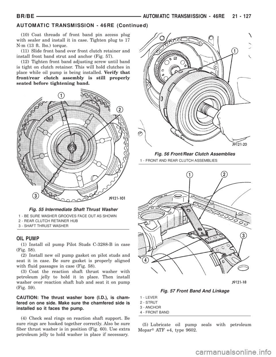
(10) Coat threads of front band pin access plug
with sealer and install it in case. Tighten plug to 17
N´m (13 ft. lbs.) torque.
(11) Slide front band over front clutch retainer and
install front band strut and anchor (Fig. 57).
(12) Tighten front band adjusting screw until band
is tight on clutch retainer. This will hold clutches in
place while oil pump is being installed.Verify that
front/rear clutch assembly is still properly
seated before tightening band.
OIL PUMP
(1) Install oil pump Pilot Studs C-3288-B in case
(Fig. 58).
(2) Install new oil pump gasket on pilot studs and
seat it in case. Be sure gasket is properly aligned
with fluid passages in case (Fig. 58).
(3) Coat the reaction shaft thrust washer with
petroleum jelly to hold it in place. Then install
washer over reaction shaft hub and seat it on pump
(Fig. 59).
CAUTION: The thrust washer bore (I.D.), is cham-
fered on one side. Make sure the chamfered side is
installed so it faces the pump.
(4) Check seal rings on reaction shaft support. Be
sure rings are hooked together correctly. Also be sure
fiber thrust washer is in position (Fig. 60). Use extra
petroleum jelly to hold washer in place if necessary.(5) Lubricate oil pump seals with petroleum
MopartATF +4, type 9602.
Fig. 55 Intermediate Shaft Thrust Washer
1 - BE SURE WASHER GROOVES FACE OUT AS SHOWN
2 - REAR CLUTCH RETAINER HUB
3 - SHAFT THRUST WASHER
Fig. 56 Front/Rear Clutch Assemblies
1 - FRONT AND REAR CLUTCH ASSEMBLIES
Fig. 57 Front Band And Linkage
1 - LEVER
2 - STRUT
3 - ANCHOR
4 - FRONT BAND
BR/BEAUTOMATIC TRANSMISSION - 46RE 21 - 127
AUTOMATIC TRANSMISSION - 46RE (Continued)
Page 1582 of 2255
INPUT SHAFT END PLAY CHECK
NOTE: Overdrive unit must be installed in order to
correctly measure the input shaft end-play.
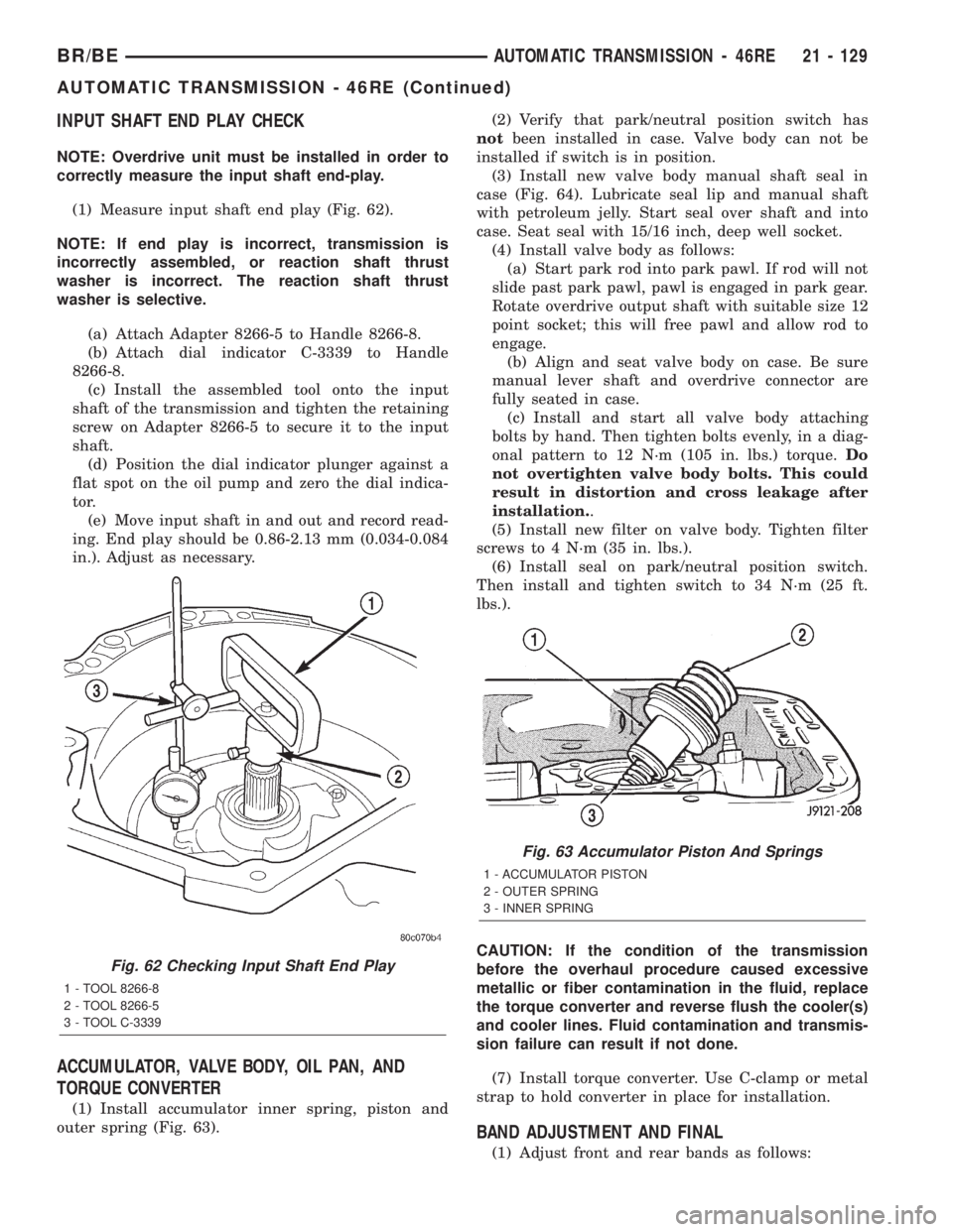
(1) Measure input shaft end play (Fig. 62).
NOTE: If end play is incorrect, transmission is
incorrectly assembled, or reaction shaft thrust
washer is incorrect. The reaction shaft thrust
washer is selective.
(a) Attach Adapter 8266-5 to Handle 8266-8.
(b) Attach dial indicator C-3339 to Handle
8266-8.
(c) Install the assembled tool onto the input
shaft of the transmission and tighten the retaining
screw on Adapter 8266-5 to secure it to the input
shaft.
(d) Position the dial indicator plunger against a
flat spot on the oil pump and zero the dial indica-
tor.
(e) Move input shaft in and out and record read-
ing. End play should be 0.86-2.13 mm (0.034-0.084
in.). Adjust as necessary.
ACCUMULATOR, VALVE BODY, OIL PAN, AND
TORQUE CONVERTER
(1) Install accumulator inner spring, piston and
outer spring (Fig. 63).(2) Verify that park/neutral position switch has
notbeen installed in case. Valve body can not be
installed if switch is in position.
(3) Install new valve body manual shaft seal in
case (Fig. 64). Lubricate seal lip and manual shaft
with petroleum jelly. Start seal over shaft and into
case. Seat seal with 15/16 inch, deep well socket.
(4) Install valve body as follows:
(a) Start park rod into park pawl. If rod will not
slide past park pawl, pawl is engaged in park gear.
Rotate overdrive output shaft with suitable size 12
point socket; this will free pawl and allow rod to
engage.
(b) Align and seat valve body on case. Be sure
manual lever shaft and overdrive connector are
fully seated in case.
(c) Install and start all valve body attaching
bolts by hand. Then tighten bolts evenly, in a diag-
onal pattern to 12 N´m (105 in. lbs.) torque.Do
not overtighten valve body bolts. This could
result in distortion and cross leakage after
installation..
(5) Install new filter on valve body. Tighten filter
screws to 4 N´m (35 in. lbs.).
(6) Install seal on park/neutral position switch.
Then install and tighten switch to 34 N´m (25 ft.
lbs.).
CAUTION: If the condition of the transmission
before the overhaul procedure caused excessive
metallic or fiber contamination in the fluid, replace
the torque converter and reverse flush the cooler(s)
and cooler lines. Fluid contamination and transmis-
sion failure can result if not done.
(7) Install torque converter. Use C-clamp or metal
strap to hold converter in place for installation.
BAND ADJUSTMENT AND FINAL
(1) Adjust front and rear bands as follows:
Fig. 62 Checking Input Shaft End Play
1 - TOOL 8266-8
2 - TOOL 8266-5
3 - TOOL C-3339
Fig. 63 Accumulator Piston And Springs
1 - ACCUMULATOR PISTON
2 - OUTER SPRING
3 - INNER SPRING
BR/BEAUTOMATIC TRANSMISSION - 46RE 21 - 129
AUTOMATIC TRANSMISSION - 46RE (Continued)