2002 DODGE RAM lock
[x] Cancel search: lockPage 1645 of 2255
OVERRUNNING CLUTCH
CAM/OVERDRIVE PISTON
RETAINER
DESCRIPTION
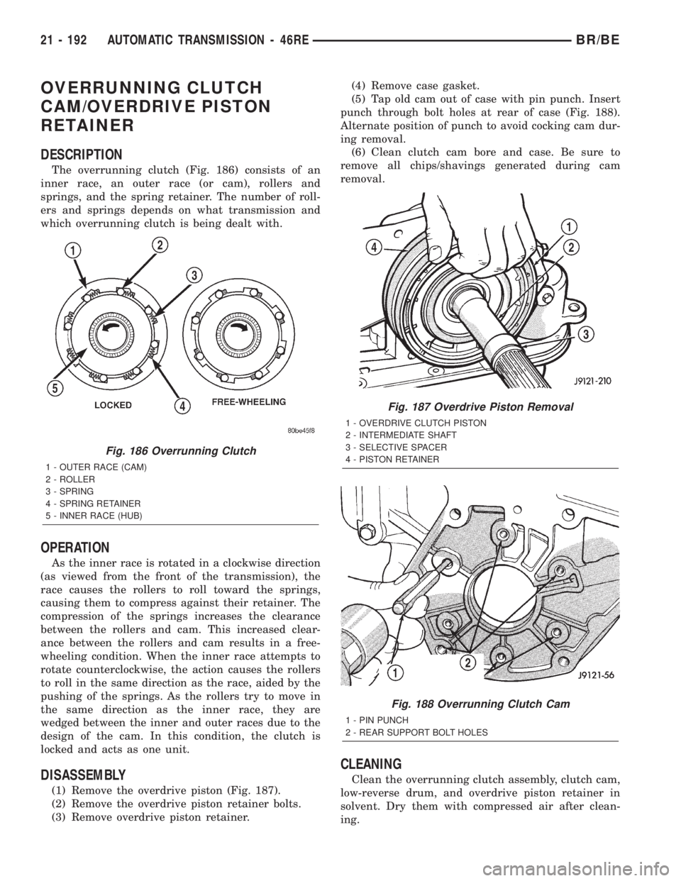
The overrunning clutch (Fig. 186) consists of an
inner race, an outer race (or cam), rollers and
springs, and the spring retainer. The number of roll-
ers and springs depends on what transmission and
which overrunning clutch is being dealt with.
OPERATION
As the inner race is rotated in a clockwise direction
(as viewed from the front of the transmission), the
race causes the rollers to roll toward the springs,
causing them to compress against their retainer. The
compression of the springs increases the clearance
between the rollers and cam. This increased clear-
ance between the rollers and cam results in a free-
wheeling condition. When the inner race attempts to
rotate counterclockwise, the action causes the rollers
to roll in the same direction as the race, aided by the
pushing of the springs. As the rollers try to move in
the same direction as the inner race, they are
wedged between the inner and outer races due to the
design of the cam. In this condition, the clutch is
locked and acts as one unit.
DISASSEMBLY
(1) Remove the overdrive piston (Fig. 187).
(2) Remove the overdrive piston retainer bolts.
(3) Remove overdrive piston retainer.(4) Remove case gasket.
(5) Tap old cam out of case with pin punch. Insert
punch through bolt holes at rear of case (Fig. 188).
Alternate position of punch to avoid cocking cam dur-
ing removal.
(6) Clean clutch cam bore and case. Be sure to
remove all chips/shavings generated during cam
removal.
CLEANING
Clean the overrunning clutch assembly, clutch cam,
low-reverse drum, and overdrive piston retainer in
solvent. Dry them with compressed air after clean-
ing.
Fig. 186 Overrunning Clutch
1 - OUTER RACE (CAM)
2 - ROLLER
3 - SPRING
4 - SPRING RETAINER
5 - INNER RACE (HUB)
Fig. 187 Overdrive Piston Removal
1 - OVERDRIVE CLUTCH PISTON
2 - INTERMEDIATE SHAFT
3 - SELECTIVE SPACER
4 - PISTON RETAINER
Fig. 188 Overrunning Clutch Cam
1 - PIN PUNCH
2 - REAR SUPPORT BOLT HOLES
21 - 192 AUTOMATIC TRANSMISSION - 46REBR/BE
Page 1649 of 2255
OPERATION
The principal which makes this operation possible
is known as Pascal's Law. Pascal's Law can be stated
as: ªPressure on a confined fluid is transmitted
equally in all directions and acts with equal force on
equal areas.º
PRESSURE
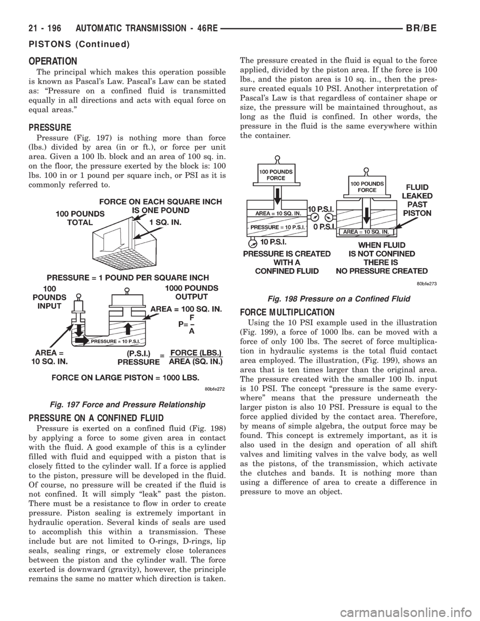
Pressure (Fig. 197) is nothing more than force
(lbs.) divided by area (in or ft.), or force per unit
area. Given a 100 lb. block and an area of 100 sq. in.
on the floor, the pressure exerted by the block is: 100
lbs. 100 in or 1 pound per square inch, or PSI as it is
commonly referred to.
PRESSURE ON A CONFINED FLUID
Pressure is exerted on a confined fluid (Fig. 198)
by applying a force to some given area in contact
with the fluid. A good example of this is a cylinder
filled with fluid and equipped with a piston that is
closely fitted to the cylinder wall. If a force is applied
to the piston, pressure will be developed in the fluid.
Of course, no pressure will be created if the fluid is
not confined. It will simply ªleakº past the piston.
There must be a resistance to flow in order to create
pressure. Piston sealing is extremely important in
hydraulic operation. Several kinds of seals are used
to accomplish this within a transmission. These
include but are not limited to O-rings, D-rings, lip
seals, sealing rings, or extremely close tolerances
between the piston and the cylinder wall. The force
exerted is downward (gravity), however, the principle
remains the same no matter which direction is taken.The pressure created in the fluid is equal to the force
applied, divided by the piston area. If the force is 100
lbs., and the piston area is 10 sq. in., then the pres-
sure created equals 10 PSI. Another interpretation of
Pascal's Law is that regardless of container shape or
size, the pressure will be maintained throughout, as
long as the fluid is confined. In other words, the
pressure in the fluid is the same everywhere within
the container.
FORCE MULTIPLICATION
Using the 10 PSI example used in the illustration
(Fig. 199), a force of 1000 lbs. can be moved with a
force of only 100 lbs. The secret of force multiplica-
tion in hydraulic systems is the total fluid contact
area employed. The illustration, (Fig. 199), shows an
area that is ten times larger than the original area.
The pressure created with the smaller 100 lb. input
is 10 PSI. The concept ªpressure is the same every-
whereº means that the pressure underneath the
larger piston is also 10 PSI. Pressure is equal to the
force applied divided by the contact area. Therefore,
by means of simple algebra, the output force may be
found. This concept is extremely important, as it is
also used in the design and operation of all shift
valves and limiting valves in the valve body, as well
as the pistons, of the transmission, which activate
the clutches and bands. It is nothing more than
using a difference of area to create a difference in
pressure to move an object.
Fig. 197 Force and Pressure Relationship
Fig. 198 Pressure on a Confined Fluid
21 - 196 AUTOMATIC TRANSMISSION - 46REBR/BE
PISTONS (Continued)
Page 1655 of 2255
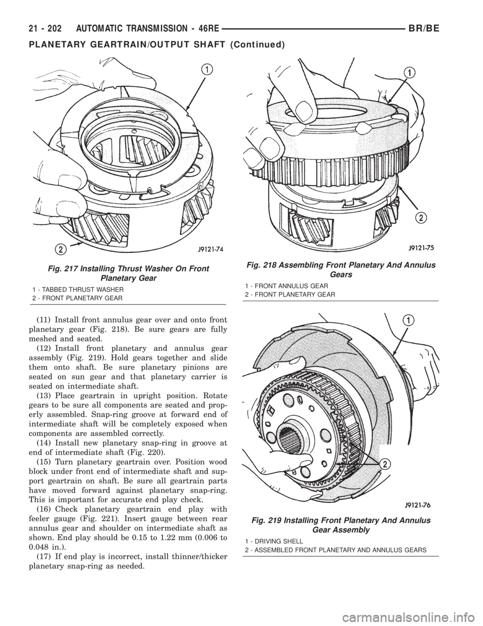
(11) Install front annulus gear over and onto front
planetary gear (Fig. 218). Be sure gears are fully
meshed and seated.
(12) Install front planetary and annulus gear
assembly (Fig. 219). Hold gears together and slide
them onto shaft. Be sure planetary pinions are
seated on sun gear and that planetary carrier is
seated on intermediate shaft.
(13) Place geartrain in upright position. Rotate
gears to be sure all components are seated and prop-
erly assembled. Snap-ring groove at forward end of
intermediate shaft will be completely exposed when
components are assembled correctly.
(14) Install new planetary snap-ring in groove at
end of intermediate shaft (Fig. 220).
(15) Turn planetary geartrain over. Position wood
block under front end of intermediate shaft and sup-
port geartrain on shaft. Be sure all geartrain parts
have moved forward against planetary snap-ring.
This is important for accurate end play check.
(16) Check planetary geartrain end play with
feeler gauge (Fig. 221). Insert gauge between rear
annulus gear and shoulder on intermediate shaft as
shown. End play should be 0.15 to 1.22 mm (0.006 to
0.048 in.).
(17) If end play is incorrect, install thinner/thicker
planetary snap-ring as needed.
Fig. 217 Installing Thrust Washer On Front
Planetary Gear
1 - TABBED THRUST WASHER
2 - FRONT PLANETARY GEAR
Fig. 218 Assembling Front Planetary And Annulus
Gears
1 - FRONT ANNULUS GEAR
2 - FRONT PLANETARY GEAR
Fig. 219 Installing Front Planetary And Annulus
Gear Assembly
1 - DRIVING SHELL
2 - ASSEMBLED FRONT PLANETARY AND ANNULUS GEARS
21 - 202 AUTOMATIC TRANSMISSION - 46REBR/BE
PLANETARY GEARTRAIN/OUTPUT SHAFT (Continued)
Page 1657 of 2255
DISASSEMBLY
(1) Remove fiber thrust washer from forward side
of clutch retainer.
(2) Remove input shaft front and rear seal rings.
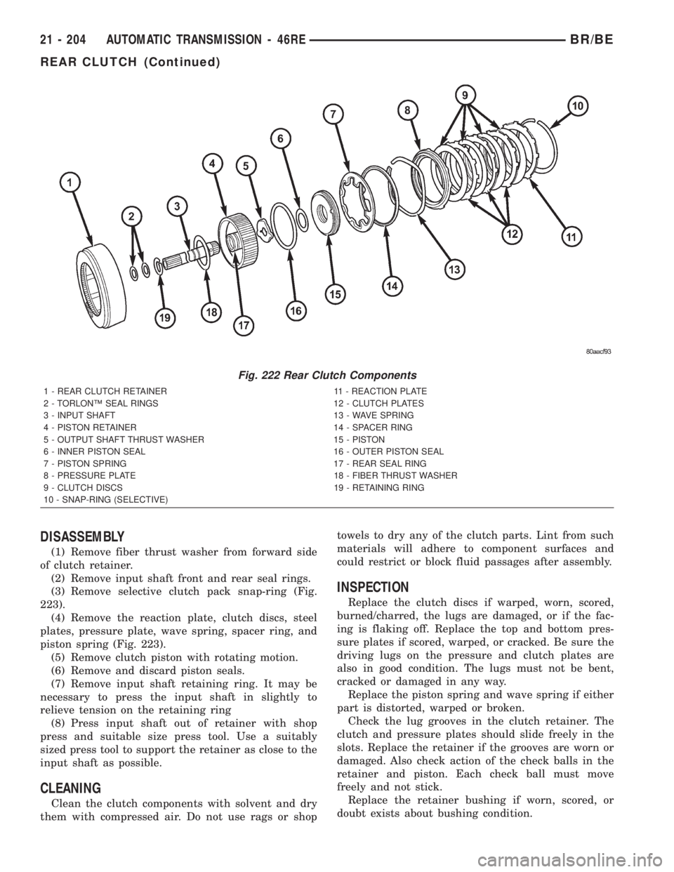
(3) Remove selective clutch pack snap-ring (Fig.
223).
(4) Remove the reaction plate, clutch discs, steel
plates, pressure plate, wave spring, spacer ring, and
piston spring (Fig. 223).
(5) Remove clutch piston with rotating motion.
(6) Remove and discard piston seals.
(7) Remove input shaft retaining ring. It may be
necessary to press the input shaft in slightly to
relieve tension on the retaining ring
(8) Press input shaft out of retainer with shop
press and suitable size press tool. Use a suitably
sized press tool to support the retainer as close to the
input shaft as possible.
CLEANING
Clean the clutch components with solvent and dry
them with compressed air. Do not use rags or shoptowels to dry any of the clutch parts. Lint from such
materials will adhere to component surfaces and
could restrict or block fluid passages after assembly.
INSPECTION
Replace the clutch discs if warped, worn, scored,
burned/charred, the lugs are damaged, or if the fac-
ing is flaking off. Replace the top and bottom pres-
sure plates if scored, warped, or cracked. Be sure the
driving lugs on the pressure and clutch plates are
also in good condition. The lugs must not be bent,
cracked or damaged in any way.
Replace the piston spring and wave spring if either
part is distorted, warped or broken.
Check the lug grooves in the clutch retainer. The
clutch and pressure plates should slide freely in the
slots. Replace the retainer if the grooves are worn or
damaged. Also check action of the check balls in the
retainer and piston. Each check ball must move
freely and not stick.
Replace the retainer bushing if worn, scored, or
doubt exists about bushing condition.
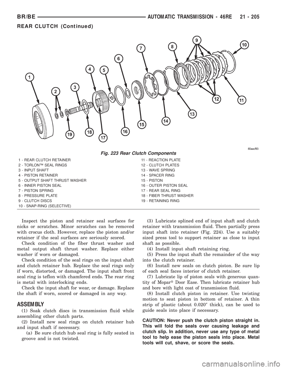
Fig. 222 Rear Clutch Components
1 - REAR CLUTCH RETAINER 11 - REACTION PLATE
2 - TORLONŸ SEAL RINGS 12 - CLUTCH PLATES
3 - INPUT SHAFT 13 - WAVE SPRING
4 - PISTON RETAINER 14 - SPACER RING
5 - OUTPUT SHAFT THRUST WASHER 15 - PISTON
6 - INNER PISTON SEAL 16 - OUTER PISTON SEAL
7 - PISTON SPRING 17 - REAR SEAL RING
8 - PRESSURE PLATE 18 - FIBER THRUST WASHER
9 - CLUTCH DISCS 19 - RETAINING RING
10 - SNAP-RING (SELECTIVE)
21 - 204 AUTOMATIC TRANSMISSION - 46REBR/BE
REAR CLUTCH (Continued)
Page 1658 of 2255
Inspect the piston and retainer seal surfaces for
nicks or scratches. Minor scratches can be removed
with crocus cloth. However, replace the piston and/or
retainer if the seal surfaces are seriously scored.
Check condition of the fiber thrust washer and
metal output shaft thrust washer. Replace either
washer if worn or damaged.
Check condition of the seal rings on the input shaft
and clutch retainer hub. Replace the seal rings only
if worn, distorted, or damaged. The input shaft front
seal ring is teflon with chamfered ends. The rear ring
is metal with interlocking ends.
Check the input shaft for wear, or damage. Replace
the shaft if worn, scored or damaged in any way.
ASSEMBLY
(1) Soak clutch discs in transmission fluid while
assembling other clutch parts.
(2) Install new seal rings on clutch retainer hub
and input shaft if necessary.
(a) Be sure clutch hub seal ring is fully seated in
groove and is not twisted.(3) Lubricate splined end of input shaft and clutch
retainer with transmission fluid. Then partially press
input shaft into retainer (Fig. 224). Use a suitably
sized press tool to support retainer as close to input
shaft as possible.
(4) Install input shaft retaining ring.
(5) Press the input shaft the remainder of the way
into the clutch retainer.
(6) Install new seals on clutch piston. Be sure lip
of each seal faces interior of clutch retainer.
(7)
Lubricate lip of piston seals with generous quan-
tity of MopartDoor Ease. Then lubricate retainer hub
and bore with light coat of transmission fluid.
(8) Install clutch piston in retainer. Use twisting
motion to seat piston in bottom of retainer. A thin
strip of plastic (about 0.0209thick), can be used to
guide seals into place if necessary.
CAUTION: Never push the clutch piston straight in.
This will fold the seals over causing leakage and
clutch slip. In addition, never use any type of metal
tool to help ease the piston seals into place. Metal
tools will cut, shave, or score the seals.
Fig. 223 Rear Clutch Components
1 - REAR CLUTCH RETAINER 11 - REACTION PLATE
2 - TORLONŸ SEAL RINGS 12 - CLUTCH PLATES
3 - INPUT SHAFT 13 - WAVE SPRING
4 - PISTON RETAINER 14 - SPACER RING
5 - OUTPUT SHAFT THRUST WASHER 15 - PISTON
6 - INNER PISTON SEAL 16 - OUTER PISTON SEAL
7 - PISTON SPRING 17 - REAR SEAL RING
8 - PRESSURE PLATE 18 - FIBER THRUST WASHER
9 - CLUTCH DISCS 19 - RETAINING RING
10 - SNAP-RING (SELECTIVE)
BR/BEAUTOMATIC TRANSMISSION - 46RE 21 - 205
REAR CLUTCH (Continued)
Page 1661 of 2255
SHIFT MECHANISM
DESCRIPTION
The gear shift mechanism provides six shift posi-
tions which are:
²PARK (P)
²REVERSE (R)
²NEUTRAL (N)
²DRIVE (D)
²Manual SECOND (2)
²Manual LOW (1)
OPERATION
Manual LOW (1) range provides first gear only.
Overrun braking is also provided in this range. Man-
ual SECOND (2) range provides first and second gear
only.
DRIVE range provides first, second third and over-
drive fourth gear ranges. The shift into overdrive
fourth gear range occurs only after the transmission
has completed the shift into D third gear range. No
further movement of the shift mechanism is required
to complete the 3-4 shift.
The fourth gear upshift occurs automatically when
the overdrive selector switch is in the ON position.
No upshift to fourth gear will occur if any of the fol-
lowing are true:
²The transmission fluid temperature is below 10É
C (50É F) or above 121É C (250É F).
²The shift to third is not yet complete.
²Vehicle speed is too low for the 3-4 shift to occur.
²Battery temperature is below -5É C (23É F).
ADJUSTMENTS
ADJUSTMENT
Check linkage adjustment by starting engine in
PARK and NEUTRAL. Adjustment is acceptable if
the engine starts in only these two positions. Adjust-
ment is incorrect if the engine starts in one position
but not both positions
If the engine starts in any other position, or if the
engine will not start in any position, the park/neutral
switch is probably faulty.
LINKAGE ADJUSTMENT
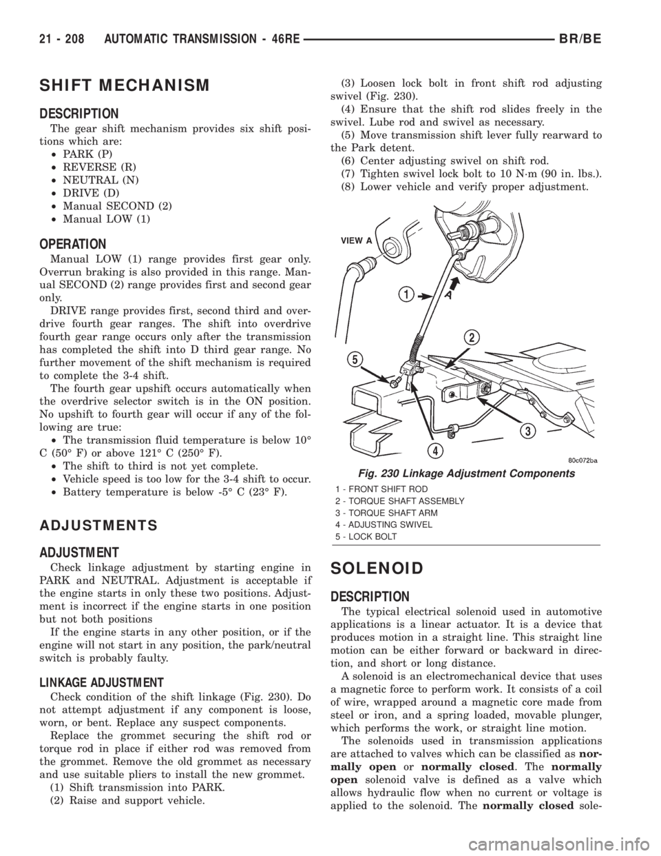
Check condition of the shift linkage (Fig. 230). Do
not attempt adjustment if any component is loose,
worn, or bent. Replace any suspect components.
Replace the grommet securing the shift rod or
torque rod in place if either rod was removed from
the grommet. Remove the old grommet as necessary
and use suitable pliers to install the new grommet.
(1) Shift transmission into PARK.
(2) Raise and support vehicle.(3) Loosen lock bolt in front shift rod adjusting
swivel (Fig. 230).
(4) Ensure that the shift rod slides freely in the
swivel. Lube rod and swivel as necessary.
(5) Move transmission shift lever fully rearward to
the Park detent.
(6) Center adjusting swivel on shift rod.
(7) Tighten swivel lock bolt to 10 N´m (90 in. lbs.).
(8) Lower vehicle and verify proper adjustment.
SOLENOID
DESCRIPTION
The typical electrical solenoid used in automotive
applications is a linear actuator. It is a device that
produces motion in a straight line. This straight line
motion can be either forward or backward in direc-
tion, and short or long distance.
A solenoid is an electromechanical device that uses
a magnetic force to perform work. It consists of a coil
of wire, wrapped around a magnetic core made from
steel or iron, and a spring loaded, movable plunger,
which performs the work, or straight line motion.
The solenoids used in transmission applications
are attached to valves which can be classified asnor-
mally openornormally closed. Thenormally
opensolenoid valve is defined as a valve which
allows hydraulic flow when no current or voltage is
applied to the solenoid. Thenormally closedsole-
Fig. 230 Linkage Adjustment Components
1 - FRONT SHIFT ROD
2 - TORQUE SHAFT ASSEMBLY
3 - TORQUE SHAFT ARM
4 - ADJUSTING SWIVEL
5 - LOCK BOLT
21 - 208 AUTOMATIC TRANSMISSION - 46REBR/BE
Page 1662 of 2255
noid valve is defined as a valve which does not allow
hydraulic flow when no current or voltage is applied
to the solenoid. These valves perform hydraulic con-
trol functions for the transmission and must there-
fore be durable and tolerant of dirt particles. For
these reasons, the valves have hardened steel pop-
pets and ball valves. The solenoids operate the valves
directly, which means that the solenoids must have
very high outputs to close the valves against the siz-
able flow areas and line pressures found in current
transmissions. Fast response time is also necessary
to ensure accurate control of the transmission.
The strength of the magnetic field is the primary
force that determines the speed of operation in a par-
ticular solenoid design. A stronger magnetic field will
cause the plunger to move at a greater speed than a
weaker one. There are basically two ways to increase
the force of the magnetic field:
²Increase the amount of current applied to the
coil or
²Increase the number of turns of wire in the coil.
The most common practice is to increase the num-
ber of turns by using thin wire that can completely
fill the available space within the solenoid housing.
The strength of the spring and the length of the
plunger also contribute to the response speed possi-
ble by a particular solenoid design.
A solenoid can also be described by the method by
which it is controlled. Some of the possibilities
include variable force, pulse-width modulated, con-
stant ON, or duty cycle. The variable force and pulse-
width modulated versions utilize similar methods to
control the current flow through the solenoid to posi-
tion the solenoid plunger at a desired position some-
where between full ON and full OFF. The constant
ON and duty cycled versions control the voltage
across the solenoid to allow either full flow or no flow
through the solenoid's valve.
OPERATION
When an electrical current is applied to the sole-
noid coil, a magnetic field is created which produces
an attraction to the plunger, causing the plunger to
move and work against the spring pressure and the
load applied by the fluid the valve is controlling. The
plunger is normally directly attached to the valve
which it is to operate. When the current is removed
from the coil, the attraction is removed and the
plunger will return to its original position due to
spring pressure.
The plunger is made of a conductive material and
accomplishes this movement by providing a path for
the magnetic field to flow. By keeping the air gap
between the plunger and the coil to the minimum
necessary to allow free movement of the plunger, the
magnetic field is maximized.
SPEED SENSOR
DESCRIPTION
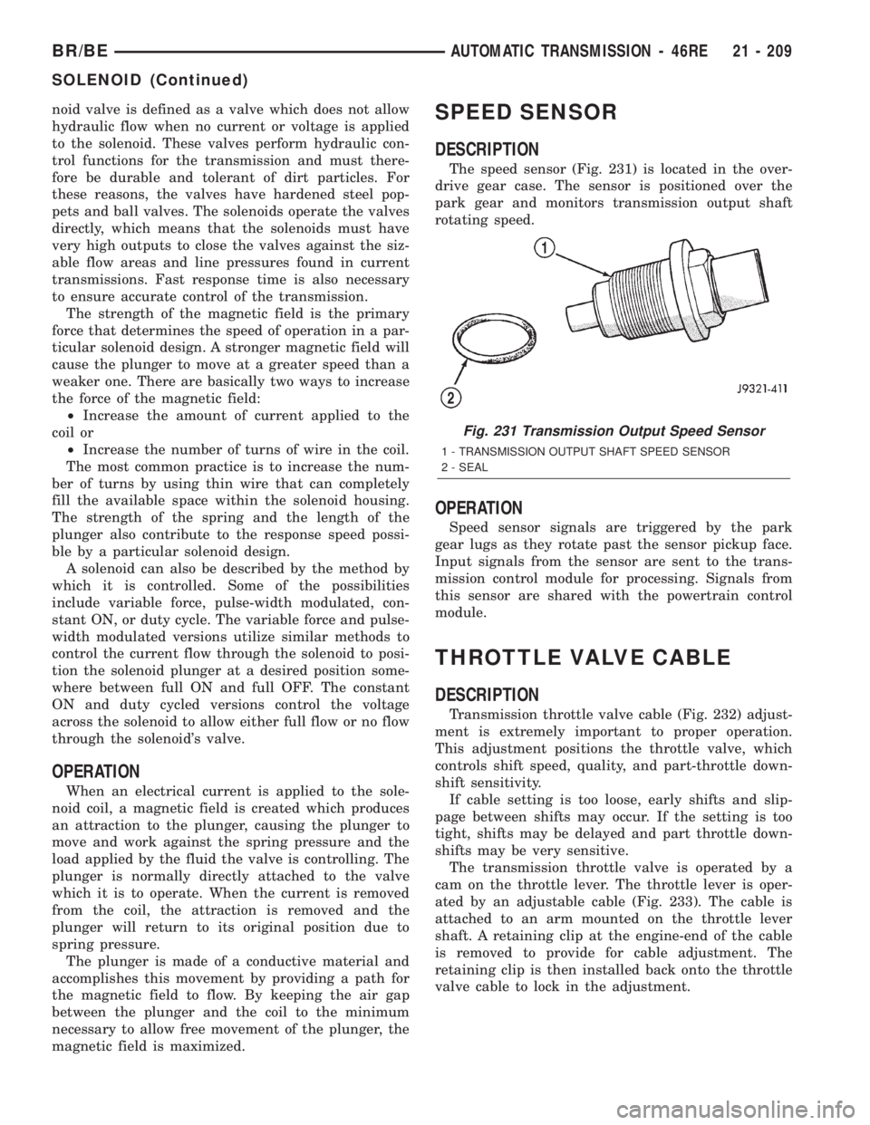
The speed sensor (Fig. 231) is located in the over-
drive gear case. The sensor is positioned over the
park gear and monitors transmission output shaft
rotating speed.
OPERATION
Speed sensor signals are triggered by the park
gear lugs as they rotate past the sensor pickup face.
Input signals from the sensor are sent to the trans-
mission control module for processing. Signals from
this sensor are shared with the powertrain control
module.
THROTTLE VALVE CABLE
DESCRIPTION
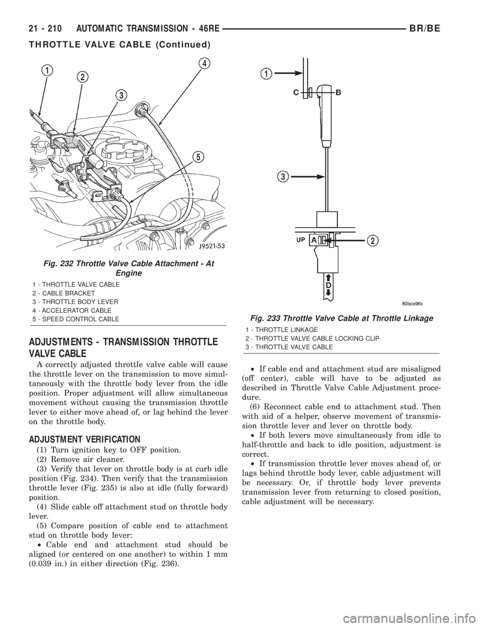
Transmission throttle valve cable (Fig. 232) adjust-
ment is extremely important to proper operation.
This adjustment positions the throttle valve, which
controls shift speed, quality, and part-throttle down-
shift sensitivity.
If cable setting is too loose, early shifts and slip-
page between shifts may occur. If the setting is too
tight, shifts may be delayed and part throttle down-
shifts may be very sensitive.
The transmission throttle valve is operated by a
cam on the throttle lever. The throttle lever is oper-
ated by an adjustable cable (Fig. 233). The cable is
attached to an arm mounted on the throttle lever
shaft. A retaining clip at the engine-end of the cable
is removed to provide for cable adjustment. The
retaining clip is then installed back onto the throttle
valve cable to lock in the adjustment.
Fig. 231 Transmission Output Speed Sensor
1 - TRANSMISSION OUTPUT SHAFT SPEED SENSOR
2 - SEAL
BR/BEAUTOMATIC TRANSMISSION - 46RE 21 - 209
SOLENOID (Continued)
Page 1663 of 2255
ADJUSTMENTS - TRANSMISSION THROTTLE
VALVE CABLE
A correctly adjusted throttle valve cable will cause
the throttle lever on the transmission to move simul-
taneously with the throttle body lever from the idle
position. Proper adjustment will allow simultaneous
movement without causing the transmission throttle
lever to either move ahead of, or lag behind the lever
on the throttle body.
ADJUSTMENT VERIFICATION
(1) Turn ignition key to OFF position.
(2) Remove air cleaner.
(3) Verify that lever on throttle body is at curb idle
position (Fig. 234). Then verify that the transmission
throttle lever (Fig. 235) is also at idle (fully forward)
position.
(4) Slide cable off attachment stud on throttle body
lever.
(5) Compare position of cable end to attachment
stud on throttle body lever:
²Cable end and attachment stud should be
aligned (or centered on one another) to within 1 mm
(0.039 in.) in either direction (Fig. 236).²If cable end and attachment stud are misaligned
(off center), cable will have to be adjusted as
described in Throttle Valve Cable Adjustment proce-
dure.
(6) Reconnect cable end to attachment stud. Then
with aid of a helper, observe movement of transmis-
sion throttle lever and lever on throttle body.
²If both levers move simultaneously from idle to
half-throttle and back to idle position, adjustment is
correct.
²If transmission throttle lever moves ahead of, or
lags behind throttle body lever, cable adjustment will
be necessary. Or, if throttle body lever prevents
transmission lever from returning to closed position,
cable adjustment will be necessary.
Fig. 232 Throttle Valve Cable Attachment - At
Engine
1 - THROTTLE VALVE CABLE
2 - CABLE BRACKET
3 - THROTTLE BODY LEVER
4 - ACCELERATOR CABLE
5 - SPEED CONTROL CABLE
Fig. 233 Throttle Valve Cable at Throttle Linkage
1 - THROTTLE LINKAGE
2 - THROTTLE VALVE CABLE LOCKING CLIP
3 - THROTTLE VALVE CABLE
21 - 210 AUTOMATIC TRANSMISSION - 46REBR/BE
THROTTLE VALVE CABLE (Continued)