2002 DODGE RAM lock
[x] Cancel search: lockPage 1579 of 2255
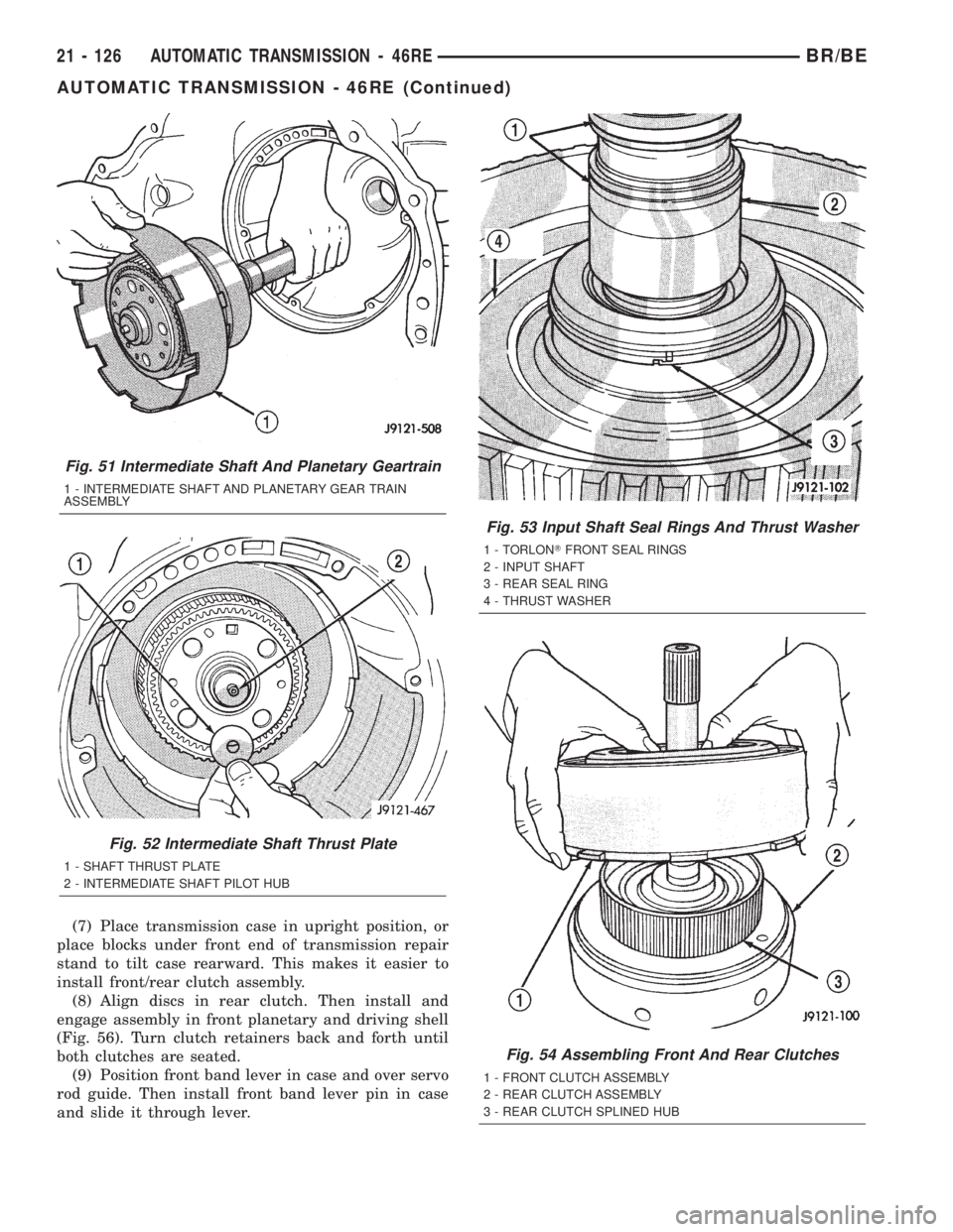
(7) Place transmission case in upright position, or
place blocks under front end of transmission repair
stand to tilt case rearward. This makes it easier to
install front/rear clutch assembly.
(8) Align discs in rear clutch. Then install and
engage assembly in front planetary and driving shell
(Fig. 56). Turn clutch retainers back and forth until
both clutches are seated.
(9) Position front band lever in case and over servo
rod guide. Then install front band lever pin in case
and slide it through lever.
Fig. 51 Intermediate Shaft And Planetary Geartrain
1 - INTERMEDIATE SHAFT AND PLANETARY GEAR TRAIN
ASSEMBLY
Fig. 52 Intermediate Shaft Thrust Plate
1 - SHAFT THRUST PLATE
2 - INTERMEDIATE SHAFT PILOT HUB
Fig. 53 Input Shaft Seal Rings And Thrust Washer
1 - TORLONTFRONT SEAL RINGS
2 - INPUT SHAFT
3 - REAR SEAL RING
4 - THRUST WASHER
Fig. 54 Assembling Front And Rear Clutches
1 - FRONT CLUTCH ASSEMBLY
2 - REAR CLUTCH ASSEMBLY
3 - REAR CLUTCH SPLINED HUB
21 - 126 AUTOMATIC TRANSMISSION - 46REBR/BE
AUTOMATIC TRANSMISSION - 46RE (Continued)
Page 1583 of 2255
(a) Loosen locknut on each band adjusting screw
4-5 turns.
(b) Tighten both adjusting screws to 8 N´m (72
in. lbs.).
(c) Back off front band adjusting screw 2-7/8
turns.
(d) Back off rear band adjusting screw 2 turns.
(e) Hold each adjusting screw in position and
tighten locknut to 34 N´m (25 ft. lbs.) torque.
(2) Install magnet in oil pan. Magnet seats on
small protrusion at corner of pan.
(3) Position new oil pan gasket on case and install
oil pan. Tighten pan bolts to 13.6 N´m (125 in. lbs.).
(4) Install throttle valve and shift selector levers
on valve body manual lever shaft.
(5) Apply small quantity of dielectric grease to ter-
minal pins of solenoid case connector and neutral
switch.
(6) Fill transmission with recommended fluid.
Refer to Service Procedures section of this group.
INSTALLATION
(1) Check torque converter hub and hub drive
notches for sharp edges burrs, scratches, or nicks.
Polish the hub and notches with 320/400 grit paper
and crocus cloth if necessary. The hub must be
smooth to avoid damaging pump seal at installation.
(2) Lubricate pocket in the rear oil pump seal lip
with transmission fluid.(3) Lubricate converter pilot hub of the crankshaft
with a light coating of MopartHigh Temp Grease.
(4) Align and install converter in oil pump.
(5) Carefully insert converter in oil pump. Then
rotate converter back and forth until fully seated in
pump gears.
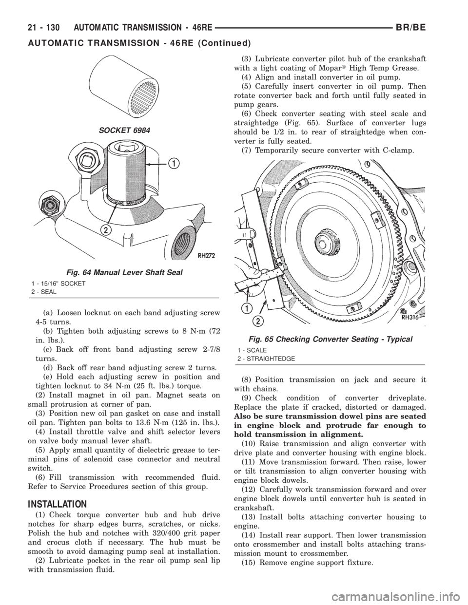
(6) Check converter seating with steel scale and
straightedge (Fig. 65). Surface of converter lugs
should be 1/2 in. to rear of straightedge when con-
verter is fully seated.
(7) Temporarily secure converter with C-clamp.
(8) Position transmission on jack and secure it
with chains.
(9) Check condition of converter driveplate.
Replace the plate if cracked, distorted or damaged.
Also be sure transmission dowel pins are seated
in engine block and protrude far enough to
hold transmission in alignment.
(10) Raise transmission and align converter with
drive plate and converter housing with engine block.
(11) Move transmission forward. Then raise, lower
or tilt transmission to align converter housing with
engine block dowels.
(12) Carefully work transmission forward and over
engine block dowels until converter hub is seated in
crankshaft.
(13) Install bolts attaching converter housing to
engine.
(14) Install rear support. Then lower transmission
onto crossmember and install bolts attaching trans-
mission mount to crossmember.
(15) Remove engine support fixture.
SOCKET 6984
Fig. 64 Manual Lever Shaft Seal
1 - 15/16©© SOCKET
2 - SEAL
Fig. 65 Checking Converter Seating - Typical
1 - SCALE
2 - STRAIGHTEDGE
21 - 130 AUTOMATIC TRANSMISSION - 46REBR/BE
AUTOMATIC TRANSMISSION - 46RE (Continued)
Page 1598 of 2255
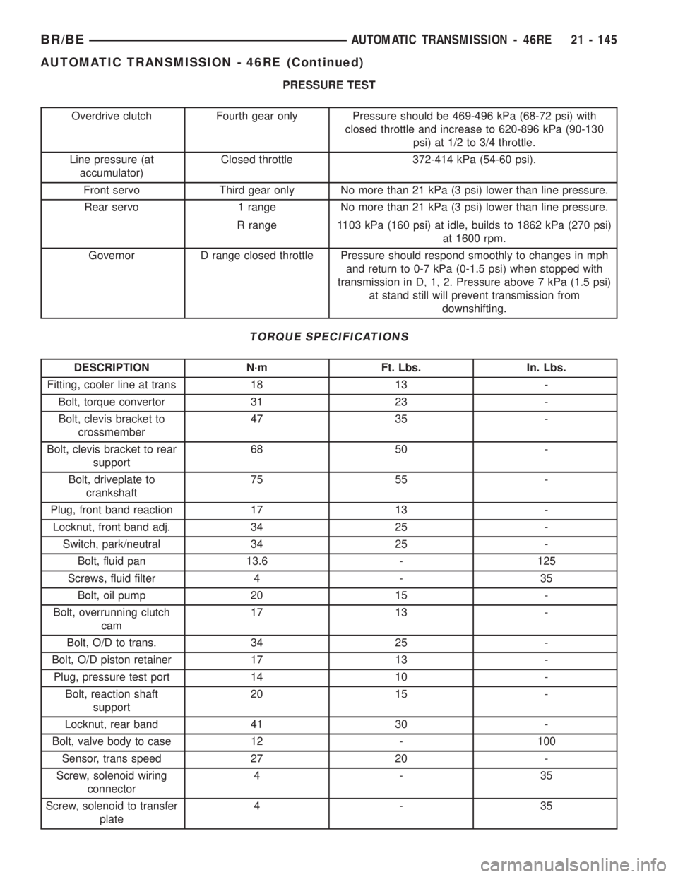
PRESSURE TEST
Overdrive clutch Fourth gear only Pressure should be 469-496 kPa (68-72 psi) with
closed throttle and increase to 620-896 kPa (90-130
psi) at 1/2 to 3/4 throttle.
Line pressure (at
accumulator)Closed throttle 372-414 kPa (54-60 psi).
Front servo Third gear only No more than 21 kPa (3 psi) lower than line pressure.
Rear servo 1 range No more than 21 kPa (3 psi) lower than line pressure.
R range 1103 kPa (160 psi) at idle, builds to 1862 kPa (270 psi)
at 1600 rpm.
Governor D range closed throttle Pressure should respond smoothly to changes in mph
and return to 0-7 kPa (0-1.5 psi) when stopped with
transmission in D, 1, 2. Pressure above 7 kPa (1.5 psi)
at stand still will prevent transmission from
downshifting.
TORQUE SPECIFICATIONS
DESCRIPTION N´m Ft. Lbs. In. Lbs.
Fitting, cooler line at trans 18 13 -
Bolt, torque convertor 31 23 -
Bolt, clevis bracket to
crossmember47 35 -
Bolt, clevis bracket to rear
support68 50 -
Bolt, driveplate to
crankshaft75 55 -
Plug, front band reaction 17 13 -
Locknut, front band adj. 34 25 -
Switch, park/neutral 34 25 -
Bolt, fluid pan 13.6 - 125
Screws, fluid filter 4 - 35
Bolt, oil pump 20 15 -
Bolt, overrunning clutch
cam17 13 -
Bolt, O/D to trans. 34 25 -
Bolt, O/D piston retainer 17 13 -
Plug, pressure test port 14 10 -
Bolt, reaction shaft
support20 15 -
Locknut, rear band 41 30 -
Bolt, valve body to case 12 - 100
Sensor, trans speed 27 20 -
Screw, solenoid wiring
connector4-35
Screw, solenoid to transfer
plate4-35
BR/BEAUTOMATIC TRANSMISSION - 46RE 21 - 145
AUTOMATIC TRANSMISSION - 46RE (Continued)
Page 1599 of 2255
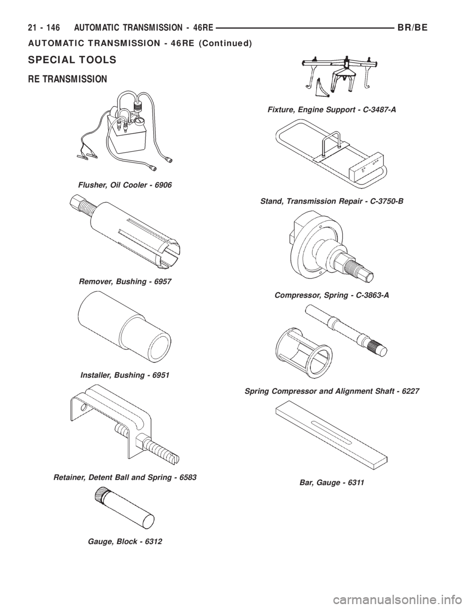
SPECIAL TOOLS
RE TRANSMISSION
Flusher, Oil Cooler - 6906
Remover, Bushing - 6957
Installer, Bushing - 6951
Retainer, Detent Ball and Spring - 6583
Gauge, Block - 6312
Fixture, Engine Support - C-3487-A
Stand, Transmission Repair - C-3750-B
Compressor, Spring - C-3863-A
Spring Compressor and Alignment Shaft - 6227
Bar, Gauge - 6311
21 - 146 AUTOMATIC TRANSMISSION - 46REBR/BE
AUTOMATIC TRANSMISSION - 46RE (Continued)
Page 1604 of 2255
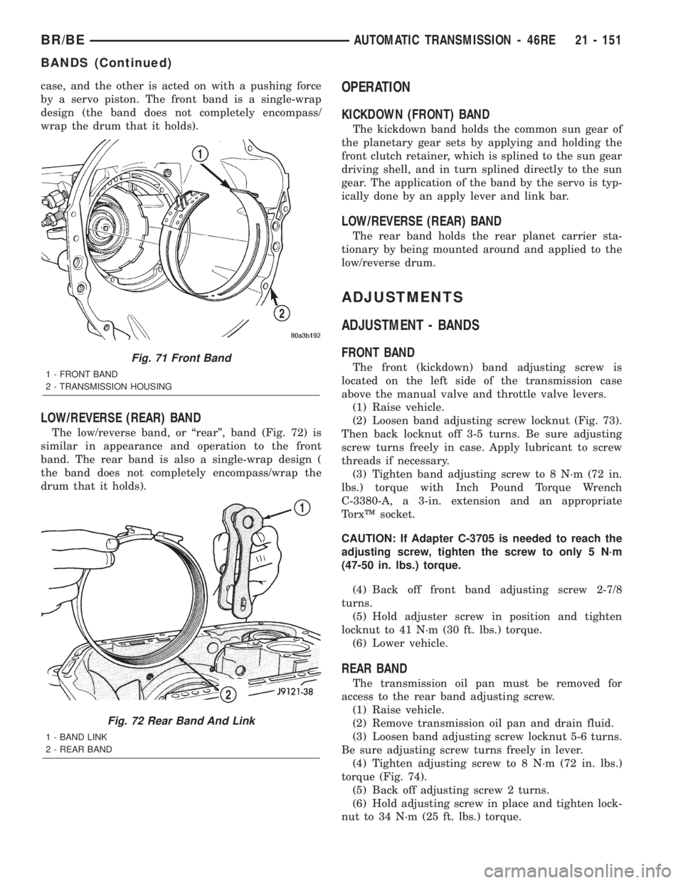
case, and the other is acted on with a pushing force
by a servo piston. The front band is a single-wrap
design (the band does not completely encompass/
wrap the drum that it holds).
LOW/REVERSE (REAR) BAND
The low/reverse band, or ªrearº, band (Fig. 72) is
similar in appearance and operation to the front
band. The rear band is also a single-wrap design (
the band does not completely encompass/wrap the
drum that it holds).
OPERATION
KICKDOWN (FRONT) BAND
The kickdown band holds the common sun gear of
the planetary gear sets by applying and holding the
front clutch retainer, which is splined to the sun gear
driving shell, and in turn splined directly to the sun
gear. The application of the band by the servo is typ-
ically done by an apply lever and link bar.
LOW/REVERSE (REAR) BAND
The rear band holds the rear planet carrier sta-
tionary by being mounted around and applied to the
low/reverse drum.
ADJUSTMENTS
ADJUSTMENT - BANDS
FRONT BAND
The front (kickdown) band adjusting screw is
located on the left side of the transmission case
above the manual valve and throttle valve levers.
(1) Raise vehicle.
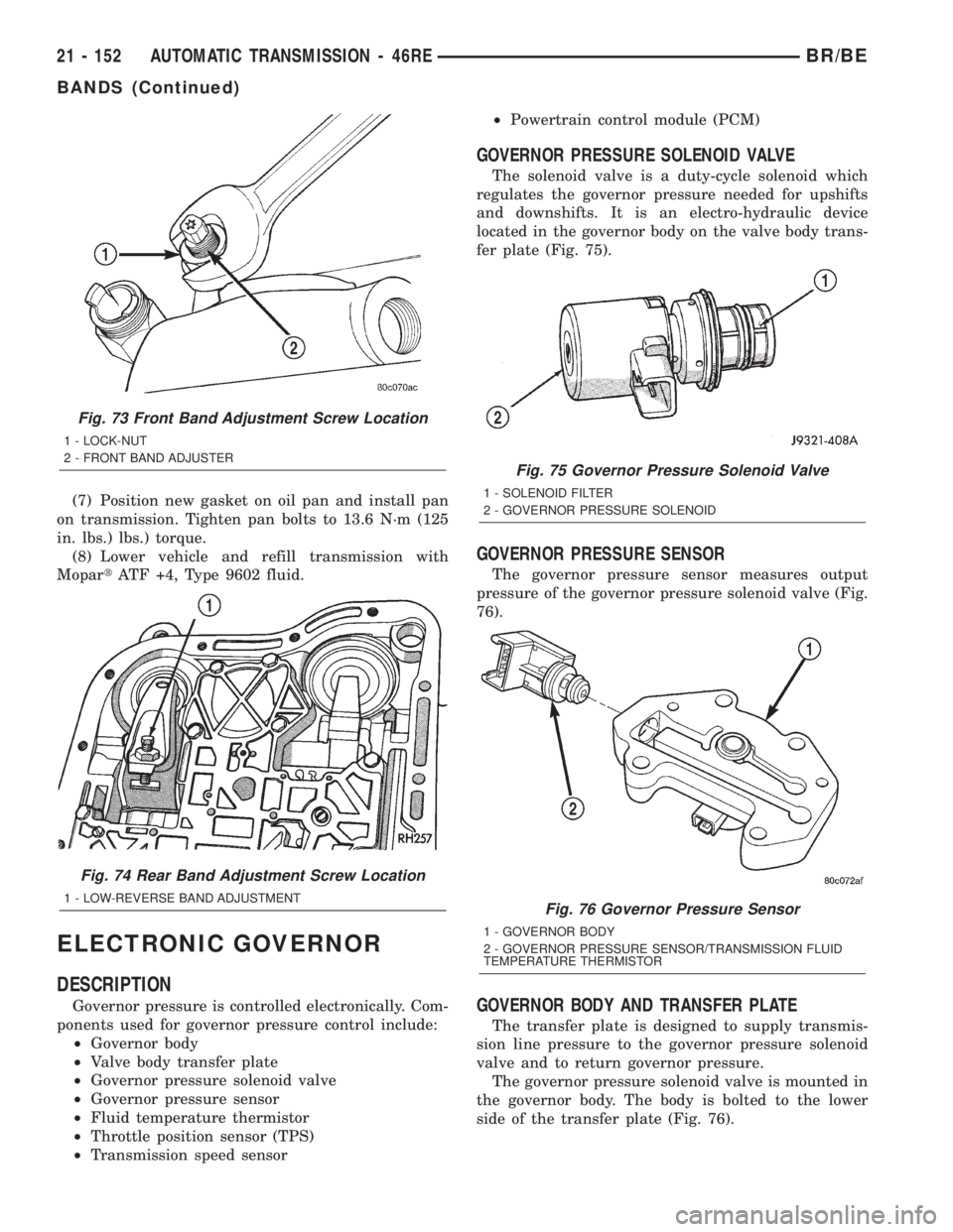
(2) Loosen band adjusting screw locknut (Fig. 73).
Then back locknut off 3-5 turns. Be sure adjusting
screw turns freely in case. Apply lubricant to screw
threads if necessary.
(3) Tighten band adjusting screw to 8 N´m (72 in.
lbs.) torque with Inch Pound Torque Wrench
C-3380-A, a 3-in. extension and an appropriate
TorxŸ socket.
CAUTION: If Adapter C-3705 is needed to reach the
adjusting screw, tighten the screw to only 5 N´m
(47-50 in. lbs.) torque.
(4) Back off front band adjusting screw 2-7/8
turns.
(5) Hold adjuster screw in position and tighten
locknut to 41 N´m (30 ft. lbs.) torque.
(6) Lower vehicle.
REAR BAND
The transmission oil pan must be removed for
access to the rear band adjusting screw.
(1) Raise vehicle.
(2) Remove transmission oil pan and drain fluid.
(3) Loosen band adjusting screw locknut 5-6 turns.
Be sure adjusting screw turns freely in lever.
(4) Tighten adjusting screw to 8 N´m (72 in. lbs.)
torque (Fig. 74).
(5) Back off adjusting screw 2 turns.
(6) Hold adjusting screw in place and tighten lock-
nut to 34 N´m (25 ft. lbs.) torque.
Fig. 71 Front Band
1 - FRONT BAND
2 - TRANSMISSION HOUSING
Fig. 72 Rear Band And Link
1 - BAND LINK
2 - REAR BAND
BR/BEAUTOMATIC TRANSMISSION - 46RE 21 - 151
BANDS (Continued)
Page 1605 of 2255
(7) Position new gasket on oil pan and install pan
on transmission. Tighten pan bolts to 13.6 N´m (125
in. lbs.) lbs.) torque.
(8) Lower vehicle and refill transmission with
MopartATF +4, Type 9602 fluid.
ELECTRONIC GOVERNOR
DESCRIPTION
Governor pressure is controlled electronically. Com-
ponents used for governor pressure control include:
²Governor body
²Valve body transfer plate
²Governor pressure solenoid valve
²Governor pressure sensor
²Fluid temperature thermistor
²Throttle position sensor (TPS)
²Transmission speed sensor²Powertrain control module (PCM)
GOVERNOR PRESSURE SOLENOID VALVE
The solenoid valve is a duty-cycle solenoid which
regulates the governor pressure needed for upshifts
and downshifts. It is an electro-hydraulic device
located in the governor body on the valve body trans-
fer plate (Fig. 75).
GOVERNOR PRESSURE SENSOR
The governor pressure sensor measures output
pressure of the governor pressure solenoid valve (Fig.
76).
GOVERNOR BODY AND TRANSFER PLATE
The transfer plate is designed to supply transmis-
sion line pressure to the governor pressure solenoid
valve and to return governor pressure.
The governor pressure solenoid valve is mounted in
the governor body. The body is bolted to the lower
side of the transfer plate (Fig. 76).
Fig. 73 Front Band Adjustment Screw Location
1 - LOCK-NUT
2 - FRONT BAND ADJUSTER
Fig. 74 Rear Band Adjustment Screw Location
1 - LOW-REVERSE BAND ADJUSTMENT
Fig. 75 Governor Pressure Solenoid Valve
1 - SOLENOID FILTER
2 - GOVERNOR PRESSURE SOLENOID
Fig. 76 Governor Pressure Sensor
1 - GOVERNOR BODY
2 - GOVERNOR PRESSURE SENSOR/TRANSMISSION FLUID
TEMPERATURE THERMISTOR
21 - 152 AUTOMATIC TRANSMISSION - 46REBR/BE
BANDS (Continued)
Page 1620 of 2255
(2) Run the engineat curb idle speed, with the
shift selector in neutral.
(3) If one quart of transmission fluid is collected in
the container in 20 seconds or less, oil pump flow vol-
ume is within acceptable limits. If fluid flow is inter-
mittent, or it takes more than 20 seconds to collect
one quart of fluid, refer to the Hydraulic Pressure
tests in this section for further diagnosis.
(4) Re-connect theTo coolerline to the transmis-
sion cooler inlet.
(5) Refill the transmission to proper level.
DISASSEMBLY
(1) Mark position of support in oil pump body for
assembly alignment reference. Use scriber or paint to
make alignment marks.
(2) Place pump body on two wood blocks.
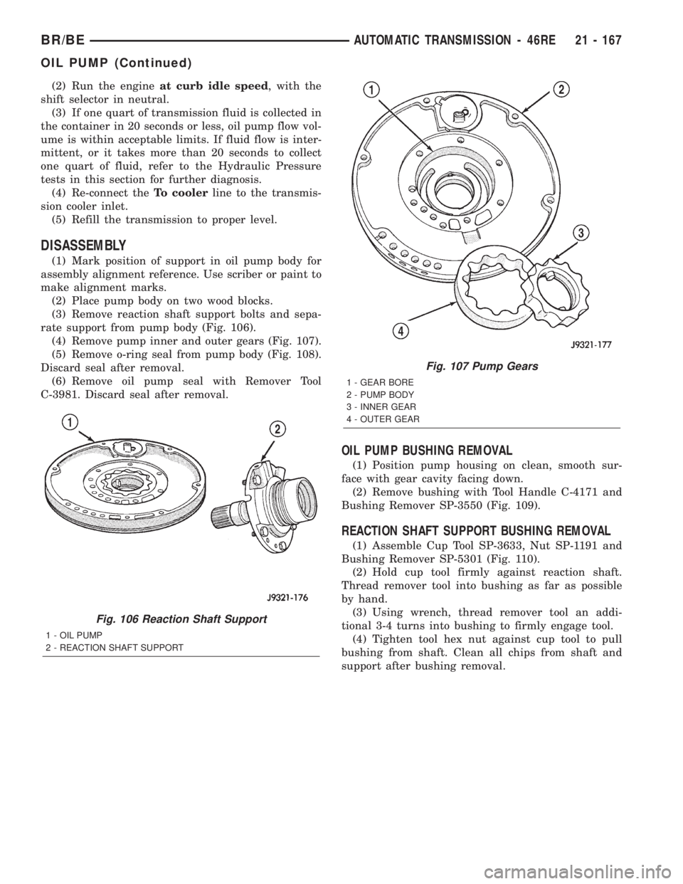
(3) Remove reaction shaft support bolts and sepa-
rate support from pump body (Fig. 106).
(4) Remove pump inner and outer gears (Fig. 107).
(5) Remove o-ring seal from pump body (Fig. 108).
Discard seal after removal.
(6) Remove oil pump seal with Remover Tool
C-3981. Discard seal after removal.
OIL PUMP BUSHING REMOVAL
(1) Position pump housing on clean, smooth sur-
face with gear cavity facing down.
(2) Remove bushing with Tool Handle C-4171 and
Bushing Remover SP-3550 (Fig. 109).
REACTION SHAFT SUPPORT BUSHING REMOVAL
(1) Assemble Cup Tool SP-3633, Nut SP-1191 and
Bushing Remover SP-5301 (Fig. 110).
(2) Hold cup tool firmly against reaction shaft.
Thread remover tool into bushing as far as possible
by hand.
(3) Using wrench, thread remover tool an addi-
tional 3-4 turns into bushing to firmly engage tool.
(4) Tighten tool hex nut against cup tool to pull
bushing from shaft. Clean all chips from shaft and
support after bushing removal.
Fig. 106 Reaction Shaft Support
1 - OIL PUMP
2 - REACTION SHAFT SUPPORT
Fig. 107 Pump Gears
1 - GEAR BORE
2 - PUMP BODY
3 - INNER GEAR
4 - OUTER GEAR
BR/BEAUTOMATIC TRANSMISSION - 46RE 21 - 167
OIL PUMP (Continued)
Page 1631 of 2255
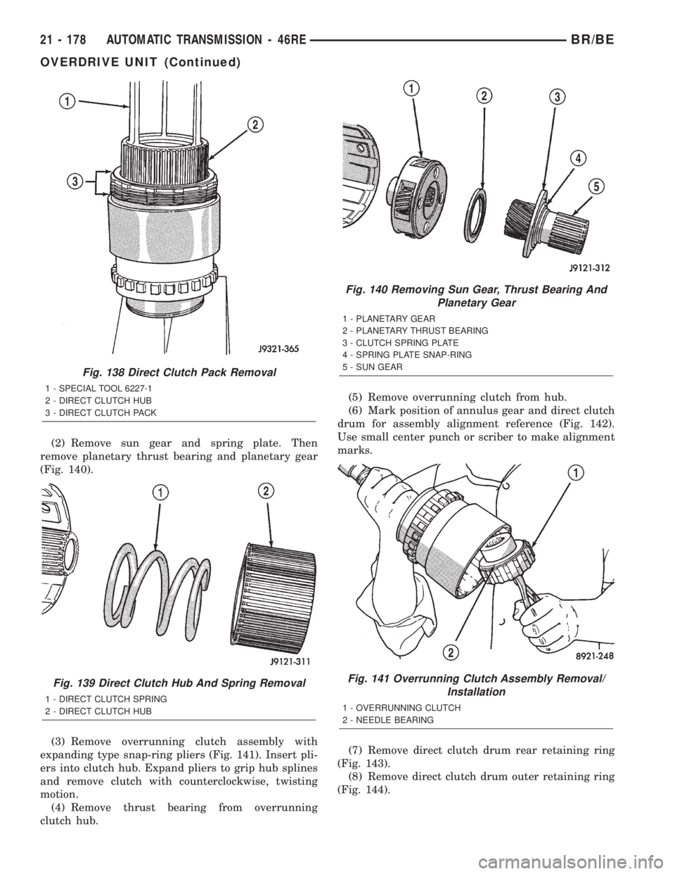
(2) Remove sun gear and spring plate. Then
remove planetary thrust bearing and planetary gear
(Fig. 140).
(3) Remove overrunning clutch assembly with
expanding type snap-ring pliers (Fig. 141). Insert pli-
ers into clutch hub. Expand pliers to grip hub splines
and remove clutch with counterclockwise, twisting
motion.
(4) Remove thrust bearing from overrunning
clutch hub.(5) Remove overrunning clutch from hub.
(6) Mark position of annulus gear and direct clutch
drum for assembly alignment reference (Fig. 142).
Use small center punch or scriber to make alignment
marks.
(7) Remove direct clutch drum rear retaining ring
(Fig. 143).
(8) Remove direct clutch drum outer retaining ring
(Fig. 144).
Fig. 138 Direct Clutch Pack Removal
1 - SPECIAL TOOL 6227-1
2 - DIRECT CLUTCH HUB
3 - DIRECT CLUTCH PACK
Fig. 139 Direct Clutch Hub And Spring Removal
1 - DIRECT CLUTCH SPRING
2 - DIRECT CLUTCH HUB
Fig. 140 Removing Sun Gear, Thrust Bearing And
Planetary Gear
1 - PLANETARY GEAR
2 - PLANETARY THRUST BEARING
3 - CLUTCH SPRING PLATE
4 - SPRING PLATE SNAP-RING
5 - SUN GEAR
Fig. 141 Overrunning Clutch Assembly Removal/
Installation
1 - OVERRUNNING CLUTCH
2 - NEEDLE BEARING
21 - 178 AUTOMATIC TRANSMISSION - 46REBR/BE
OVERDRIVE UNIT (Continued)