2002 DODGE RAM wheel torque
[x] Cancel search: wheel torquePage 1015 of 2255
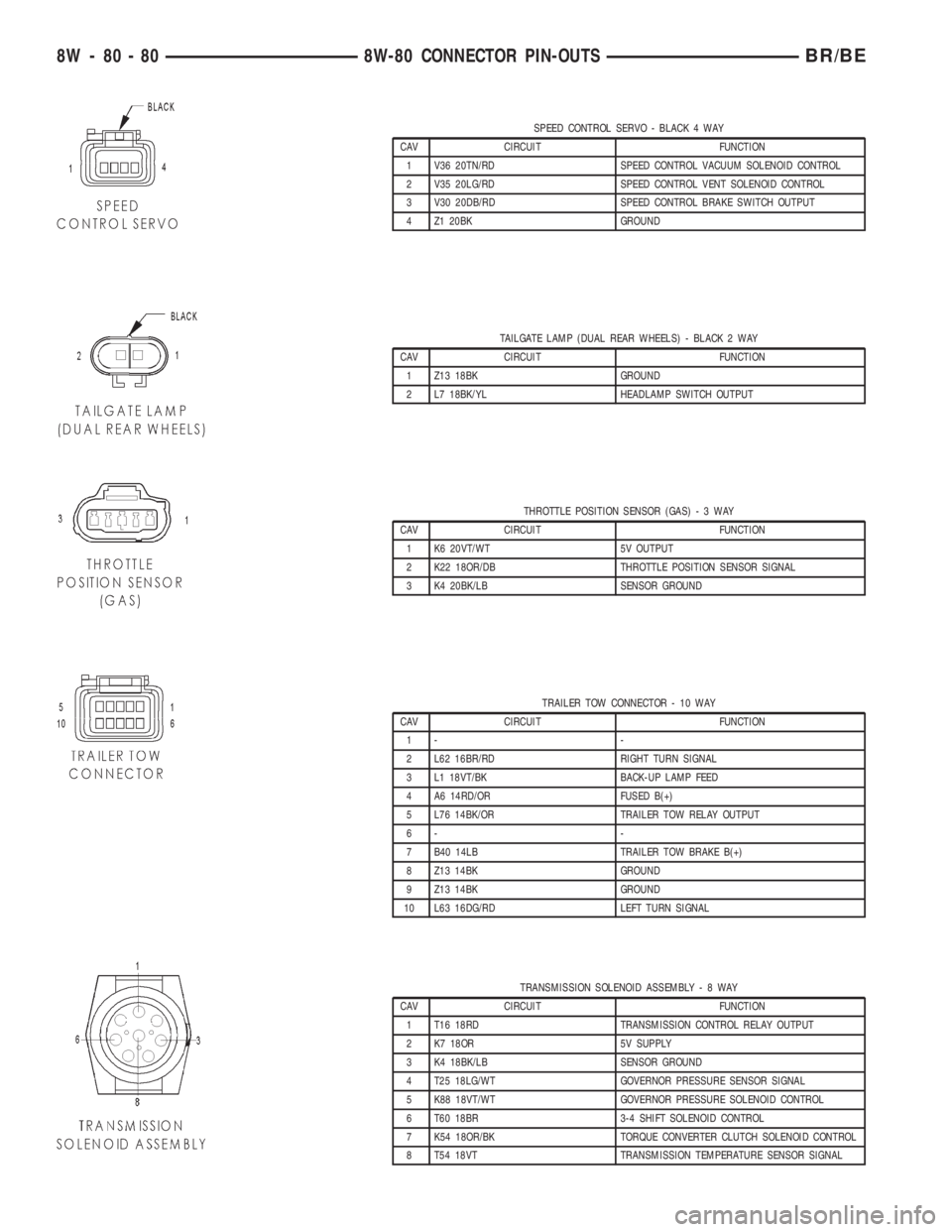
SPEED CONTROL SERVO - BLACK 4 WAY
CAV CIRCUIT FUNCTION
1 V36 20TN/RD SPEED CONTROL VACUUM SOLENOID CONTROL
2 V35 20LG/RD SPEED CONTROL VENT SOLENOID CONTROL
3 V30 20DB/RD SPEED CONTROL BRAKE SWITCH OUTPUT
4 Z1 20BK GROUND
TAILGATE LAMP (DUAL REAR WHEELS) - BLACK 2 WAY
CAV CIRCUIT FUNCTION
1 Z13 18BK GROUND
2 L7 18BK/YL HEADLAMP SWITCH OUTPUT
THROTTLE POSITION SENSOR (GAS)-3WAY
CAV CIRCUIT FUNCTION
1 K6 20VT/WT 5V OUTPUT
2 K22 18OR/DB THROTTLE POSITION SENSOR SIGNAL
3 K4 20BK/LB SENSOR GROUND
TRAILER TOW CONNECTOR - 10 WAY
CAV CIRCUIT FUNCTION
1- -
2 L62 16BR/RD RIGHT TURN SIGNAL
3 L1 18VT/BK BACK-UP LAMP FEED
4 A6 14RD/OR FUSED B(+)
5 L76 14BK/OR TRAILER TOW RELAY OUTPUT
6- -
7 B40 14LB TRAILER TOW BRAKE B(+)
8 Z13 14BK GROUND
9 Z13 14BK GROUND
10 L63 16DG/RD LEFT TURN SIGNAL
TRANSMISSION SOLENOID ASSEMBLY-8WAY
CAV CIRCUIT FUNCTION
1 T16 18RD TRANSMISSION CONTROL RELAY OUTPUT
2 K7 18OR 5V SUPPLY
3 K4 18BK/LB SENSOR GROUND
4 T25 18LG/WT GOVERNOR PRESSURE SENSOR SIGNAL
5 K88 18VT/WT GOVERNOR PRESSURE SOLENOID CONTROL
6 T60 18BR 3-4 SHIFT SOLENOID CONTROL
7 K54 18OR/BK TORQUE CONVERTER CLUTCH SOLENOID CONTROL
8 T54 18VT TRANSMISSION TEMPERATURE SENSOR SIGNAL
8W - 80 - 80 8W-80 CONNECTOR PIN-OUTSBR/BE
Page 1082 of 2255
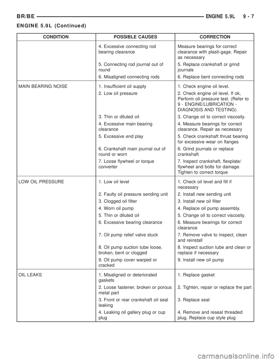
CONDITION POSSIBLE CAUSES CORRECTION
4. Excessive connecting rod
bearing clearanceMeasure bearings for correct
clearance with plasti-gage. Repair
as necessary
5. Connecting rod journal out of
round5. Replace crankshaft or grind
journals
6. Misaligned connecting rods 6. Replace bent connecting rods
MAIN BEARING NOISE 1. Insufficient oil supply 1. Check engine oil level.
2. Low oil pressure 2. Check engine oil level. If ok,
Perform oil pressure test. (Refer to
9 - ENGINE/LUBRICATION -
DIAGNOSIS AND TESTING)
3. Thin or diluted oil 3. Change oil to correct viscosity.
4. Excessive main bearing
clearance4. Measure bearings for correct
clearance. Repair as necessary
5. Excessive end play 5. Check crankshaft thrust bearing
for excessive wear on flanges
6. Crankshaft main journal out of
round or worn6. Grind journals or replace
crankshaft
7. Loose flywheel or torque
converter7. Inspect crankshaft, flexplate/
flywheel and bolts for damage.
Tighten to correct torque
LOW OIL PRESSURE 1. Low oil level 1. Check oil level and fill if
necessary
2. Faulty oil pressure sending unit 2. Install new sending unit
3. Clogged oil filter 3. Install new oil filter
4. Worn oil pump 4. Replace oil pump assembly.
5. Thin or diluted oil 5. Change oil to correct viscosity.
6. Excessive bearing clearance 6. Measure bearings for correct
clearance
7. Oil pump relief valve stuck 7. Remove valve to inspect, clean
and reinstall
8. Oil pump suction tube loose,
broken, bent or clogged8. Inspect suction tube and clean or
replace if necessary
9. Oil pump cover warped or
cracked9. Install new oil pump
OIL LEAKS 1. Misaligned or deteriorated
gaskets1. Replace gasket
2. Loose fastener, broken or porous
metal part2. Tighten, repair or replace the part
3. Front or rear crankshaft oil seal
leaking3. Replace seal
4. Leaking oil gallery plug or cup
plug4. Remove and reseal threaded
plug. Replace cup style plug
BR/BEENGINE 5.9L 9 - 7
ENGINE 5.9L (Continued)
Page 1092 of 2255
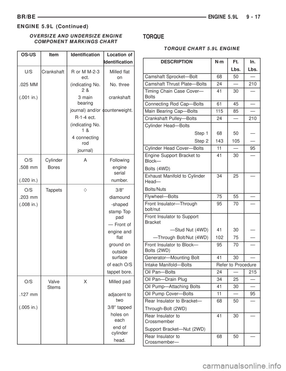
OVERSIZE AND UNDERSIZE ENGINE
COMPONENT MARKINGS CHART
OS-US Item Identification Location of
Identification
U/S Crankshaft R or M M-2-3
ect.Milled flat
on
.025 MM (indicating No.
2&No. three
(.001 in.) 3 main
bearingcrankshaft
journal) and/or counterweight.
R-1-4 ect.
(indicating No.
1&
4 connecting
rod
journal)
O/S Cylinder A Following
.508 mm Bores engine
serial
(.020 in.) number.
O/S TappetsL3/89
.203 mm diamound
(.008 in.) -shaped
stamp Top
pad
Ð Front of
engine and
flat
ground on
outside
surface
of each O/S
tappet bore.
O/S Valve
StemsX Milled pad
.127 mm adjacent to
two
(.005 in.) 3/89tapped
holes on
each
end of
cylinder
head.
TORQUE
TORQUE CHART 5.9L ENGINE
DESCRIPTION N´m Ft. In.
Lbs. Lbs.
Camshaft SprocketÐBolt 68 50 Ð
Camshaft Thrust PlateÐBolts 24 Ð 210
Timing Chain Case CoverÐ
Bolts41 30 Ð
Connecting Rod CapÐBolts 61 45 Ð
Main Bearing CapÐBolts 115 85 Ð
Crankshaft PulleyÐBolts 24 Ð 210
Cylinder HeadÐBolts
Step 1 68 50 Ð
Step 2 143 105 Ð
Cylinder Head CoverÐBolts 11 Ð 95
Engine Support Bracket to
BlockÐ41 30 Ð
Bolts (4WD)
Exhaust Manifold to Cylinder
HeadÐ34 25 Ð
Bolts/Nuts
FlywheelÐBolts 75 55 Ð
Front InsulatorÐThrough
bolt/nut95 70 Ð
Front Insulator to Support
Bracket
ÐStud Nut (4WD) 41 30 Ð
ÐThrough Bolt/Nut (4WD) 102 75 Ð
Front Insulator to BlockÐ
Bolts (2WD)95 70 Ð
GeneratorÐMounting Bolt 41 30 Ð
Intake ManifoldÐBolts Refer to Procedure
Oil PanÐBolts 24 Ð 215
Oil PanÐDrain Plug 34 25 Ð
Oil PumpÐAttaching Bolts 41 30 Ð
Oil Pump CoverÐBolts 11 Ð 95
Rear Insulator to BracketÐ 68 50 Ð
Through-Bolt (2WD)
Rear Insulator to
Crossmember41 30 Ð
Support BracketÐNut (2WD)
Rear Insulator to
CrossmemberÐ68 50 Ð
BR/BEENGINE 5.9L 9 - 17
ENGINE 5.9L (Continued)
Page 1104 of 2255
INSTALLATIONÐCAMSHAFT
(1) Lubricate camshaft lobes and camshaft bearing
journals and insert the camshaft to within 51 mm (2
inches) of its final position in cylinder block.
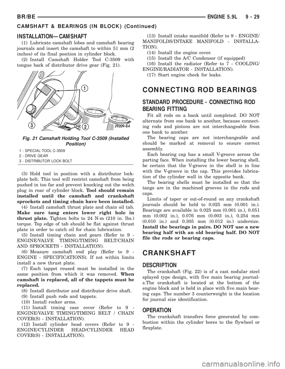
(2) Install Camshaft Holder Tool C-3509 with
tongue back of distributor drive gear (Fig. 21).
(3) Hold tool in position with a distributor lock-
plate bolt. This tool will restrict camshaft from being
pushed in too far and prevent knocking out the welch
plug in rear of cylinder block.Tool should remain
installed until the camshaft and crankshaft
sprockets and timing chain have been installed.
(4) Install camshaft thrust plate and chain oil tab.
Make sure tang enters lower right hole in
thrust plate.Tighten bolts to 24 N´m (210 in. lbs.)
torque. Top edge of tab should be flat against thrust
plate in order to catch oil for chain lubrication.
(5) Install timing chain and gears (Refer to 9 -
ENGINE/VALVE TIMING/TIMING BELT/CHAIN
AND SPROCKETS - INSTALLATION).
(6) Measure camshaft end play (Refer to 9 -
ENGINE - SPECIFICATIONS). If not within limits
install a new thrust plate.
(7) Each tappet reused must be installed in the
same position from which it was removed.When
camshaft is replaced, all of the tappets must be
replaced.
(8) Install distributor and distributor drive shaft.
(9) Install push rods and tappets.
(10) Install rocker arms.
(11) Install timing case cover (Refer to 9 -
ENGINE/VALVE TIMING/TIMING BELT / CHAIN
COVER(S) - INSTALLATION).
(12) Install cylinder head covers (Refer to 9 -
ENGINE/CYLINDER HEAD/CYLINDER HEAD
COVER(S) - INSTALLATION).(13) Install intake manifold (Refer to 9 - ENGINE/
MANIFOLDS/INTAKE MANIFOLD - INSTALLA-
TION).
(14) Install the engine cover.
(15) Install the A/C Condenser (if equipped)
(16) Install the radiator (Refer to 7 - COOLING/
ENGINE/RADIATOR - INSTALLATION).
(17) Start engine check for leaks.
CONNECTING ROD BEARINGS
STANDARD PROCEDURE - CONNECTING ROD
BEARING FITTING
Fit all rods on a bank until completed. DO NOT
alternate from one bank to another, because connect-
ing rods and pistons are not interchangeable from
one bank to another.
The bearing caps are not interchangeable and
should be marked at removal to ensure correct
assembly.
Each bearing cap has a small V-groove across the
parting face. When installing the lower bearing shell,
be certain that the V-groove in the shell is in line
with the V-groove in the cap. This provides lubrica-
tion of the cylinder wall in the opposite bank.
The bearing shells must be installed so that the
tangs are in the machined grooves in the rods and
caps.
Limits of taper or out-of-round on any crankshaft
journals should be held to 0.025 mm (0.001 in.).
Bearings are available in 0.025 mm (0.001 in.), 0.051
mm (0.002 in.), 0.076 mm (0.003 in.), 0.254 mm
(0.010 in.) and 0.305 mm (0.012 in.) undersize.
Install the bearings in pairs. DO NOT use a new
bearing half with an old bearing half. DO NOT
file the rods or bearing caps.
CRANKSHAFT
DESCRIPTION
The crankshaft (Fig. 22) is of a cast nodular steel
splayed type design, with five main bearing journal-
s.The crankshaft is located at the bottom of the
engine block and is held in place with five main bear-
ing caps. The number 3 counterweight is the location
for journal size identification.
OPERATION
The crankshaft transfers force generated by com-
bustion within the cylinder bores to the flywheel or
flexplate.
Fig. 21 Camshaft Holding Tool C-3509 (Installed
Position)
1 - SPECIAL TOOL C-3509
2 - DRIVE GEAR
3 - DISTRIBUTOR LOCK BOLT
BR/BEENGINE 5.9L 9 - 29
CAMSHAFT & BEARINGS (IN BLOCK) (Continued)
Page 1137 of 2255
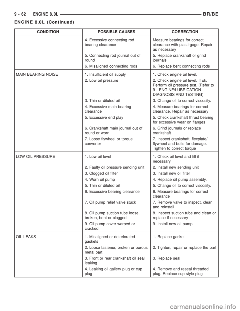
CONDITION POSSIBLE CAUSES CORRECTION
4. Excessive connecting rod
bearing clearanceMeasure bearings for correct
clearance with plasti-gage. Repair
as necessary
5. Connecting rod journal out of
round5. Replace crankshaft or grind
journals
6. Misaligned connecting rods 6. Replace bent connecting rods
MAIN BEARING NOISE 1. Insufficient oil supply 1. Check engine oil level.
2. Low oil pressure 2. Check engine oil level. If ok,
Perform oil pressure test. (Refer to
9 - ENGINE/LUBRICATION -
DIAGNOSIS AND TESTING)
3. Thin or diluted oil 3. Change oil to correct viscosity.
4. Excessive main bearing
clearance4. Measure bearings for correct
clearance. Repair as necessary
5. Excessive end play 5. Check crankshaft thrust bearing
for excessive wear on flanges
6. Crankshaft main journal out of
round or worn6. Grind journals or replace
crankshaft
7. Loose flywheel or torque
converter7. Inspect crankshaft, flexplate/
flywheel and bolts for damage.
Tighten to correct torque
LOW OIL PRESSURE 1. Low oil level 1. Check oil level and fill if
necessary
2. Faulty oil pressure sending unit 2. Install new sending unit
3. Clogged oil filter 3. Install new oil filter
4. Worn oil pump 4. Replace oil pump assembly.
5. Thin or diluted oil 5. Change oil to correct viscosity.
6. Excessive bearing clearance 6. Measure bearings for correct
clearance
7. Oil pump relief valve stuck 7. Remove valve to inspect, clean
and reinstall
8. Oil pump suction tube loose,
broken, bent or clogged8. Inspect suction tube and clean or
replace if necessary
9. Oil pump cover warped or
cracked9. Install new oil pump
OIL LEAKS 1. Misaligned or deteriorated
gaskets1. Replace gasket
2. Loose fastener, broken or porous
metal part2. Tighten, repair or replace the part
3. Front or rear crankshaft oil seal
leaking3. Replace seal
4. Leaking oil gallery plug or cup
plug4. Remove and reseal threaded
plug. Replace cup style plug
9 - 62 ENGINE 8.0LBR/BE
ENGINE 8.0L (Continued)
Page 1236 of 2255
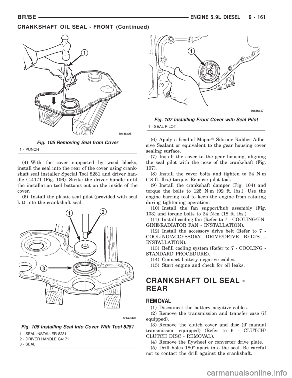
(4) With the cover supported by wood blocks,
install the seal into the rear of the cover using crank-
shaft seal installer Special Tool 8281 and driver han-
dle C-4171 (Fig. 106). Strike the driver handle until
the installation tool bottoms out on the inside of the
cover.
(5) Install the plastic seal pilot (provided with seal
kit) into the crankshaft seal.(6) Apply a bead of MopartSilicone Rubber Adhe-
sive Sealant or equivalent to the gear housing cover
sealing surface.
(7) Install the cover to the gear housing, aligning
the seal pilot with the nose of the crankshaft (Fig.
107).
(8) Install the cover bolts and tighten to 24 N´m
(18 ft. lbs.) torque. Remove pilot tool.
(9) Install the crankshaft damper (Fig. 104) and
torque the bolts to 125 N´m (92 ft. lbs.). Use the
engine barring tool to keep the engine from rotating
during tightening operation.
(10) Install the fan support/hub assembly (Fig.
103) and torque bolts to 24 N´m (18 ft. lbs.).
(11) Install cooling fan (Refer to 7 - COOLING/EN-
GINE/RADIATOR FAN - INSTALLATION).
(12) Install the accessory drive belt (Refer to 7 -
COOLING/ACCESSORY DRIVE/DRIVE BELTS -
INSTALLATION).
(13) Refill cooling system (Refer to 7 - COOLING -
STANDARD PROCEDURE).
(14) Connect battery negative cables.
(15) Start engine and check for oil leaks.
CRANKSHAFT OIL SEAL -
REAR
REMOVAL
(1) Disconnect the battery negative cables.
(2) Remove the transmission and transfer case (if
equipped).
(3) Remove the clutch cover and disc (if manual
transmission equipped) (Refer to 6 - CLUTCH/
CLUTCH DISC - REMOVAL).
(4) Remove the flywheel or converter drive plate.
(5) Drill holes 180É apart into the seal. Be careful
not to contact the drill against the crankshaft.
Fig. 105 Removing Seal from Cover
1 - PUNCH
Fig. 106 Installing Seal Into Cover With Tool 8281
1 - SEAL INSTALLER 8281
2 - DRIVER HANDLE C4171
3 - SEAL
Fig. 107 Installing Front Cover with Seal Pilot
1 - SEAL PILOT
BR/BEENGINE 5.9L DIESEL 9 - 161
CRANKSHAFT OIL SEAL - FRONT (Continued)
Page 1237 of 2255
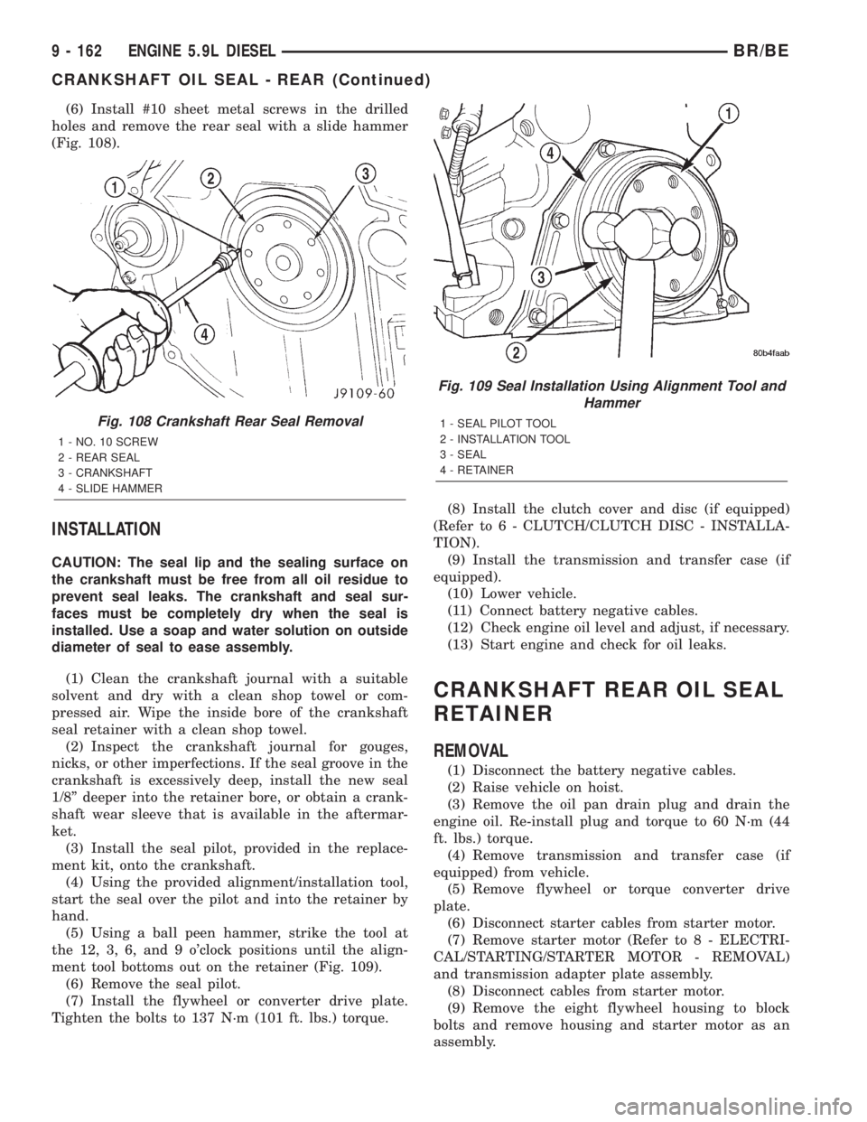
(6) Install #10 sheet metal screws in the drilled
holes and remove the rear seal with a slide hammer
(Fig. 108).
INSTALLATION
CAUTION: The seal lip and the sealing surface on
the crankshaft must be free from all oil residue to
prevent seal leaks. The crankshaft and seal sur-
faces must be completely dry when the seal is
installed. Use a soap and water solution on outside
diameter of seal to ease assembly.
(1) Clean the crankshaft journal with a suitable
solvent and dry with a clean shop towel or com-
pressed air. Wipe the inside bore of the crankshaft
seal retainer with a clean shop towel.
(2) Inspect the crankshaft journal for gouges,
nicks, or other imperfections. If the seal groove in the
crankshaft is excessively deep, install the new seal
1/8º deeper into the retainer bore, or obtain a crank-
shaft wear sleeve that is available in the aftermar-
ket.
(3) Install the seal pilot, provided in the replace-
ment kit, onto the crankshaft.
(4) Using the provided alignment/installation tool,
start the seal over the pilot and into the retainer by
hand.
(5) Using a ball peen hammer, strike the tool at
the 12, 3, 6, and 9 o'clock positions until the align-
ment tool bottoms out on the retainer (Fig. 109).
(6) Remove the seal pilot.
(7) Install the flywheel or converter drive plate.
Tighten the bolts to 137 N´m (101 ft. lbs.) torque.(8) Install the clutch cover and disc (if equipped)
(Refer to 6 - CLUTCH/CLUTCH DISC - INSTALLA-
TION).
(9) Install the transmission and transfer case (if
equipped).
(10) Lower vehicle.
(11) Connect battery negative cables.
(12) Check engine oil level and adjust, if necessary.
(13) Start engine and check for oil leaks.
CRANKSHAFT REAR OIL SEAL
RETAINER
REMOVAL
(1) Disconnect the battery negative cables.
(2) Raise vehicle on hoist.
(3) Remove the oil pan drain plug and drain the
engine oil. Re-install plug and torque to 60 N´m (44
ft. lbs.) torque.
(4) Remove transmission and transfer case (if
equipped) from vehicle.
(5) Remove flywheel or torque converter drive
plate.
(6) Disconnect starter cables from starter motor.
(7) Remove starter motor (Refer to 8 - ELECTRI-
CAL/STARTING/STARTER MOTOR - REMOVAL)
and transmission adapter plate assembly.
(8) Disconnect cables from starter motor.
(9) Remove the eight flywheel housing to block
bolts and remove housing and starter motor as an
assembly.
Fig. 108 Crankshaft Rear Seal Removal
1 - NO. 10 SCREW
2 - REAR SEAL
3 - CRANKSHAFT
4 - SLIDE HAMMER
Fig. 109 Seal Installation Using Alignment Tool and
Hammer
1 - SEAL PILOT TOOL
2 - INSTALLATION TOOL
3 - SEAL
4 - RETAINER
9 - 162 ENGINE 5.9L DIESELBR/BE
CRANKSHAFT OIL SEAL - REAR (Continued)
Page 1239 of 2255
(8) Install the oil pan, suction tube and gaskets
(Refer to 9 - ENGINE/LUBRICATION/OIL PAN -
INSTALLATION).
(9) Install the flywheel housing and bolts. Tighten
the bolts to 60 N´m (44 ft. lbs.) torque.
(10) Install the starter motor (Refer to 8 - ELEC-
TRICAL/STARTING/STARTER MOTOR - INSTAL-
LATION).
(11) Install the flywheel or converter drive plate.
Tighten bolts to 137 N´m (101 ft. lbs.)
(12) Install the transmission and transfer case (if
equipped).
(13) Lower vehicle.(14) Fill the crankcase with new engine oil.
(15) Connect the battery negative cables.
(16) Start engine and check for oil leaks.
SOLID LIFTERS/TAPPETS
REMOVAL
NOTE: This procedure requires use of Miller Tool
8502 Tappet Replacement Kit, or Cummins Tool Kit
#3822513.
(1) Remove camshaft (Refer to 9 - ENGINE/EN-
GINE BLOCK/CAMSHAFT & BEARINGS (IN
BLOCK) - REMOVAL).
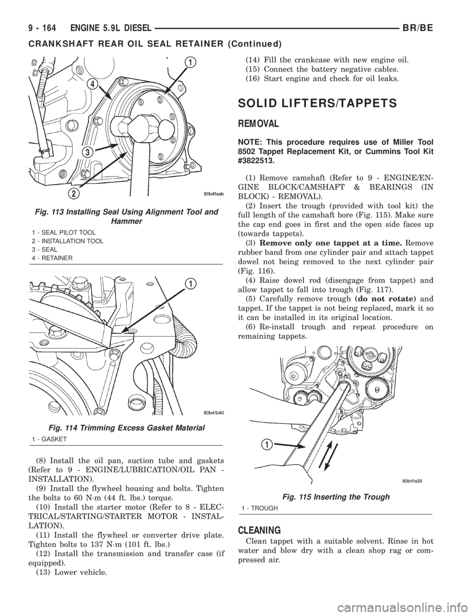
(2) Insert the trough (provided with tool kit) the
full length of the camshaft bore (Fig. 115). Make sure
the cap end goes in first and the open side faces up
(towards tappets).
(3)Remove only one tappet at a time.Remove
rubber band from one cylinder pair and attach tappet
dowel not being removed to the next cylinder pair
(Fig. 116).
(4) Raise dowel rod (disengage from tappet) and
allow tappet to fall into trough (Fig. 117).
(5) Carefully remove trough(do not rotate)and
tappet. If the tappet is not being replaced, mark it so
it can be installed in its original location.
(6) Re-install trough and repeat procedure on
remaining tappets.
CLEANING
Clean tappet with a suitable solvent. Rinse in hot
water and blow dry with a clean shop rag or com-
pressed air.
Fig. 113 Installing Seal Using Alignment Tool and
Hammer
1 - SEAL PILOT TOOL
2 - INSTALLATION TOOL
3 - SEAL
4 - RETAINER
Fig. 114 Trimming Excess Gasket Material
1 - GASKET
Fig. 115 Inserting the Trough
1 - TROUGH
9 - 164 ENGINE 5.9L DIESELBR/BE
CRANKSHAFT REAR OIL SEAL RETAINER (Continued)