2002 DODGE RAM remove seats
[x] Cancel search: remove seatsPage 1583 of 2255
(a) Loosen locknut on each band adjusting screw
4-5 turns.
(b) Tighten both adjusting screws to 8 N´m (72
in. lbs.).
(c) Back off front band adjusting screw 2-7/8
turns.
(d) Back off rear band adjusting screw 2 turns.
(e) Hold each adjusting screw in position and
tighten locknut to 34 N´m (25 ft. lbs.) torque.
(2) Install magnet in oil pan. Magnet seats on
small protrusion at corner of pan.
(3) Position new oil pan gasket on case and install
oil pan. Tighten pan bolts to 13.6 N´m (125 in. lbs.).
(4) Install throttle valve and shift selector levers
on valve body manual lever shaft.
(5) Apply small quantity of dielectric grease to ter-
minal pins of solenoid case connector and neutral
switch.
(6) Fill transmission with recommended fluid.
Refer to Service Procedures section of this group.
INSTALLATION
(1) Check torque converter hub and hub drive
notches for sharp edges burrs, scratches, or nicks.
Polish the hub and notches with 320/400 grit paper
and crocus cloth if necessary. The hub must be
smooth to avoid damaging pump seal at installation.
(2) Lubricate pocket in the rear oil pump seal lip
with transmission fluid.(3) Lubricate converter pilot hub of the crankshaft
with a light coating of MopartHigh Temp Grease.
(4) Align and install converter in oil pump.
(5) Carefully insert converter in oil pump. Then
rotate converter back and forth until fully seated in
pump gears.
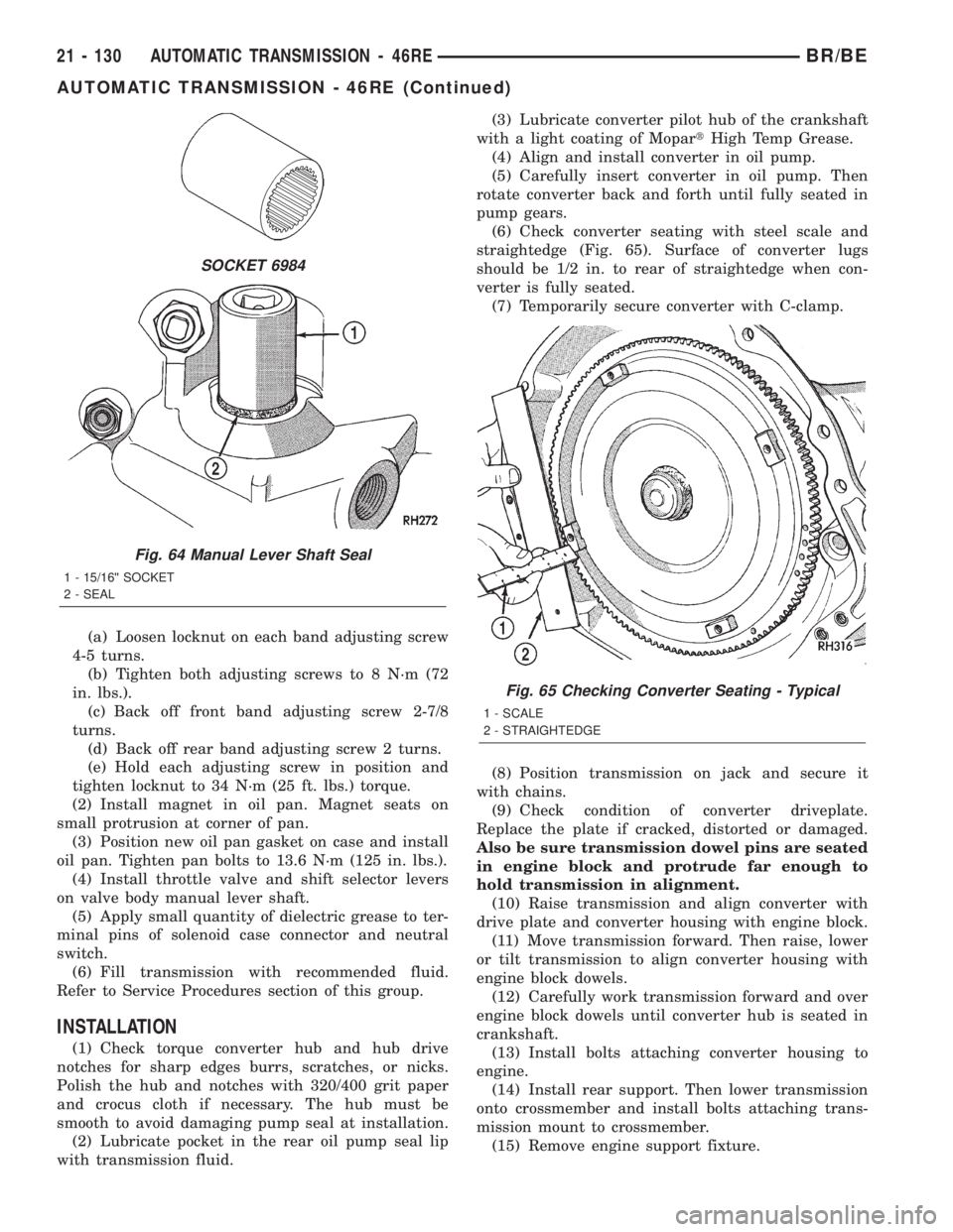
(6) Check converter seating with steel scale and
straightedge (Fig. 65). Surface of converter lugs
should be 1/2 in. to rear of straightedge when con-
verter is fully seated.
(7) Temporarily secure converter with C-clamp.
(8) Position transmission on jack and secure it
with chains.
(9) Check condition of converter driveplate.
Replace the plate if cracked, distorted or damaged.
Also be sure transmission dowel pins are seated
in engine block and protrude far enough to
hold transmission in alignment.
(10) Raise transmission and align converter with
drive plate and converter housing with engine block.
(11) Move transmission forward. Then raise, lower
or tilt transmission to align converter housing with
engine block dowels.
(12) Carefully work transmission forward and over
engine block dowels until converter hub is seated in
crankshaft.
(13) Install bolts attaching converter housing to
engine.
(14) Install rear support. Then lower transmission
onto crossmember and install bolts attaching trans-
mission mount to crossmember.
(15) Remove engine support fixture.
SOCKET 6984
Fig. 64 Manual Lever Shaft Seal
1 - 15/16©© SOCKET
2 - SEAL
Fig. 65 Checking Converter Seating - Typical
1 - SCALE
2 - STRAIGHTEDGE
21 - 130 AUTOMATIC TRANSMISSION - 46REBR/BE
AUTOMATIC TRANSMISSION - 46RE (Continued)
Page 1873 of 2255
CAUTION: Many of the valves and plugs, such as
the throttle valve, shuttle valve plug, 1-2 shift valve
and 1-2 governor plug, are made of coated alumi-
num. Aluminum components are identified by the
dark color of the special coating applied to the sur-
face (or by testing with a magnet). Do not sand alu-
minum valves or plugs under any circumstances.
This practice could damage the special coating
causing the valves/plugs to stick and bind.
Inspect the valves and plugs for scratches, burrs,
nicks, or scores. Minor surface scratches on steel
valves and plugs can be removed with crocus cloth
butdo not round off the edges of the valve or
plug lands.Maintaining sharpness of these edges is
vitally important. The edges prevent foreign matter
from lodging between the valves and plugs and the
bore.
Inspect all the valve and plug bores in the valve
body. Use a penlight to view the bore interiors.
Replace the valve body if any bores are distorted or
scored. Inspect all of the valve body springs. The
springs must be free of distortion, warpage or broken
coils.
Check the two separator plates for distortion or
damage of any kind. Inspect the upper housing,
lower housing, 3-4 accumulator housing, and transfer
plate carefully. Be sure all fluid passages are clean
and clear. Check condition of the upper housing andtransfer plate check balls as well. The check balls
and ball seats must not be worn or damaged.
Trial fit each valve and plug in its bore to check
freedom of operation. When clean and dry, the valves
and plugs should drop freely into the bores.
Valve body bores do not change dimensionally with
use. If the valve body functioned correctly when new,
it will continue to operate properly after cleaning and
inspection. It should not be necessary to replace a
valve body assembly unless it is damaged in han-
dling.
The only serviceable valve body components are
listed below. The remaining valve body components
are serviced only as part of a complete valve body
assembly. Serviceable parts are:
²dual solenoid and harness assembly
²solenoid gasket
²solenoid case connector O-rings and shoulder
bolt
²switch valve and spring
²pressure adjusting screw and bracket assembly
²throttle lever
²manual lever and shaft seal
²throttle lever shaft seal, washer, and E-clip
²fluid filter and screws
²detent ball and spring
²valve body screws
²governor pressure solenoid
²governor pressure sensor and retaining clip
²park lock rod and E-clip
ASSEMBLY
CAUTION: Do not force valves or plugs into place
during reassembly. If the valve body bores, valves
and plugs are free of distortion or burrs, the valve
body components should all slide into place easily.
In addition, do not overtighten the transfer plate
and valve body screws during reassembly. Over-
tightening can distort the housings resulting in
valve sticking, cross leakage and unsatisfactory
operation. Tighten valve body screws to recom-
mended torque only.
LOWER HOUSING
(1) Lubricate valves, springs, and the housing
valve and plug bores with clean transmission fluid
(Fig. 301).
(2) Install 3-4 timing valve spring and valve in
lower housing.
(3) Install 3-4 quick fill valve in lower housing.
(4) Install 3-4 quick fill valve spring and plug in
housing.
(5) Install timing valve end plate. Tighten end
plate screws to 4 N´m (35 in. lbs.) torque.
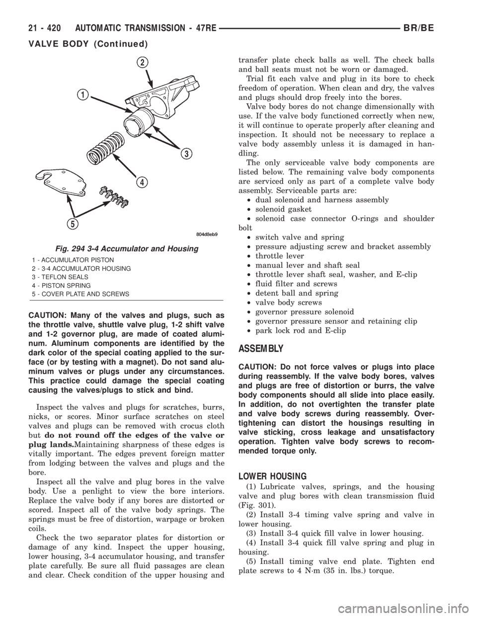
Fig. 294 3-4 Accumulator and Housing
1 - ACCUMULATOR PISTON
2 - 3-4 ACCUMULATOR HOUSING
3 - TEFLON SEALS
4 - PISTON SPRING
5 - COVER PLATE AND SCREWS
21 - 420 AUTOMATIC TRANSMISSION - 47REBR/BE
VALVE BODY (Continued)
Page 1913 of 2255
EXTENSION HOUSING
BUSHING AND SEAL
REMOVAL
(1) Raise and support vehicle.
(2) Remove rear propeller shaft. (Refer to 3 - DIF-
FERENTIAL & DRIVELINE/PROPELLER SHAFT/
PROPELLER SHAFT - REMOVAL)
(3) Using a suitable pry tool or slide-hammer
mounted screw, remove the extension housing seal.
(4) Using Remover 8158, remove bushing from
extension housing.
INSTALLATION
(1) Clean fluid residue from sealing surface and
inspect for defects.
(2) Position replacement bushing in extension
housing with fluid port in bushing aligned with slot
in housing.
(3) Using Installer 8157, drive bushing into hous-
ing until installer seats against case.
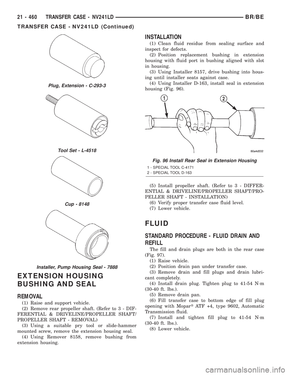
(4) Using Installer D-163, install seal in extension
housing (Fig. 96).
(5) Install propeller shaft. (Refer to 3 - DIFFER-
ENTIAL & DRIVELINE/PROPELLER SHAFT/PRO-
PELLER SHAFT - INSTALLATION)
(6) Verify proper transfer case fluid level.
(7) Lower vehicle.
FLUID
STANDARD PROCEDURE - FLUID DRAIN AND
REFILL
The fill and drain plugs are both in the rear case
(Fig. 97).
(1) Raise vehicle.
(2) Position drain pan under transfer case.
(3) Remove drain and fill plugs and drain lubri-
cant completely.
(4) Install drain plug. Tighten plug to 41-54 N´m
(30-40 ft. lbs.).
(5) Remove drain pan.
(6) Fill transfer case to bottom edge of fill plug
opening with MopartATF +4, type 9602, Automatic
Transmission fluid.
(7) Install and tighten fill plug to 41-54 N´m
(30-40 ft. lbs.).
(8) Lower vehicle.
Plug, Extension - C-293-3
Tool Set - L-4518
Cup - 8148
Installer, Pump Housing Seal - 7888
Fig. 96 Install Rear Seal in Extension Housing
1 - SPECIAL TOOL C-4171
2 - SPECIAL TOOL D-163
21 - 460 TRANSFER CASE - NV241LDBR/BE
TRANSFER CASE - NV241LD (Continued)
Page 1950 of 2255
EXTENSION HOUSING
BUSHING AND SEAL
REMOVAL
(1) Raise and support vehicle.
(2) Remove rear propeller shaft. (Refer to 3 - DIF-
FERENTIAL & DRIVELINE/PROPELLER SHAFT/
PROPELLER SHAFT - REMOVAL)
(3) Using a suitable pry tool or slide-hammer
mounted screw, remove the extension housing seal.
(4) Using Remover 8155, remove bushing from
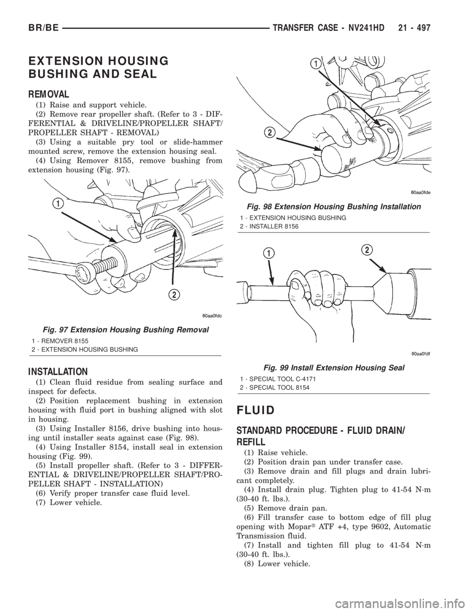
extension housing (Fig. 97).
INSTALLATION
(1) Clean fluid residue from sealing surface and
inspect for defects.
(2) Position replacement bushing in extension
housing with fluid port in bushing aligned with slot
in housing.
(3) Using Installer 8156, drive bushing into hous-
ing until installer seats against case (Fig. 98).
(4) Using Installer 8154, install seal in extension
housing (Fig. 99).
(5) Install propeller shaft. (Refer to 3 - DIFFER-
ENTIAL & DRIVELINE/PROPELLER SHAFT/PRO-
PELLER SHAFT - INSTALLATION)
(6) Verify proper transfer case fluid level.
(7) Lower vehicle.
FLUID
STANDARD PROCEDURE - FLUID DRAIN/
REFILL
(1) Raise vehicle.
(2) Position drain pan under transfer case.
(3) Remove drain and fill plugs and drain lubri-
cant completely.
(4) Install drain plug. Tighten plug to 41-54 N´m
(30-40 ft. lbs.).
(5) Remove drain pan.
(6) Fill transfer case to bottom edge of fill plug
opening with MopartATF +4, type 9602, Automatic
Transmission fluid.
(7) Install and tighten fill plug to 41-54 N´m
(30-40 ft. lbs.).
(8) Lower vehicle.
Fig. 97 Extension Housing Bushing Removal
1 - REMOVER 8155
2 - EXTENSION HOUSING BUSHING
Fig. 98 Extension Housing Bushing Installation
1 - EXTENSION HOUSING BUSHING
2 - INSTALLER 8156
Fig. 99 Install Extension Housing Seal
1 - SPECIAL TOOL C-4171
2 - SPECIAL TOOL 8154
BR/BETRANSFER CASE - NV241HD 21 - 497
Page 1968 of 2255
BODY
TABLE OF CONTENTS
page page
BODY
WARNING
SAFETY PRECAUTIONS AND WARNINGS . . . 1
DIAGNOSIS AND TESTING
DIAGNOSIS AND TESTING - WATER LEAKS . 2
DIAGNOSIS AND TESTING - WIND NOISE . . . 3
SPECIFICATIONS
WELD LOCATIONS.....................4
STRUCTURAL ADHESIVE LOCATIONS.....44
BODY SEALER LOCATIONS.............47
BODY GAP AND FLUSH MEASUREMENTS . . 56
BODY OPENING DIMENSIONS...........60TORQUE SPECIFICATIONS.............61
DECKLID/HATCH/LIFTGATE/TAILGATE.......63
DOOR - FRONT.........................68
DOOR - CARGO.........................77
EXTERIOR.............................86
HOOD................................100
INSTRUMENT PANEL SYSTEM............105
INTERIOR.............................118
PAINT................................129
SEATS...............................131
STATIONARY GLASS....................145
WEATHERSTRIP/SEALS..................151
BODY
WARNING
SAFETY PRECAUTIONS AND WARNINGS
WARNING: USE AN OSHA APPROVED BREATHING
FILTER WHEN SPRAYING PAINT OR SOLVENTS IN
A CONFINED AREA. PERSONAL INJURY CAN
RESULT.
²AVOID PROLONGED SKIN CONTACT WITH
PETROLEUM OR ALCOHOL ± BASED CLEANING
SOLVENTS. PERSONAL INJURY CAN RESULT.
²DO NOT STAND UNDER A HOISTED VEHICLE
THAT IS NOT PROPERLY SUPPORTED ON SAFETY
STANDS. PERSONAL INJURY CAN RESULT.CAUTION: When holes must be drilled or punched
in an inner body panel, verify depth of space to the
outer body panel, electrical wiring, or other compo-
nents. Damage to vehicle can result.
²Do not weld exterior panels unless combustible
material on the interior of vehicle is removed from
the repair area. Fire or hazardous conditions, can
result.
²Always have a fire extinguisher ready for use
when welding.
²Disconnect the negative (-) cable clamp from
the battery when servicing electrical components
that are live when the ignition is OFF. Damage to
electrical system can result.
²Do not use abrasive chemicals or compounds
on painted surfaces. Damage to finish can result.
²Do not use harsh alkaline based cleaning sol-
vents on painted or upholstered surfaces. Damage
to finish or color can result.
²Do not hammer or pound on plastic trim panel
when servicing interior trim. Plastic panels can
break.
BR/BEBODY 23 - 1
Page 2090 of 2255
(4) Install the screws attaching the console to
mounting brackets.
(5) Install the transmission shifter boot, (Refer to
23 - BODY/INTERIOR/SHIFT BOOT - INSTALLA-
TION).
(6) Install the transfer case shifter boot, if
equipped. (Refer to 23 - BODY/INTERIOR/SHIFT
BOOT - INSTALLATION).
(7) Install cup holder in console, if equipped.
CARPETS AND FLOOR MATS
REMOVAL
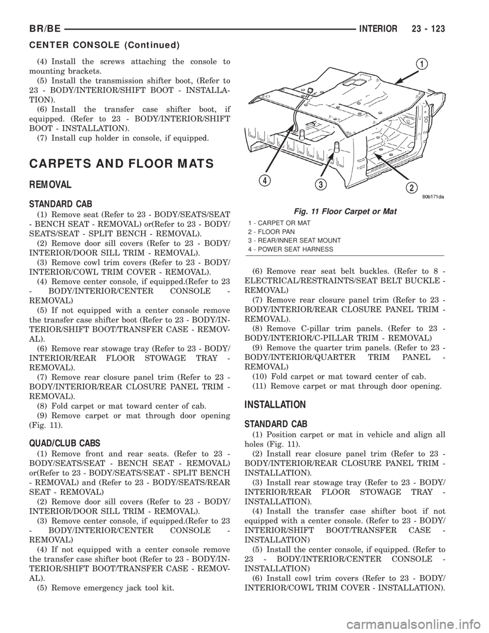
STANDARD CAB
(1) Remove seat (Refer to 23 - BODY/SEATS/SEAT
- BENCH SEAT - REMOVAL) or(Refer to 23 - BODY/
SEATS/SEAT - SPLIT BENCH - REMOVAL).
(2) Remove door sill covers (Refer to 23 - BODY/
INTERIOR/DOOR SILL TRIM - REMOVAL).
(3) Remove cowl trim covers (Refer to 23 - BODY/
INTERIOR/COWL TRIM COVER - REMOVAL).
(4) Remove center console, if equipped.(Refer to 23
- BODY/INTERIOR/CENTER CONSOLE -
REMOVAL)
(5) If not equipped with a center console remove
the transfer case shifter boot (Refer to 23 - BODY/IN-
TERIOR/SHIFT BOOT/TRANSFER CASE - REMOV-
AL).
(6) Remove rear stowage tray (Refer to 23 - BODY/
INTERIOR/REAR FLOOR STOWAGE TRAY -
REMOVAL).
(7) Remove rear closure panel trim (Refer to 23 -
BODY/INTERIOR/REAR CLOSURE PANEL TRIM -
REMOVAL).
(8) Fold carpet or mat toward center of cab.
(9) Remove carpet or mat through door opening
(Fig. 11).
QUAD/CLUB CABS
(1) Remove front and rear seats. (Refer to 23 -
BODY/SEATS/SEAT - BENCH SEAT - REMOVAL)
or(Refer to 23 - BODY/SEATS/SEAT - SPLIT BENCH
- REMOVAL) and (Refer to 23 - BODY/SEATS/REAR
SEAT - REMOVAL)
(2) Remove door sill covers (Refer to 23 - BODY/
INTERIOR/DOOR SILL TRIM - REMOVAL).
(3) Remove center console, if equipped.(Refer to 23
- BODY/INTERIOR/CENTER CONSOLE -
REMOVAL)
(4) If not equipped with a center console remove
the transfer case shifter boot (Refer to 23 - BODY/IN-
TERIOR/SHIFT BOOT/TRANSFER CASE - REMOV-
AL).
(5) Remove emergency jack tool kit.(6) Remove rear seat belt buckles. (Refer to 8 -
ELECTRICAL/RESTRAINTS/SEAT BELT BUCKLE -
REMOVAL)
(7) Remove rear closure panel trim (Refer to 23 -
BODY/INTERIOR/REAR CLOSURE PANEL TRIM -
REMOVAL).
(8) Remove C-pillar trim panels. (Refer to 23 -
BODY/INTERIOR/C-PILLAR TRIM - REMOVAL)
(9) Remove the quarter trim panels. (Refer to 23 -
BODY/INTERIOR/QUARTER TRIM PANEL -
REMOVAL)
(10) Fold carpet or mat toward center of cab.
(11) Remove carpet or mat through door opening.
INSTALLATION
STANDARD CAB
(1) Position carpet or mat in vehicle and align all
holes (Fig. 11).
(2) Install rear closure panel trim (Refer to 23 -
BODY/INTERIOR/REAR CLOSURE PANEL TRIM -
INSTALLATION).
(3) Install rear stowage tray (Refer to 23 - BODY/
INTERIOR/REAR FLOOR STOWAGE TRAY -
INSTALLATION).
(4) Install the transfer case shifter boot if not
equipped with a center console. (Refer to 23 - BODY/
INTERIOR/SHIFT BOOT/TRANSFER CASE -
INSTALLATION)
(5) Install the center console, if equipped. (Refer to
23 - BODY/INTERIOR/CENTER CONSOLE -
INSTALLATION)
(6) Install cowl trim covers (Refer to 23 - BODY/
INTERIOR/COWL TRIM COVER - INSTALLATION).
Fig. 11 Floor Carpet or Mat
1 - CARPET OR MAT
2 - FLOOR PAN
3 - REAR/INNER SEAT MOUNT
4 - POWER SEAT HARNESS
BR/BEINTERIOR 23 - 123
CENTER CONSOLE (Continued)
Page 2091 of 2255
(7) Install door sill covers (Refer to 23 - BODY/IN-
TERIOR/DOOR SILL TRIM - INSTALLATION).
(8) Install seat, (Refer to 23 - BODY/SEATS/SEAT
- INSTALLATION) or (Refer to 23 - BODY/SEATS/
SEAT/SPLIT BENCH - INSTALLATION).
QUAD/CLUB CABS
(1) Position carpet or mat in vehicle.
(2) Install quarter trim panels. (Refer to 23 -
BODY/INTERIOR/QUARTER TRIM PANEL -
INSTALLATION)
(3) Install rear seat belt buckles.
(4) Install the C-pillar trim panels, if equipped.
(Refer to 23 - BODY/INTERIOR/C-PILLAR TRIM -
INSTALLATION)
(5) Install rear closure panel trim (Refer to 23 -
BODY/INTERIOR/REAR CLOSURE PANEL TRIM -
INSTALLATION).
(6) Install the rear seat belt buckles. (Refer to 8 -
ELECTRICAL/RESTRAINTS/SEAT BELT BUCKLE -
INSTALLATION)
(7) Install emergency jack tool kit.
(8) Install the transfer case shifter boot if not
equipped with a center console. (Refer to 23 - BODY/
INTERIOR/SHIFT BOOT/TRANSFER CASE -
INSTALLATION)
(9) Install the center console, if equipped. (Refer to
23 - BODY/INTERIOR/CENTER CONSOLE -
INSTALLATION)
(10) Install floor shift boot, if equipped.
(11) Install cowl trim covers (Refer to 23 - BODY/
INTERIOR/COWL TRIM COVER - INSTALLATION).
(12) Install door sill covers (Refer to 23 - BODY/
INTERIOR/DOOR SILL TRIM - INSTALLATION).
(13) Install front and rear seats. (Refer to 23 -
BODY/SEATS/SEAT - BENCH SEAT - INSTALLA-
TION) or (Refer to 23 - BODY/SEATS/SEAT - SPLIT
BENCH - INSTALLATION) and (Refer to 23 - BODY/
SEATS/REAR SEAT - INSTALLATION)
ASSIST HANDLE
REMOVAL
(1) Disengage tabs attaching assist handle end
covers to assist handle.
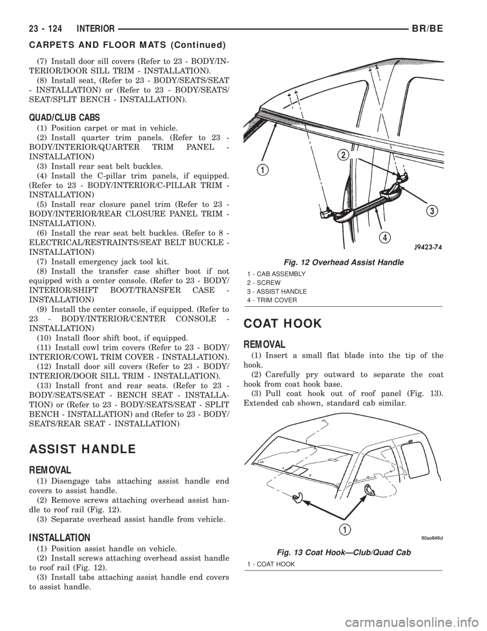
(2) Remove screws attaching overhead assist han-
dle to roof rail (Fig. 12).
(3) Separate overhead assist handle from vehicle.
INSTALLATION
(1) Position assist handle on vehicle.
(2) Install screws attaching overhead assist handle
to roof rail (Fig. 12).
(3) Install tabs attaching assist handle end covers
to assist handle.
COAT HOOK
REMOVAL
(1) Insert a small flat blade into the tip of the
hook.
(2) Carefully pry outward to separate the coat
hook from coat hook base.
(3) Pull coat hook out of roof panel (Fig. 13).
Extended cab shown, standard cab similar.
Fig. 12 Overhead Assist Handle
1 - CAB ASSEMBLY
2 - SCREW
3 - ASSIST HANDLE
4 - TRIM COVER
Fig. 13 Coat HookÐClub/Quad Cab
1 - COAT HOOK
23 - 124 INTERIORBR/BE
CARPETS AND FLOOR MATS (Continued)
Page 2095 of 2255
QUARTER TRIM PANEL
REMOVAL
(1) Remove rear seat. (Refer to 23 - BODY/SEATS/
REAR SEAT - REMOVAL)
(2) Remove door sill cover as necessary to clear
quarter trim.
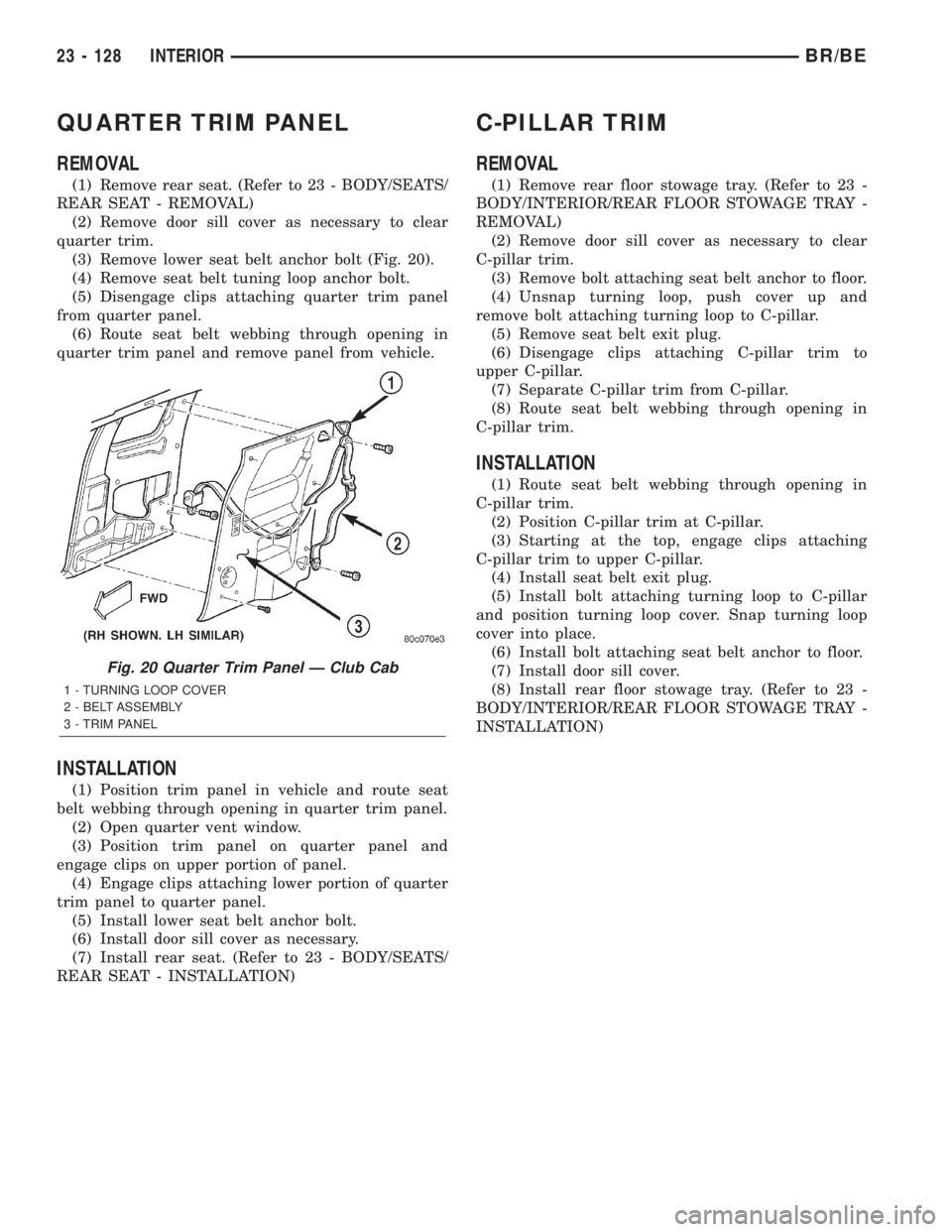
(3) Remove lower seat belt anchor bolt (Fig. 20).
(4) Remove seat belt tuning loop anchor bolt.
(5) Disengage clips attaching quarter trim panel
from quarter panel.
(6) Route seat belt webbing through opening in
quarter trim panel and remove panel from vehicle.
INSTALLATION
(1) Position trim panel in vehicle and route seat
belt webbing through opening in quarter trim panel.
(2) Open quarter vent window.
(3) Position trim panel on quarter panel and
engage clips on upper portion of panel.
(4) Engage clips attaching lower portion of quarter
trim panel to quarter panel.
(5) Install lower seat belt anchor bolt.
(6) Install door sill cover as necessary.
(7) Install rear seat. (Refer to 23 - BODY/SEATS/
REAR SEAT - INSTALLATION)
C-PILLAR TRIM
REMOVAL
(1) Remove rear floor stowage tray. (Refer to 23 -
BODY/INTERIOR/REAR FLOOR STOWAGE TRAY -
REMOVAL)
(2) Remove door sill cover as necessary to clear
C-pillar trim.
(3) Remove bolt attaching seat belt anchor to floor.
(4) Unsnap turning loop, push cover up and
remove bolt attaching turning loop to C-pillar.
(5) Remove seat belt exit plug.
(6) Disengage clips attaching C-pillar trim to
upper C-pillar.
(7) Separate C-pillar trim from C-pillar.
(8) Route seat belt webbing through opening in
C-pillar trim.
INSTALLATION
(1) Route seat belt webbing through opening in
C-pillar trim.
(2) Position C-pillar trim at C-pillar.
(3) Starting at the top, engage clips attaching
C-pillar trim to upper C-pillar.
(4) Install seat belt exit plug.
(5) Install bolt attaching turning loop to C-pillar
and position turning loop cover. Snap turning loop
cover into place.
(6) Install bolt attaching seat belt anchor to floor.
(7) Install door sill cover.
(8) Install rear floor stowage tray. (Refer to 23 -
BODY/INTERIOR/REAR FLOOR STOWAGE TRAY -
INSTALLATION)
Fig. 20 Quarter Trim Panel Ð Club Cab
1 - TURNING LOOP COVER
2 - BELT ASSEMBLY
3 - TRIM PANEL
23 - 128 INTERIORBR/BE