2002 DODGE RAM remove seats
[x] Cancel search: remove seatsPage 1157 of 2255
allowable tensions. Discard the springs that do not
meet specifications.
REMOVAL
REMOVALÐVALVE STEM SEALS
NOTE: This procedure is done with the cylinder
head installed.
(1) Disconnect the negative cable from the battery.
(2) Set engine basic timing to Top Dead Center
(TDC) and remove air cleaner.
(3) Remove cylinder head covers (Refer to 9 -
ENGINE/CYLINDER HEAD/CYLINDER HEAD
COVER(S) - REMOVAL) and spark plugs (Refer to 8
- ELECTRICAL/IGNITION CONTROL/SPARK
PLUG - REMOVAL).
(4) Using suitable socket and flex handle at crank-
shaft retaining bolt, turn engine so that the piston of
the cylinder to be worked on, is at TDC on the com-
pression stroke.
(5) Remove rocker arms (Refer to 9 - ENGINE/
CYLINDER HEAD/ROCKER ARM / ADJUSTER
ASSY - REMOVAL).
(6) With air hose attached to an adapter installed
in the spark plug hole, apply 620-689 kPa (90-100
psi) air pressure.
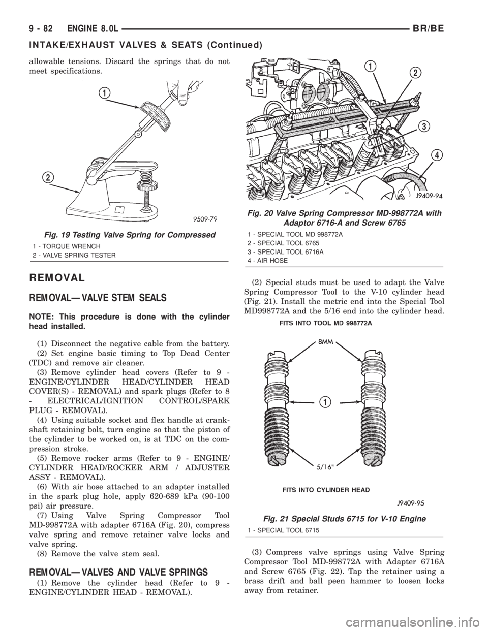
(7) Using Valve Spring Compressor Tool
MD-998772A with adapter 6716A (Fig. 20), compress
valve spring and remove retainer valve locks and
valve spring.
(8) Remove the valve stem seal.
REMOVALÐVALVES AND VALVE SPRINGS
(1) Remove the cylinder head (Refer to 9 -
ENGINE/CYLINDER HEAD - REMOVAL).(2) Special studs must be used to adapt the Valve
Spring Compressor Tool to the V-10 cylinder head
(Fig. 21). Install the metric end into the Special Tool
MD998772A and the 5/16 end into the cylinder head.
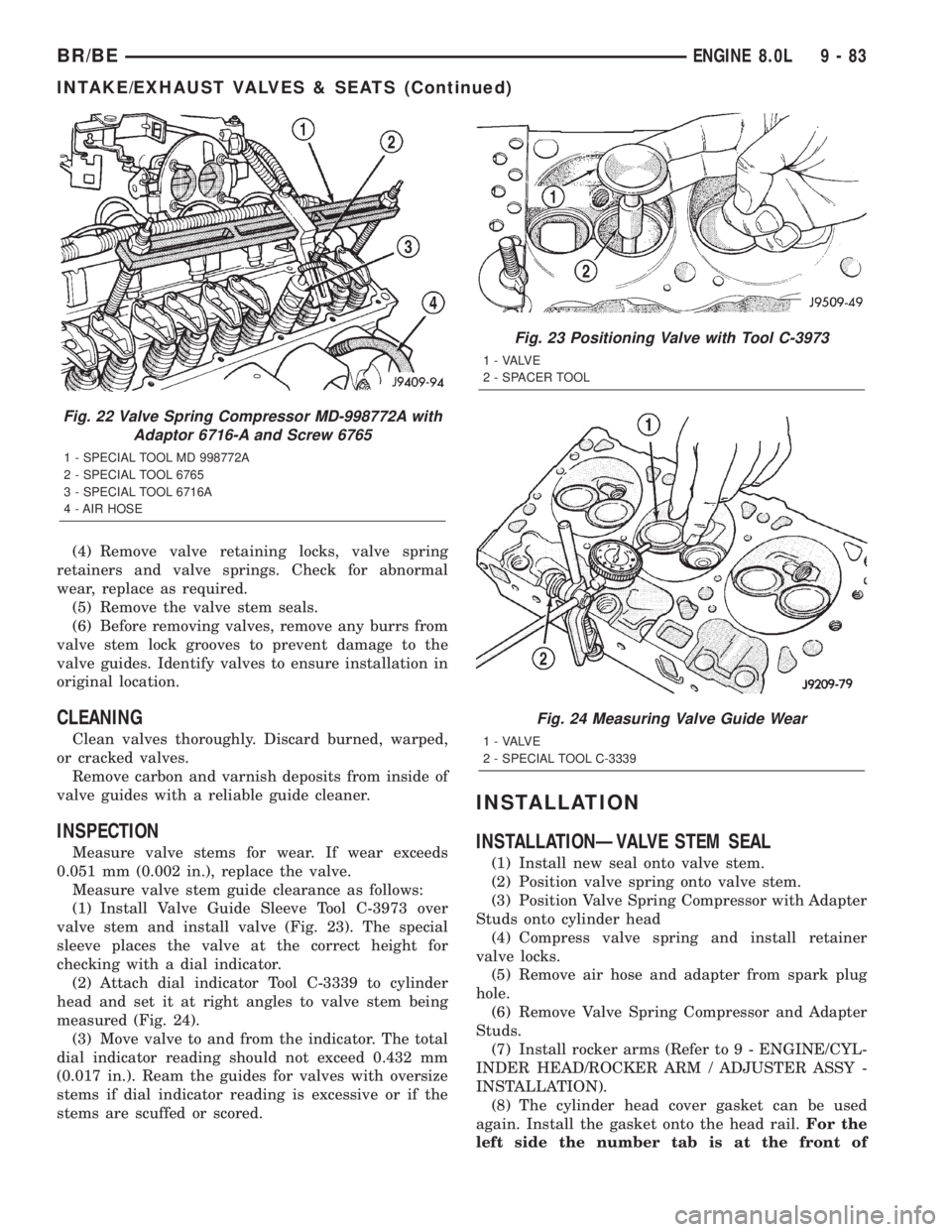
(3) Compress valve springs using Valve Spring
Compressor Tool MD-998772A with Adapter 6716A
and Screw 6765 (Fig. 22). Tap the retainer using a
brass drift and ball peen hammer to loosen locks
away from retainer.
Fig. 19 Testing Valve Spring for Compressed
1 - TORQUE WRENCH
2 - VALVE SPRING TESTER
Fig. 20 Valve Spring Compressor MD-998772A with
Adaptor 6716-A and Screw 6765
1 - SPECIAL TOOL MD 998772A
2 - SPECIAL TOOL 6765
3 - SPECIAL TOOL 6716A
4 - AIR HOSE
Fig. 21 Special Studs 6715 for V-10 Engine
1 - SPECIAL TOOL 6715
9 - 82 ENGINE 8.0LBR/BE
INTAKE/EXHAUST VALVES & SEATS (Continued)
Page 1158 of 2255
(4) Remove valve retaining locks, valve spring
retainers and valve springs. Check for abnormal
wear, replace as required.
(5) Remove the valve stem seals.
(6) Before removing valves, remove any burrs from
valve stem lock grooves to prevent damage to the
valve guides. Identify valves to ensure installation in
original location.
CLEANING
Clean valves thoroughly. Discard burned, warped,
or cracked valves.
Remove carbon and varnish deposits from inside of
valve guides with a reliable guide cleaner.
INSPECTION
Measure valve stems for wear. If wear exceeds
0.051 mm (0.002 in.), replace the valve.
Measure valve stem guide clearance as follows:
(1) Install Valve Guide Sleeve Tool C-3973 over
valve stem and install valve (Fig. 23). The special
sleeve places the valve at the correct height for
checking with a dial indicator.
(2) Attach dial indicator Tool C-3339 to cylinder
head and set it at right angles to valve stem being
measured (Fig. 24).
(3) Move valve to and from the indicator. The total
dial indicator reading should not exceed 0.432 mm
(0.017 in.). Ream the guides for valves with oversize
stems if dial indicator reading is excessive or if the
stems are scuffed or scored.
INSTALLATION
INSTALLATIONÐVALVE STEM SEAL
(1) Install new seal onto valve stem.
(2) Position valve spring onto valve stem.
(3) Position Valve Spring Compressor with Adapter
Studs onto cylinder head
(4) Compress valve spring and install retainer
valve locks.
(5) Remove air hose and adapter from spark plug
hole.
(6) Remove Valve Spring Compressor and Adapter
Studs.
(7) Install rocker arms (Refer to 9 - ENGINE/CYL-
INDER HEAD/ROCKER ARM / ADJUSTER ASSY -
INSTALLATION).
(8) The cylinder head cover gasket can be used
again. Install the gasket onto the head rail.For the
left side the number tab is at the front of
Fig. 22 Valve Spring Compressor MD-998772A with
Adaptor 6716-A and Screw 6765
1 - SPECIAL TOOL MD 998772A
2 - SPECIAL TOOL 6765
3 - SPECIAL TOOL 6716A
4 - AIR HOSE
Fig. 23 Positioning Valve with Tool C-3973
1 - VALVE
2 - SPACER TOOL
Fig. 24 Measuring Valve Guide Wear
1 - VALVE
2 - SPECIAL TOOL C-3339
BR/BEENGINE 8.0L 9 - 83
INTAKE/EXHAUST VALVES & SEATS (Continued)
Page 1159 of 2255
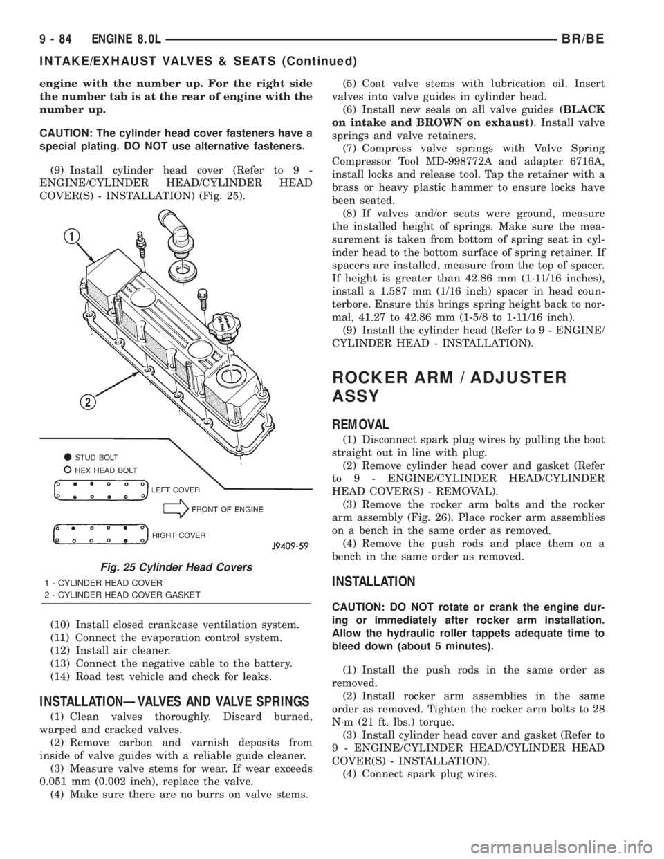
engine with the number up. For the right side
the number tab is at the rear of engine with the
number up.
CAUTION: The cylinder head cover fasteners have a
special plating. DO NOT use alternative fasteners.
(9) Install cylinder head cover (Refer to 9 -
ENGINE/CYLINDER HEAD/CYLINDER HEAD
COVER(S) - INSTALLATION) (Fig. 25).
(10) Install closed crankcase ventilation system.
(11) Connect the evaporation control system.
(12) Install air cleaner.
(13) Connect the negative cable to the battery.
(14) Road test vehicle and check for leaks.
INSTALLATIONÐVALVES AND VALVE SPRINGS
(1) Clean valves thoroughly. Discard burned,
warped and cracked valves.
(2) Remove carbon and varnish deposits from
inside of valve guides with a reliable guide cleaner.
(3) Measure valve stems for wear. If wear exceeds
0.051 mm (0.002 inch), replace the valve.
(4) Make sure there are no burrs on valve stems.(5) Coat valve stems with lubrication oil. Insert
valves into valve guides in cylinder head.
(6) Install new seals on all valve guides(BLACK
on intake and BROWN on exhaust). Install valve
springs and valve retainers.
(7) Compress valve springs with Valve Spring
Compressor Tool MD-998772A and adapter 6716A,
install locks and release tool. Tap the retainer with a
brass or heavy plastic hammer to ensure locks have
been seated.
(8) If valves and/or seats were ground, measure
the installed height of springs. Make sure the mea-
surement is taken from bottom of spring seat in cyl-
inder head to the bottom surface of spring retainer. If
spacers are installed, measure from the top of spacer.
If height is greater than 42.86 mm (1-11/16 inches),
install a 1.587 mm (1/16 inch) spacer in head coun-
terbore. Ensure this brings spring height back to nor-
mal, 41.27 to 42.86 mm (1-5/8 to 1-11/16 inch).
(9) Install the cylinder head (Refer to 9 - ENGINE/
CYLINDER HEAD - INSTALLATION).
ROCKER ARM / ADJUSTER
ASSY
REMOVAL
(1) Disconnect spark plug wires by pulling the boot
straight out in line with plug.
(2) Remove cylinder head cover and gasket (Refer
to 9 - ENGINE/CYLINDER HEAD/CYLINDER
HEAD COVER(S) - REMOVAL).
(3) Remove the rocker arm bolts and the rocker
arm assembly (Fig. 26). Place rocker arm assemblies
on a bench in the same order as removed.
(4) Remove the push rods and place them on a
bench in the same order as removed.
INSTALLATION
CAUTION: DO NOT rotate or crank the engine dur-
ing or immediately after rocker arm installation.
Allow the hydraulic roller tappets adequate time to
bleed down (about 5 minutes).
(1) Install the push rods in the same order as
removed.
(2) Install rocker arm assemblies in the same
order as removed. Tighten the rocker arm bolts to 28
N´m (21 ft. lbs.) torque.
(3) Install cylinder head cover and gasket (Refer to
9 - ENGINE/CYLINDER HEAD/CYLINDER HEAD
COVER(S) - INSTALLATION).
(4) Connect spark plug wires.
Fig. 25 Cylinder Head Covers
1 - CYLINDER HEAD COVER
2 - CYLINDER HEAD COVER GASKET
9 - 84 ENGINE 8.0LBR/BE
INTAKE/EXHAUST VALVES & SEATS (Continued)
Page 1161 of 2255
INSTALLATION
INSTALLATIONÐCAMSHAFT BEARINGS
(1) Install new camshaft bearings using recom-
mended Tool 8544 Camshaft Bushing Remover
Installer, by sliding the new camshaft bearing shell
over proper adapter.
(2) Bearings must be carefully aligned to bring oil
holes into full register with oil passages from the
main bearing. If the camshaft bearing shell oil holes
are not in exact alignment, remove and install them
correctly. Install a new core hole plug at the rear of
camshaft.Be sure this plug does not leak.
INSTALLATIONÐCAMSHAFT
(1) Lubricate camshaft lobes and camshaft bearing
journals. Using a long bolt, insert the camshaft into
the cylinder block.
NOTE: Whenever an engine has been rebuilt, a new
camshaft and/or new tappets installed, add 1 pint of
MoparTCrankcase Conditioner, or equivalent. The
oil mixture should be left in engine for a minimum
of 805 km (500 miles). Drain at the next normal oil
change.
(2) Install camshaft thrust plate. Tighten the torx
bolts to 22 N´m (16 ft. lbs.) torque.
(3) Check camshaft end play. The end play should
be 0.051-0.152 mm (0.002-0.006 inch) with a new
thrust plate and up to 0.254 mm (0.010 inch) with a
used thrust plate. If not within these limits install a
new thrust plate.
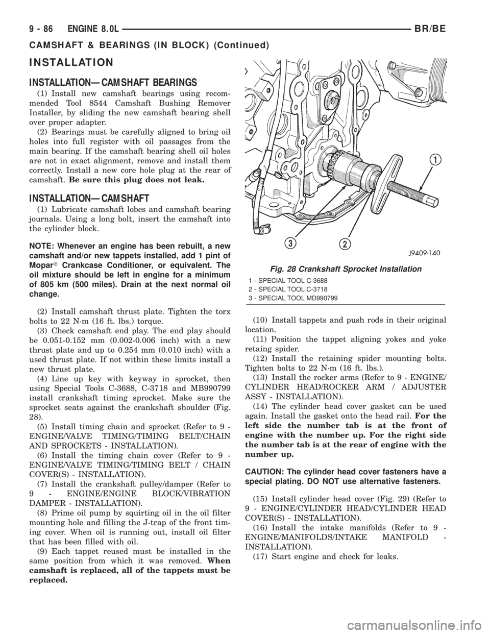
(4) Line up key with keyway in sprocket, then
using Special Tools C-3688, C-3718 and MB990799
install crankshaft timing sprocket. Make sure the
sprocket seats against the crankshaft shoulder (Fig.
28).
(5) Install timing chain and sprocket (Refer to 9 -
ENGINE/VALVE TIMING/TIMING BELT/CHAIN
AND SPROCKETS - INSTALLATION).
(6) Install the timing chain cover (Refer to 9 -
ENGINE/VALVE TIMING/TIMING BELT / CHAIN
COVER(S) - INSTALLATION).
(7) Install the crankshaft pulley/damper (Refer to
9 - ENGINE/ENGINE BLOCK/VIBRATION
DAMPER - INSTALLATION).
(8) Prime oil pump by squirting oil in the oil filter
mounting hole and filling the J-trap of the front tim-
ing cover. When oil is running out, install oil filter
that has been filled with oil.
(9) Each tappet reused must be installed in the
same position from which it was removed.When
camshaft is replaced, all of the tappets must be
replaced.(10) Install tappets and push rods in their original
location.
(11) Position the tappet aligning yokes and yoke
retaing spider.
(12) Install the retaining spider mounting bolts.
Tighten bolts to 22 N´m (16 ft. lbs.).
(13) Install the rocker arms (Refer to 9 - ENGINE/
CYLINDER HEAD/ROCKER ARM / ADJUSTER
ASSY - INSTALLATION).
(14) The cylinder head cover gasket can be used
again. Install the gasket onto the head rail.For the
left side the number tab is at the front of
engine with the number up. For the right side
the number tab is at the rear of engine with the
number up.
CAUTION: The cylinder head cover fasteners have a
special plating. DO NOT use alternative fasteners.
(15) Install cylinder head cover (Fig. 29) (Refer to
9 - ENGINE/CYLINDER HEAD/CYLINDER HEAD
COVER(S) - INSTALLATION).
(16) Install the intake manifolds (Refer to 9 -
ENGINE/MANIFOLDS/INTAKE MANIFOLD -
INSTALLATION).
(17) Start engine and check for leaks.
Fig. 28 Crankshaft Sprocket Installation
1 - SPECIAL TOOL C-3688
2 - SPECIAL TOOL C-3718
3 - SPECIAL TOOL MD990799
9 - 86 ENGINE 8.0LBR/BE
CAMSHAFT & BEARINGS (IN BLOCK) (Continued)
Page 1196 of 2255
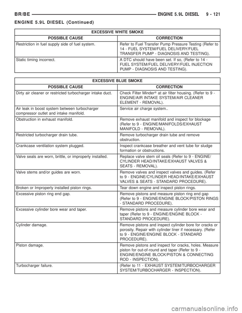
EXCESSIVE WHITE SMOKE
POSSIBLE CAUSE CORRECTION
Restriction in fuel supply side of fuel system. Refer to Fuel Transfer Pump Pressure Testing (Refer to
14 - FUEL SYSTEM/FUEL DELIVERY/FUEL
TRANSFER PUMP - DIAGNOSIS AND TESTING).
Static timing incorrect. A DTC should have been set. If so, (Refer to 14 -
FUEL SYSTEM/FUEL DELIVERY/FUEL INJECTION
PUMP - DIAGNOSIS AND TESTING).
EXCESSIVE BLUE SMOKE
POSSIBLE CAUSE CORRECTION
Dirty air cleaner or restricted turbocharger intake duct. Check Filter MinderTat air filter housing. (Refer to 9 -
ENGINE/AIR INTAKE SYSTEM/AIR CLEANER
ELEMENT - REMOVAL).
Air leak in boost system between turbocharger
compressor outlet and intake manifold.Service air charge system..
Obstruction in exhaust manifold. Remove exhaust manifold and inspect for blockage
(Refer to 9 - ENGINE/MANIFOLDS/EXHAUST
MANIFOLD - REMOVAL).
Restricted turbocharger drain tube. Remove turbocharger drain tube and remove
obstruction.
Crankcase ventilation system plugged. Inspect crankcase breather and vent tube for sludge
formation or obstructions.
Valve seals are worn, brittle, or improperly installed. Replace valve stem oil seals (Refer to 9 - ENGINE/
CYLINDER HEAD/INTAKE/EXHAUST VALVES &
SEATS - REMOVAL).
Valve stems and/or guides are worn. Remove valves and inspect valves and guides. (Refer
to 9 - ENGINE/CYLINDER HEAD/INTAKE/EXHAUST
VALVES & SEATS - STANDARD PROCEDURE).
Broken or Improperly installed piston rings. Tear down engine and inspect piston rings.
Excessive piston ring end gap. Remove pistons and measure piston ring end gap
(Refer to 9 - ENGINE/ENGINE BLOCK/PISTON RINGS
- STANDARD PROCEDURE).
Excessive cylinder bore wear and taper. Remove pistons and measure cylinder bore wear and
taper (Refer to 9 - ENGINE/ENGINE BLOCK -
STANDARD PROCEDURE).
Cylinder damage. Remove pistons and inspect cylinder bore for cracks or
porosity. Repair with cylinder liner if necessary. (Refer
to 9 - ENGINE/ENGINE BLOCK - STANDARD
PROCEDURE).
Piston damage. Remove pistons and inspect for cracks, holes. Measure
piston for out-of-round and taper (Refer to 9 -
ENGINE/ENGINE BLOCK/PISTON & CONNECTING
ROD - INSPECTION).
Turbocharger failure. (Refer to 11 - EXHAUST SYSTEM/TURBOCHARGER
SYSTEM/TURBOCHARGER - INSPECTION).
BR/BEENGINE 5.9L DIESEL 9 - 121
ENGINE 5.9L DIESEL (Continued)
Page 1211 of 2255
INSTALLATION
WARNING: THE OUTSIDE EDGE OF THE HEAD
GASKET IS VERY SHARP. WHEN HANDLING THE
NEW HEAD GASKET, USE CARE NOT TO INJURE
YOURSELF.
(1) Install a new gasket with the part number side
up, and locate the gasket over the dowel sleeves.
(2) Using an engine lifting crane, lower the cylin-
der head onto the engine.
(3) Lightly lubricate head bolts with engine oil and
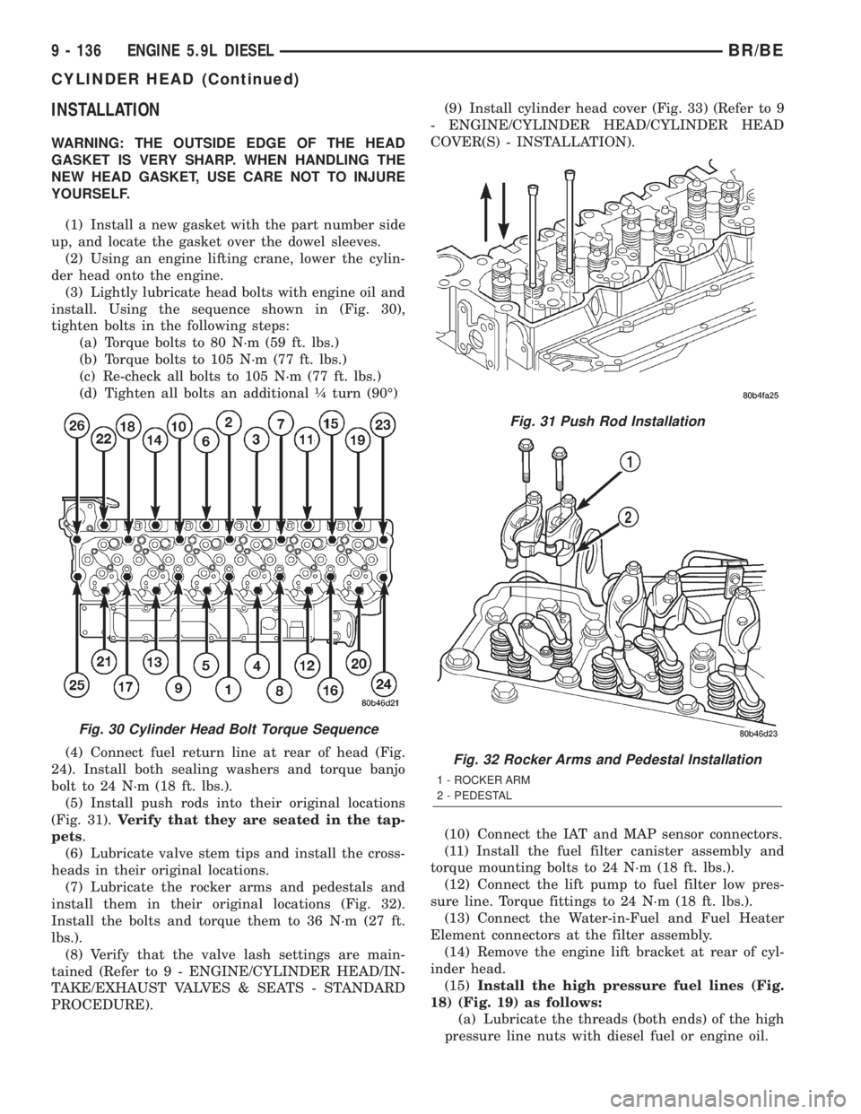
install. Using the sequence shown in (Fig. 30),
tighten bolts in the following steps:
(a) Torque bolts to 80 N´m (59 ft. lbs.)
(b) Torque bolts to 105 N´m (77 ft. lbs.)
(c) Re-check all bolts to 105 N´m (77 ft. lbs.)
(d) Tighten all bolts an additional ò turn (90É)
(4) Connect fuel return line at rear of head (Fig.
24). Install both sealing washers and torque banjo
bolt to 24 N´m (18 ft. lbs.).
(5) Install push rods into their original locations
(Fig. 31).Verify that they are seated in the tap-
pets.
(6) Lubricate valve stem tips and install the cross-
heads in their original locations.
(7) Lubricate the rocker arms and pedestals and
install them in their original locations (Fig. 32).
Install the bolts and torque them to 36 N´m (27 ft.
lbs.).
(8) Verify that the valve lash settings are main-
tained (Refer to 9 - ENGINE/CYLINDER HEAD/IN-
TAKE/EXHAUST VALVES & SEATS - STANDARD
PROCEDURE).(9) Install cylinder head cover (Fig. 33) (Refer to 9
- ENGINE/CYLINDER HEAD/CYLINDER HEAD
COVER(S) - INSTALLATION).
(10) Connect the IAT and MAP sensor connectors.
(11) Install the fuel filter canister assembly and
torque mounting bolts to 24 N´m (18 ft. lbs.).
(12) Connect the lift pump to fuel filter low pres-
sure line. Torque fittings to 24 N´m (18 ft. lbs.).
(13) Connect the Water-in-Fuel and Fuel Heater
Element connectors at the filter assembly.
(14) Remove the engine lift bracket at rear of cyl-
inder head.
(15)Install the high pressure fuel lines (Fig.
18) (Fig. 19) as follows:
(a) Lubricate the threads (both ends) of the high
pressure line nuts with diesel fuel or engine oil.
Fig. 30 Cylinder Head Bolt Torque Sequence
Fig. 31 Push Rod Installation
Fig. 32 Rocker Arms and Pedestal Installation
1 - ROCKER ARM
2 - PEDESTAL
9 - 136 ENGINE 5.9L DIESELBR/BE
CYLINDER HEAD (Continued)
Page 1213 of 2255
INSPECTION
The cylinder head cover gasket and isolators
are reusable.However, should cracks be present in
the rubber/silicone construction, the defective compo-
nents should be replaced.
INSTALLATION
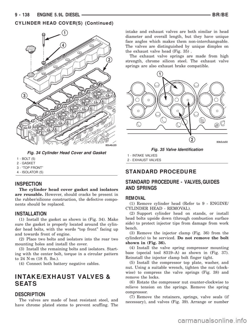
(1) Install the gasket as shown in (Fig. 34). Make
sure the gasket is properly located around the cylin-
der head bolts, with the words ªtop frontº facing up
and towards front of engine.
(2) Place two bolts and isolators into the rear two
mounting holes and install the cover.
(3) Install the remaining bolts and isolators. Start-
ing with the center bolt, torque in a circular pattern
to 24 N´m (18 ft. lbs.).
(4) Connect both battery negative cables.
INTAKE/EXHAUST VALVES &
SEATS
DESCRIPTION
The valves are made of heat resistant steel, and
have chrome plated stems to prevent scuffing. Theintake and exhaust valves are both similar in head
diameter and overall length, but they have unique
face angles which makes them non-interchangeable.
The valves are distinguished by unique dimples on
the exhaust valve head (Fig. 35) .
The exhaust valve springs are made from high
strength, chrome silicon steel. The exhaust valve
springs are also exhaust brake compatible.
STANDARD PROCEDURE
STANDARD PROCEDURE - VALVES,GUIDES
AND SPRINGS
REMOVAL
(1) Remove cylinder head (Refer to 9 - ENGINE/
CYLINDER HEAD - REMOVAL).
(2) Support cylinder head on stands, or install
head bolts upside down (through combustion surface
side) to protect injector tips from damage from work
bench.
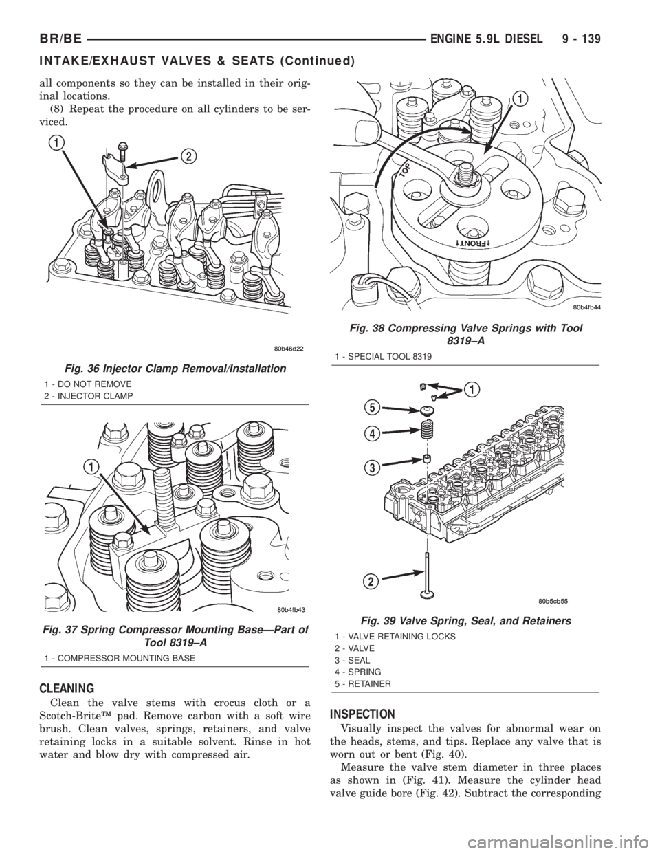
(3) Remove the injector clamp (Fig. 36) from the
cylinder(s) to be serviced.Do not remove the bolt
shown in (Fig. 36).
(4) Install the valve spring compressor mounting
base (special tool 8319±A) as shown in (Fig. 37).
Reinstall the injector clamp bolt finger tight.
(5) Install the compressor top plate, washer, and
nut. Using a suitable wrench, tighten the nut (clock-
wise) to compress the valve springs (Fig. 38) and
remove the locks.
(6) Rotate the compressor nut counter-clockwise to
relieve tension on the springs. Remove the spring
compressor.
(7) Remove the retainers, springs, valve seals (if
necessary), and valves (Fig. 39). Arrange or number
Fig. 34 Cylinder Head Cover and Gasket
1 - BOLT (5)
2 - GASKET
3 - ªTOP FRONTº
4 - ISOLATOR (5)
Fig. 35 Valve Identification
1 - INTAKE VALVES
2 - EXHAUST VALVES
9 - 138 ENGINE 5.9L DIESELBR/BE
CYLINDER HEAD COVER(S) (Continued)
Page 1214 of 2255
all components so they can be installed in their orig-
inal locations.
(8) Repeat the procedure on all cylinders to be ser-
viced.
CLEANING
Clean the valve stems with crocus cloth or a
Scotch-BriteŸ pad. Remove carbon with a soft wire
brush. Clean valves, springs, retainers, and valve
retaining locks in a suitable solvent. Rinse in hot
water and blow dry with compressed air.
INSPECTION
Visually inspect the valves for abnormal wear on
the heads, stems, and tips. Replace any valve that is
worn out or bent (Fig. 40).
Measure the valve stem diameter in three places
as shown in (Fig. 41). Measure the cylinder head
valve guide bore (Fig. 42). Subtract the corresponding
Fig. 36 Injector Clamp Removal/Installation
1 - DO NOT REMOVE
2 - INJECTOR CLAMP
Fig. 37 Spring Compressor Mounting BaseÐPart of
Tool 8319±A
1 - COMPRESSOR MOUNTING BASE
Fig. 38 Compressing Valve Springs with Tool
8319±A
1 - SPECIAL TOOL 8319
Fig. 39 Valve Spring, Seal, and Retainers
1 - VALVE RETAINING LOCKS
2 - VALVE
3 - SEAL
4 - SPRING
5 - RETAINER
BR/BEENGINE 5.9L DIESEL 9 - 139
INTAKE/EXHAUST VALVES & SEATS (Continued)