2002 DODGE RAM remove seats
[x] Cancel search: remove seatsPage 613 of 2255
(6) Install and tighten the screw that secures the
shoulder belt turning loop to the height adjuster.
Tighten the screw to 30 N´m (22 ft. lbs.).
(7) Fold and snap the cover over the front shoulder
belt turning loop to conceal the screw that secures
the turning loop to the height adjuster.
(8) Install and tighten the screw that secures the
lower seat belt anchor plate to the floor panel near
the base of the B-pillar. Tighten the screw to 40 N´m
(29 ft. lbs.).
INSTALLATION - CLUB/QUAD CAB
The front seat shoulder belt and retractor are inte-
gral to the driver and passenger front seat backs on
club cab and quad cab models.
WARNING: DURING AND FOLLOWING ANY SEAT
BELT SERVICE, CAREFULLY INSPECT ALL SEAT
BELTS, BUCKLES, MOUNTING HARDWARE, AND
RETRACTORS FOR PROPER INSTALLATION,
OPERATION, OR DAMAGE. REPLACE ANY BELT
THAT IS CUT, FRAYED, OR TORN. STRAIGHTEN
ANY BELT THAT IS TWISTED. TIGHTEN ANY
LOOSE FASTENERS. REPLACE ANY BELT THAT
HAS A DAMAGED OR INOPERATIVE BUCKLE OR
RETRACTOR. REPLACE ANY BELT THAT HAS A
BENT OR DAMAGED LATCH PLATE OR ANCHOR
PLATE. NEVER ATTEMPT TO REPAIR A SEAT BELT
COMPONENT. ALWAYS REPLACE DAMAGED OR
FAULTY SEAT BELT COMPONENTS WITH THE COR-
RECT, NEW AND UNUSED REPLACEMENT PARTS
LISTED IN THE MOPAR PARTS CATALOG.
(1) Position the front shoulder belt and retractor
onto the seat back frame.
(2) Install and tighten the two screws that secure
the seat belt retractor to the seat back frame (Fig.
16). Tighten the screws to 16 N´m (12 ft. lbs.).
(3) Position the retractor cover onto the seat back
frame.
(4) Install and tighten the screws that secure the
retractor cover to the seat back frame. Tighten the
screws to 2 N´m (17 in. lbs.).
(5) Reinstall the trim cover onto the front seat
back frame. (Refer to 23 - BODY/SEATS/SEAT BACK
COVER - INSTALLATION).
FRONT SEAT BELT BUCKLE
REMOVAL
WARNING: DURING AND FOLLOWING ANY SEAT
BELT SERVICE, CAREFULLY INSPECT ALL SEAT
BELTS, BUCKLES, MOUNTING HARDWARE, AND
RETRACTORS FOR PROPER INSTALLATION,
OPERATION, OR DAMAGE. REPLACE ANY BELTTHAT IS CUT, FRAYED, OR TORN. STRAIGHTEN
ANY BELT THAT IS TWISTED. TIGHTEN ANY
LOOSE FASTENERS. REPLACE ANY BELT THAT
HAS A DAMAGED OR INOPERATIVE BUCKLE OR
RETRACTOR. REPLACE ANY BELT THAT HAS A
BENT OR DAMAGED LATCH PLATE OR ANCHOR
PLATE. NEVER ATTEMPT TO REPAIR A SEAT BELT
COMPONENT. ALWAYS REPLACE DAMAGED OR
FAULTY SEAT BELT COMPONENTS WITH THE COR-
RECT, NEW AND UNUSED REPLACEMENT PARTS
LISTED IN THE MOPAR PARTS CATALOG.
(1) Move the front seat to its most forward position
for easiest access to the front seat belt buckle
anchors.
(2) Tilt both front seat backs forward far enough to
access the seat belt buckle anchor screws.
(3) On the driver's side only, disconnect the body
wire harness connector for the seat belt switch from
the seat belt switch pigtail wire connector on the seat
belt buckle.
(4) Remove the screw that secures the seat belt
buckle to the anchor on the seat cushion frame.
(5) Remove the front seat belt buckle from the seat
cushion frame.
INSTALLATION
WARNING: DURING AND FOLLOWING ANY SEAT
BELT SERVICE, CAREFULLY INSPECT ALL SEAT
BELTS, BUCKLES, MOUNTING HARDWARE, AND
RETRACTORS FOR PROPER INSTALLATION,
OPERATION, OR DAMAGE. REPLACE ANY BELT
THAT IS CUT, FRAYED, OR TORN. STRAIGHTEN
ANY BELT THAT IS TWISTED. TIGHTEN ANY
LOOSE FASTENERS. REPLACE ANY BELT THAT
HAS A DAMAGED OR INOPERATIVE BUCKLE OR
RETRACTOR. REPLACE ANY BELT THAT HAS A
BENT OR DAMAGED LATCH PLATE OR ANCHOR
PLATE. NEVER ATTEMPT TO REPAIR A SEAT BELT
COMPONENT. ALWAYS REPLACE DAMAGED OR
FAULTY SEAT BELT COMPONENTS WITH THE COR-
RECT, NEW AND UNUSED REPLACEMENT PARTS
LISTED IN THE MOPAR PARTS CATALOG.
(1) Position the front seat belt buckle onto the seat
cushion frame.
(2) On the driver's side only, reconnect the body
wire harness connector for the seat belt switch to the
seat belt switch pigtail wire connector on the seat
belt buckle.
(3) Install and tighten the screw that secures the
seat belt buckle to the anchor on the seat cushion
frame. Tighten the screw to 40 N´m (29 ft. lbs.).
8O - 20 RESTRAINTSBR/BE
FRONT SEAT BELT & RETRACTOR (Continued)
Page 619 of 2255
(5) Position the passenger airbag on/off switch and
face plate unit to the opening in the instrument
panel (Fig. 21).
(6) Install and tighten the three screws that secure
the passenger airbag on/off switch face plate to the
instrument panel. Tighten the screws to 2.2 N´m (20
in. lbs.).
(7) Reinstall the glove box onto the instrument
panel. (Refer to 23 - BODY/INSTRUMENT PANEL/
GLOVE BOX - INSTALLATION).
(8) Reinstall the cluster bezel onto the instrument
panel. (Refer to 23 - BODY/INSTRUMENT PANEL/
CLUSTER BEZEL - INSTALLATION).
(9) Do not reconnect the battery negative cable at
this time. The airbag system verification test proce-
dure should be performed following service of any
airbag system component. (Refer to 8 - ELECTRI-
CAL/RESTRAINTS - STANDARD PROCEDURE -
VERIFICATION TEST).
REAR SEAT BELT &
RETRACTOR
REMOVAL
WARNING: DURING AND FOLLOWING ANY SEAT
BELT SERVICE, CAREFULLY INSPECT ALL SEAT
BELTS, BUCKLES, MOUNTING HARDWARE, AND
RETRACTORS FOR PROPER INSTALLATION,
OPERATION, OR DAMAGE. REPLACE ANY BELT
THAT IS CUT, FRAYED, OR TORN. STRAIGHTEN
ANY BELT THAT IS TWISTED. TIGHTEN ANY
LOOSE FASTENERS. REPLACE ANY BELT THAT
HAS A DAMAGED OR INOPERATIVE BUCKLE OR
RETRACTOR. REPLACE ANY BELT THAT HAS A
BENT OR DAMAGED LATCH PLATE OR ANCHOR
PLATE. NEVER ATTEMPT TO REPAIR A SEAT BELT
COMPONENT. ALWAYS REPLACE DAMAGED OR
FAULTY SEAT BELT COMPONENTS WITH THE COR-
RECT, NEW AND UNUSED REPLACEMENT PARTS
LISTED IN THE MOPAR PARTS CATALOG.
(1) Remove the rear seat from the passenger com-
partment. (Refer to 23 - BODY/SEATS/REAR SEAT -
REMOVAL).
(2) Remove the trim cover from the door sill.
(Refer to 23 - BODY/INTERIOR/DOOR SILL TRIM -
REMOVAL).
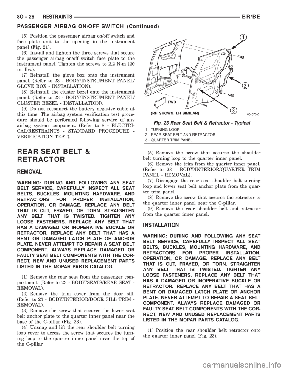
(3) Remove the screw that secures the lower seat
belt anchor plate to the quarter inner panel near the
base of the C-pillar (Fig. 23).
(4) Unsnap and lift the rear shoulder belt turning
loop cover to access the screw that secures the turn-
ing loop to the quarter inner panel near the top of
the C-pillar.(5) Remove the screw that secures the shoulder
belt turning loop to the quarter inner panel.
(6) Remove the trim from the quarter inner panel.
(Refer to 23 - BODY/INTERIOR/QUARTER TRIM
PANEL - REMOVAL).
(7) Disengage the rear seat shoulder belt turning
loop and lower seat belt anchor plate from the quar-
ter trim panel.
(8) Remove the screw that secures the retractor to
the quarter inner panel near the C-pillar.
(9) Remove the rear shoulder belt and retractor
from the quarter inner panel.
INSTALLATION
WARNING: DURING AND FOLLOWING ANY SEAT
BELT SERVICE, CAREFULLY INSPECT ALL SEAT
BELTS, BUCKLES, MOUNTING HARDWARE, AND
RETRACTORS FOR PROPER INSTALLATION,
OPERATION, OR DAMAGE. REPLACE ANY BELT
THAT IS CUT, FRAYED, OR TORN. STRAIGHTEN
ANY BELT THAT IS TWISTED. TIGHTEN ANY
LOOSE FASTENERS. REPLACE ANY BELT THAT
HAS A DAMAGED OR INOPERATIVE BUCKLE OR
RETRACTOR. REPLACE ANY BELT THAT HAS A
BENT OR DAMAGED LATCH PLATE OR ANCHOR
PLATE. NEVER ATTEMPT TO REPAIR A SEAT BELT
COMPONENT. ALWAYS REPLACE DAMAGED OR
FAULTY SEAT BELT COMPONENTS WITH THE COR-
RECT, NEW AND UNUSED REPLACEMENT PARTS
LISTED IN THE MOPAR PARTS CATALOG.
(1) Position the rear shoulder belt retractor onto
the quarter inner panel (Fig. 23).
Fig. 23 Rear Seat Belt & Retractor - Typical
1 - TURNING LOOP
2 - REAR SEAT BELT AND RETRACTOR
3 - QUARTER TRIM PANEL
8O - 26 RESTRAINTSBR/BE
PASSENGER AIRBAG ON/OFF SWITCH (Continued)
Page 620 of 2255
(2) Install and tighten the screw that secures the
retractor to the quarter inner panel. Tighten the
screw to 40 N´m (29 ft. lbs.).
(3) Engage the rear seat shoulder belt turning loop
and lower seat belt anchor plate with the quarter
trim panel.
(4) Reinstall the trim onto the quarter inner panel.
(Refer to 23 - BODY/INTERIOR/QUARTER TRIM
PANEL - INSTALLATION).
(5) Position the shoulder belt turning loop onto the
quarter inner panel near the top of the C-pillar.
(6) Install and tighten the screw that secures the
shoulder belt turning loop to the quarter inner panel.
Tighten the screw to 40 N´m (29 ft. lbs.).
(7) Fold and snap the cover over the rear shoulder
belt turning loop to conceal the screw that secures
the turning loop to the quarter inner panel.
(8) Position the lower seat belt anchor plate onto
the quarter inner panel near the base of the C-pillar.
(9) Install and tighten the screw that secures the
lower seat belt anchor plate to the quarter inner
panel near the base of the C-pillar. Tighten the screw
to 40 N´m (29 ft. lbs.).
(10) Reinstall the trim cover onto the door sill.
(Refer to 23 - BODY/INTERIOR/DOOR SILL TRIM -
INSTALLATION).
(11) Reinstall the rear seat into the passenger
compartment. (Refer to 23 - BODY/SEATS/REAR
SEAT - INSTALLATION).
REAR SEAT BELT BUCKLE
REMOVAL
WARNING: DURING AND FOLLOWING ANY SEAT
BELT SERVICE, CAREFULLY INSPECT ALL SEAT
BELTS, BUCKLES, MOUNTING HARDWARE, AND
RETRACTORS FOR PROPER INSTALLATION,
OPERATION, OR DAMAGE. REPLACE ANY BELT
THAT IS CUT, FRAYED, OR TORN. STRAIGHTEN
ANY BELT THAT IS TWISTED. TIGHTEN ANY
LOOSE FASTENERS. REPLACE ANY BELT THAT
HAS A DAMAGED OR INOPERATIVE BUCKLE OR
RETRACTOR. REPLACE ANY BELT THAT HAS A
BENT OR DAMAGED LATCH PLATE OR ANCHOR
PLATE. NEVER ATTEMPT TO REPAIR A SEAT BELT
COMPONENT. ALWAYS REPLACE DAMAGED OR
FAULTY SEAT BELT COMPONENTS WITH THE COR-
RECT, NEW AND UNUSED REPLACEMENT PARTS
LISTED IN THE MOPAR PARTS CATALOG.
(1) Disengage the rear seat latch by pulling the
release handle on the underside of the rear seat
cushion.(2) Fold the rear seat unit up and back against the
cab back panel (stowed position) for access to the
rear seat belt buckle anchors.
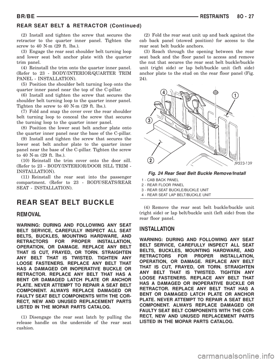
(3) Reach through the opening between the rear
seat back and the floor panel to access and remove
the nut that secures the rear seat belt buckle/buckle
unit (right side) or lap belt/buckle unit (left side)
anchor plate to the stud on the rear floor panel (Fig.
24).
(4) Remove the rear seat belt buckle/buckle unit
(right side) or lap belt/buckle unit (left side) from the
rear floor panel.INSTALLATION
WARNING: DURING AND FOLLOWING ANY SEAT
BELT SERVICE, CAREFULLY INSPECT ALL SEAT
BELTS, BUCKLES, MOUNTING HARDWARE, AND
RETRACTORS FOR PROPER INSTALLATION,
OPERATION, OR DAMAGE. REPLACE ANY BELT
THAT IS CUT, FRAYED, OR TORN. STRAIGHTEN
ANY BELT THAT IS TWISTED. TIGHTEN ANY
LOOSE FASTENERS. REPLACE ANY BELT THAT
HAS A DAMAGED OR INOPERATIVE BUCKLE OR
RETRACTOR. REPLACE ANY BELT THAT HAS A
BENT OR DAMAGED LATCH PLATE OR ANCHOR
PLATE. NEVER ATTEMPT TO REPAIR A SEAT BELT
COMPONENT. ALWAYS REPLACE DAMAGED OR
FAULTY SEAT BELT COMPONENTS WITH THE COR-
RECT, NEW AND UNUSED REPLACEMENT PARTS
LISTED IN THE MOPAR PARTS CATALOG.
Fig. 24 Rear Seat Belt Buckle Remove/Install
1 - CAB BACK PANEL
2 - REAR FLOOR PANEL
3 - REAR SEAT BUCKLE/BUCKLE UNIT
4 - REAR SEAT LAP BELT/BUCKLE UNIT
BR/BERESTRAINTS 8O - 27
REAR SEAT BELT & RETRACTOR (Continued)
Page 1098 of 2255
CYLINDER HEAD COVER(S)
REMOVAL
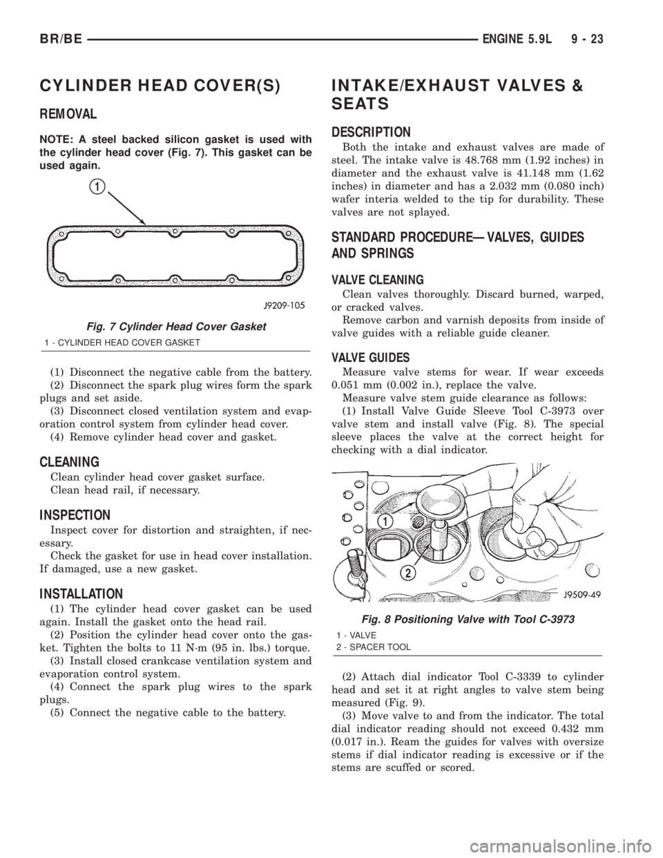
NOTE: A steel backed silicon gasket is used with
the cylinder head cover (Fig. 7). This gasket can be
used again.
(1) Disconnect the negative cable from the battery.
(2) Disconnect the spark plug wires form the spark
plugs and set aside.
(3) Disconnect closed ventilation system and evap-
oration control system from cylinder head cover.
(4) Remove cylinder head cover and gasket.
CLEANING
Clean cylinder head cover gasket surface.
Clean head rail, if necessary.
INSPECTION
Inspect cover for distortion and straighten, if nec-
essary.
Check the gasket for use in head cover installation.
If damaged, use a new gasket.
INSTALLATION
(1) The cylinder head cover gasket can be used
again. Install the gasket onto the head rail.
(2) Position the cylinder head cover onto the gas-
ket. Tighten the bolts to 11 N´m (95 in. lbs.) torque.
(3) Install closed crankcase ventilation system and
evaporation control system.
(4) Connect the spark plug wires to the spark
plugs.
(5) Connect the negative cable to the battery.
INTAKE/EXHAUST VALVES &
SEATS
DESCRIPTION
Both the intake and exhaust valves are made of
steel. The intake valve is 48.768 mm (1.92 inches) in
diameter and the exhaust valve is 41.148 mm (1.62
inches) in diameter and has a 2.032 mm (0.080 inch)
wafer interia welded to the tip for durability. These
valves are not splayed.
STANDARD PROCEDUREÐVALVES, GUIDES
AND SPRINGS
VALVE CLEANING
Clean valves thoroughly. Discard burned, warped,
or cracked valves.
Remove carbon and varnish deposits from inside of
valve guides with a reliable guide cleaner.
VALVE GUIDES
Measure valve stems for wear. If wear exceeds
0.051 mm (0.002 in.), replace the valve.
Measure valve stem guide clearance as follows:
(1) Install Valve Guide Sleeve Tool C-3973 over
valve stem and install valve (Fig. 8). The special
sleeve places the valve at the correct height for
checking with a dial indicator.
(2) Attach dial indicator Tool C-3339 to cylinder
head and set it at right angles to valve stem being
measured (Fig. 9).
(3) Move valve to and from the indicator. The total
dial indicator reading should not exceed 0.432 mm
(0.017 in.). Ream the guides for valves with oversize
stems if dial indicator reading is excessive or if the
stems are scuffed or scored.
Fig. 7 Cylinder Head Cover Gasket
1 - CYLINDER HEAD COVER GASKET
Fig. 8 Positioning Valve with Tool C-3973
1 - VALVE
2 - SPACER TOOL
BR/BEENGINE 5.9L 9 - 23
Page 1100 of 2255
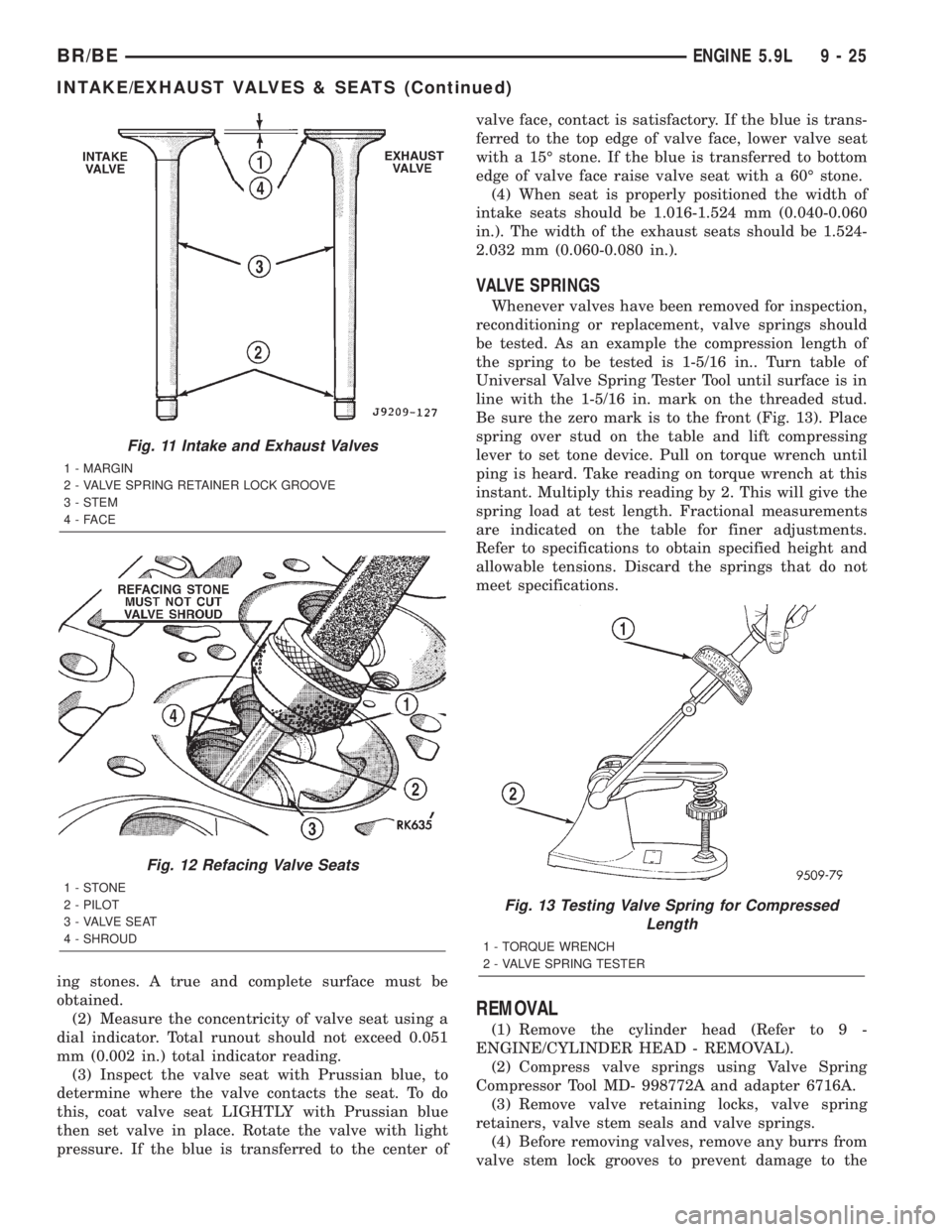
ing stones. A true and complete surface must be
obtained.
(2) Measure the concentricity of valve seat using a
dial indicator. Total runout should not exceed 0.051
mm (0.002 in.) total indicator reading.
(3) Inspect the valve seat with Prussian blue, to
determine where the valve contacts the seat. To do
this, coat valve seat LIGHTLY with Prussian blue
then set valve in place. Rotate the valve with light
pressure. If the blue is transferred to the center ofvalve face, contact is satisfactory. If the blue is trans-
ferred to the top edge of valve face, lower valve seat
with a 15É stone. If the blue is transferred to bottom
edge of valve face raise valve seat with a 60É stone.
(4) When seat is properly positioned the width of
intake seats should be 1.016-1.524 mm (0.040-0.060
in.). The width of the exhaust seats should be 1.524-
2.032 mm (0.060-0.080 in.).
VALVE SPRINGS
Whenever valves have been removed for inspection,
reconditioning or replacement, valve springs should
be tested. As an example the compression length of
the spring to be tested is 1-5/16 in.. Turn table of
Universal Valve Spring Tester Tool until surface is in
line with the 1-5/16 in. mark on the threaded stud.
Be sure the zero mark is to the front (Fig. 13). Place
spring over stud on the table and lift compressing
lever to set tone device. Pull on torque wrench until
ping is heard. Take reading on torque wrench at this
instant. Multiply this reading by 2. This will give the
spring load at test length. Fractional measurements
are indicated on the table for finer adjustments.
Refer to specifications to obtain specified height and
allowable tensions. Discard the springs that do not
meet specifications.
REMOVAL
(1) Remove the cylinder head (Refer to 9 -
ENGINE/CYLINDER HEAD - REMOVAL).
(2) Compress valve springs using Valve Spring
Compressor Tool MD- 998772A and adapter 6716A.
(3) Remove valve retaining locks, valve spring
retainers, valve stem seals and valve springs.
(4) Before removing valves, remove any burrs from
valve stem lock grooves to prevent damage to the
Fig. 11 Intake and Exhaust Valves
1 - MARGIN
2 - VALVE SPRING RETAINER LOCK GROOVE
3 - STEM
4-FACE
Fig. 12 Refacing Valve Seats
1-STONE
2 - PILOT
3 - VALVE SEAT
4 - SHROUD
Fig. 13 Testing Valve Spring for Compressed
Length
1 - TORQUE WRENCH
2 - VALVE SPRING TESTER
BR/BEENGINE 5.9L 9 - 25
INTAKE/EXHAUST VALVES & SEATS (Continued)
Page 1101 of 2255
valve guides. Identify valves to ensure installation in
original location.
CLEANING
Clean valves thoroughly. Discard burned, warped,
or cracked valves.
Remove carbon and varnish deposits from inside of
valve guides with a reliable guide cleaner.
INSPECTION
Measure valve stems for wear. If wear exceeds
0.051 mm (0.002 in.), replace the valve.
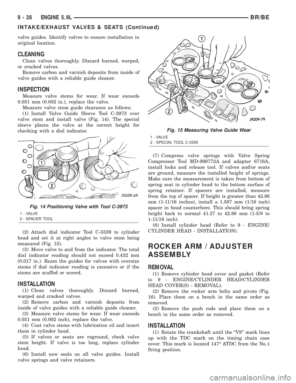
Measure valve stem guide clearance as follows:
(1) Install Valve Guide Sleeve Tool C-3973 over
valve stem and install valve (Fig. 14). The special
sleeve places the valve at the correct height for
checking with a dial indicator.
(2) Attach dial indicator Tool C-3339 to cylinder
head and set it at right angles to valve stem being
measured (Fig. 15).
(3) Move valve to and from the indicator. The total
dial indicator reading should not exceed 0.432 mm
(0.017 in.). Ream the guides for valves with oversize
stems if dial indicator reading is excessive or if the
stems are scuffed or scored.
INSTALLATION
(1) Clean valves thoroughly. Discard burned,
warped and cracked valves.
(2) Remove carbon and varnish deposits from
inside of valve guides with a reliable guide cleaner.
(3) Measure valve stems for wear. If wear exceeds
0.051 mm (0.002 inch), replace the valve.
(4) Coat valve stems with lubrication oil and insert
them in cylinder head.
(5) If valves or seats are reground, check valve
stem height. If valve is too long, replace cylinder
head.
(6) Install new seals on all valve guides. Install
valve springs and valve retainers.(7) Compress valve springs with Valve Spring
Compressor Tool MD-998772A and adapter 6716A,
install locks and release tool. If valves and/or seats
are ground, measure the installed height of springs.
Make sure the measurement is taken from bottom of
spring seat in cylinder head to the bottom surface of
spring retainer. If spacers are installed, measure
from the top of spacer. If height is greater than 42.86
mm (1-11/16 inches), install a 1.587 mm (1/16 inch)
spacer in head counterbore. This should bring spring
height back to normal 41.27 to 42.86 mm (1-5/8 to
1-11/16 inch).
(8) Install cylinder head (Refer to 9 - ENGINE/
CYLINDER HEAD - INSTALLATION).
ROCKER ARM / ADJUSTER
ASSEMBLY
REMOVAL
(1) Remove cylinder head cover and gasket (Refer
to 9 - ENGINE/CYLINDER HEAD/CYLINDER
HEAD COVER(S) - REMOVAL).
(2) Remove the rocker arm bolts and pivots (Fig.
16). Place them on a bench in the same order as
removed.
(3) Remove the push rods and place them on a
bench in the same order as removed.
INSTALLATION
(1) Rotate the crankshaft until the ªV8º mark lines
up with the TDC mark on the timing chain case
cover. This mark is located 147É ATDC from the No.1
firing position.
Fig. 14 Positioning Valve with Tool C-3973
1 - VALVE
2 - SPACER TOOL
Fig. 15 Measuring Valve Guide Wear
1 - VALVE
2 - SPECIAL TOOL C-3339
9 - 26 ENGINE 5.9LBR/BE
INTAKE/EXHAUST VALVES & SEATS (Continued)
Page 1131 of 2255
ENGINE 8.0L
TABLE OF CONTENTS
page page
ENGINE 8.0L
DESCRIPTION.........................58
DIAGNOSIS AND TESTING
DIAGNOSIS AND TESTING - ENGINE
DIAGNOSIS - INTRODUCTION...........58
DIAGNOSIS AND TESTINGÐENGINE
DIAGNOSIS - PERFORMANCE...........59
DIAGNOSIS AND TESTINGÐ ENGINE
DIAGNOSIS - MECHANICAL.............61
DIAGNOSIS AND TESTINGÐENGINE
DIAGNOSIS - LUBRICATION.............63
DIAGNOSIS AND TESTINGÐCYLINDER
COMPRESSION PRESSURE.............64
DIAGNOSIS AND TESTING - CYLINDER
COMBUSTION PRESSURE LEAKAGE......64
STANDARD PROCEDURE
STANDARD PROCEDUREÐCYLINDER
BORE HONING.......................65
STANDARD PROCEDURE - FORM-IN-
PLACE GASKETS AND SEALERS.........66
STANDARD PROCEDURE - REPAIR
DAMAGED OR WORN THREADS.........66
STANDARD PROCEDUREÐHYDROSTATIC
LOCK...............................66
REMOVAL.............................67
INSTALLATION.........................68
SPECIFICATIONS
8.OL ENGINE........................68
TORQUE............................71
SPECIAL TOOLS
8.0L ENGINE.........................72
AIR CLEANER ELEMENT
REMOVAL - 8.0L........................75
INSTALLATION - 8.0L....................75
CYLINDER HEAD
DESCRIPTION.........................76
DIAGNOSIS AND TESTINGÐCYLINDER HEAD
GASKET FAILURE.....................76
REMOVAL.............................76
CLEANING............................77
INSPECTION..........................77
INSTALLATION.........................77
CYLINDER HEAD COVER(S)
DESCRIPTION.........................78
REMOVAL.............................78
CLEANING............................79
INSPECTION..........................79
INSTALLATION.........................79INTAKE/EXHAUST VALVES & SEATS
DESCRIPTION.........................80
STANDARD PROCEDURE
VALVE SERVICE......................80
REMOVAL
REMOVALÐVALVE STEM SEALS.........82
REMOVALÐVALVES AND VALVE SPRINGS . 82
CLEANING............................83
INSPECTION..........................83
INSTALLATION
INSTALLATIONÐVALVE STEM SEAL......83
INSTALLATIONÐVALVES AND VALVE
SPRINGS............................84
ROCKER ARM / ADJUSTER ASSY
REMOVAL.............................84
INSTALLATION.........................84
ENGINE BLOCK
CLEANING............................85
INSPECTION..........................85
CAMSHAFT & BEARINGS (IN BLOCK)
REMOVAL
REMOVALÐCAMSHAFT BEARINGS.......85
REMOVALÐCAMSHAFT................85
INSTALLATION
INSTALLATIONÐCAMSHAFT BEARINGS . . . 86
INSTALLATIONÐCAMSHAFT............86
CONNECTING ROD BEARINGS
STANDARD PROCEDURE - CONNECTING
ROD BEARING FITTING................87
CRANKSHAFT
REMOVAL.............................87
INSTALLATION.........................88
CRANKSHAFT MAIN BEARINGS
STANDARD PROCEDUREÐFITTING
CRANKSHAFT MAIN BEARINGS..........88
REMOVAL.............................88
INSTALLATION.........................88
CRANKSHAFT OIL SEAL - FRONT
REMOVAL
REMOVALÐFRONT OIL SEAL - FRONT
COVER INSTALLED....................89
REMOVALÐFRONT OIL SEAL - FRONT
COVER REMOVED....................89
INSTALLATION
INSTALLATIONÐFRONT OIL SEAL ± FRONT
COVER INSTALLED....................89
INSTALLATIONÐFRONT OIL SEAL - FRONT
COVER REMOVED....................90
9 - 56 ENGINE 8.0LBR/BE
Page 1156 of 2255
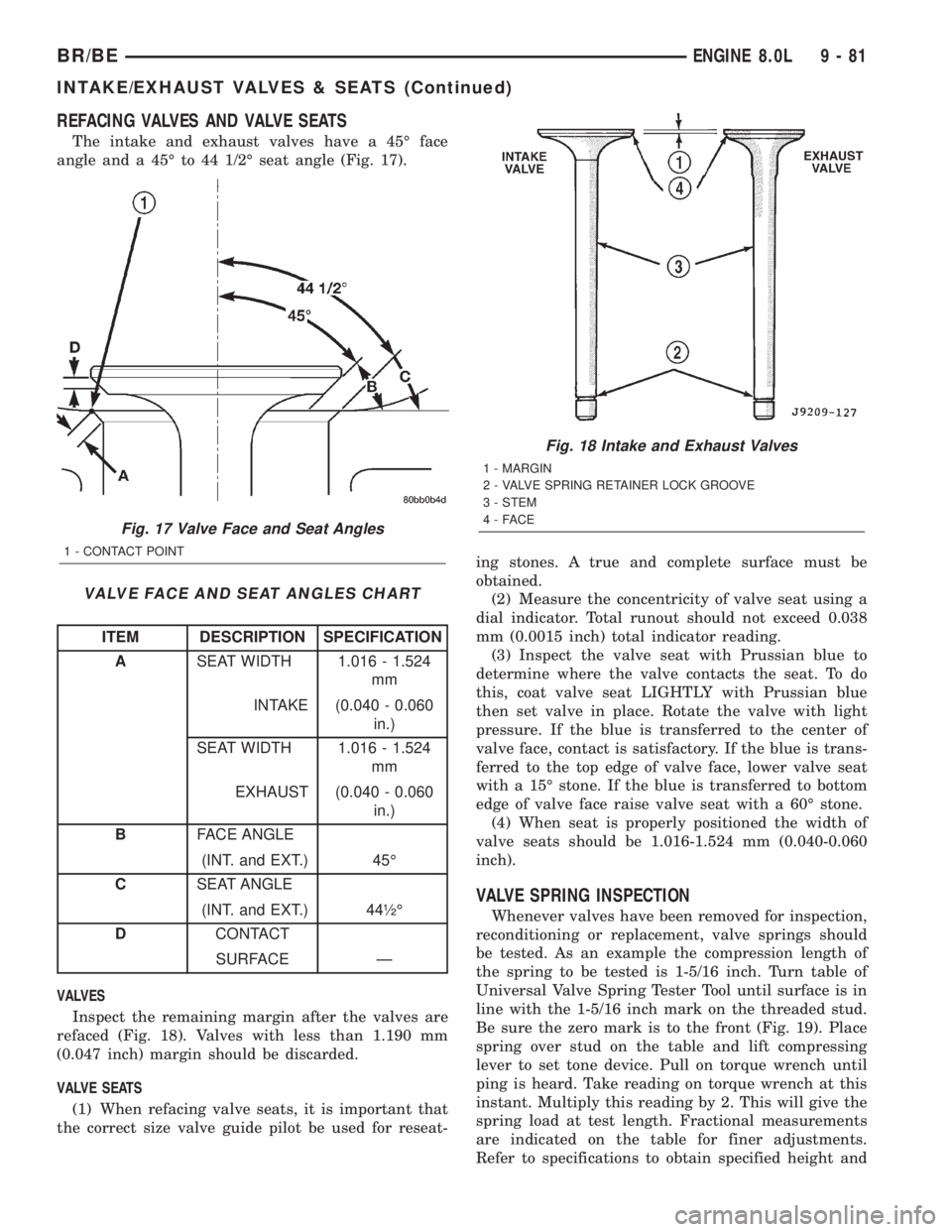
REFACING VALVES AND VALVE SEATS
The intake and exhaust valves have a 45É face
angle and a 45É to 44 1/2É seat angle (Fig. 17).
VALVE FACE AND SEAT ANGLES CHART
ITEM DESCRIPTION SPECIFICATION
ASEAT WIDTH 1.016 - 1.524
mm
INTAKE (0.040 - 0.060
in.)
SEAT WIDTH 1.016 - 1.524
mm
EXHAUST (0.040 - 0.060
in.)
BFACE ANGLE
(INT. and EXT.) 45É
CSEAT ANGLE
(INT. and EXT.) 44óÉ
DCONTACT
SURFACE Ð
VALVES
Inspect the remaining margin after the valves are
refaced (Fig. 18). Valves with less than 1.190 mm
(0.047 inch) margin should be discarded.
VALVE SEATS
(1) When refacing valve seats, it is important that
the correct size valve guide pilot be used for reseat-ing stones. A true and complete surface must be
obtained.
(2) Measure the concentricity of valve seat using a
dial indicator. Total runout should not exceed 0.038
mm (0.0015 inch) total indicator reading.
(3) Inspect the valve seat with Prussian blue to
determine where the valve contacts the seat. To do
this, coat valve seat LIGHTLY with Prussian blue
then set valve in place. Rotate the valve with light
pressure. If the blue is transferred to the center of
valve face, contact is satisfactory. If the blue is trans-
ferred to the top edge of valve face, lower valve seat
with a 15É stone. If the blue is transferred to bottom
edge of valve face raise valve seat with a 60É stone.
(4) When seat is properly positioned the width of
valve seats should be 1.016-1.524 mm (0.040-0.060
inch).
VALVE SPRING INSPECTION
Whenever valves have been removed for inspection,
reconditioning or replacement, valve springs should
be tested. As an example the compression length of
the spring to be tested is 1-5/16 inch. Turn table of
Universal Valve Spring Tester Tool until surface is in
line with the 1-5/16 inch mark on the threaded stud.
Be sure the zero mark is to the front (Fig. 19). Place
spring over stud on the table and lift compressing
lever to set tone device. Pull on torque wrench until
ping is heard. Take reading on torque wrench at this
instant. Multiply this reading by 2. This will give the
spring load at test length. Fractional measurements
are indicated on the table for finer adjustments.
Refer to specifications to obtain specified height and
Fig. 17 Valve Face and Seat Angles
1 - CONTACT POINT
Fig. 18 Intake and Exhaust Valves
1 - MARGIN
2 - VALVE SPRING RETAINER LOCK GROOVE
3 - STEM
4-FACE
BR/BEENGINE 8.0L 9 - 81
INTAKE/EXHAUST VALVES & SEATS (Continued)