2002 DODGE RAM height
[x] Cancel search: heightPage 1339 of 2255

CAUTION: Before tightening sensor mounting bolt,
be sure sensor is completely flush to cylinder block
(Fig. 28). If sensor is not flush, damage to sensor
mounting tang may result.
(3) Install mounting bolt and tighten to 8 N´m (70
in. lbs.) torque.
(4) Connect sensor pigtail harness to main engine
wiring harness
(5) Install new plastic tie strap (Fig. 27) to secure
sensor pigtail harness to side of engine block. Thread
tie strap through casting hole on cylinder block.
FUEL PUMP RELAY
DESCRIPTION
The 5±pin, 12±volt, fuel pump relay is located in
the Power Distribution Center (PDC). Refer to the
label on the PDC cover for relay location.
OPERATION
The Powertrain Control Module (PCM) energizes
the electric fuel pump through the fuel pump relay.
The fuel pump relay is energized by first applying
battery voltage to it when the ignition key is turned
ON, and then applying a ground signal to the relay
from the PCM.
Whenever the ignition key is turned ON, the elec-
tric fuel pump will operate. But, the PCM will shut-
down the ground circuit to the fuel pump relay in
approximately 1±3 seconds unless the engine is oper-
ating or the starter motor is engaged.
REMOVAL
The fuel pump relay is located in the Power Distri-
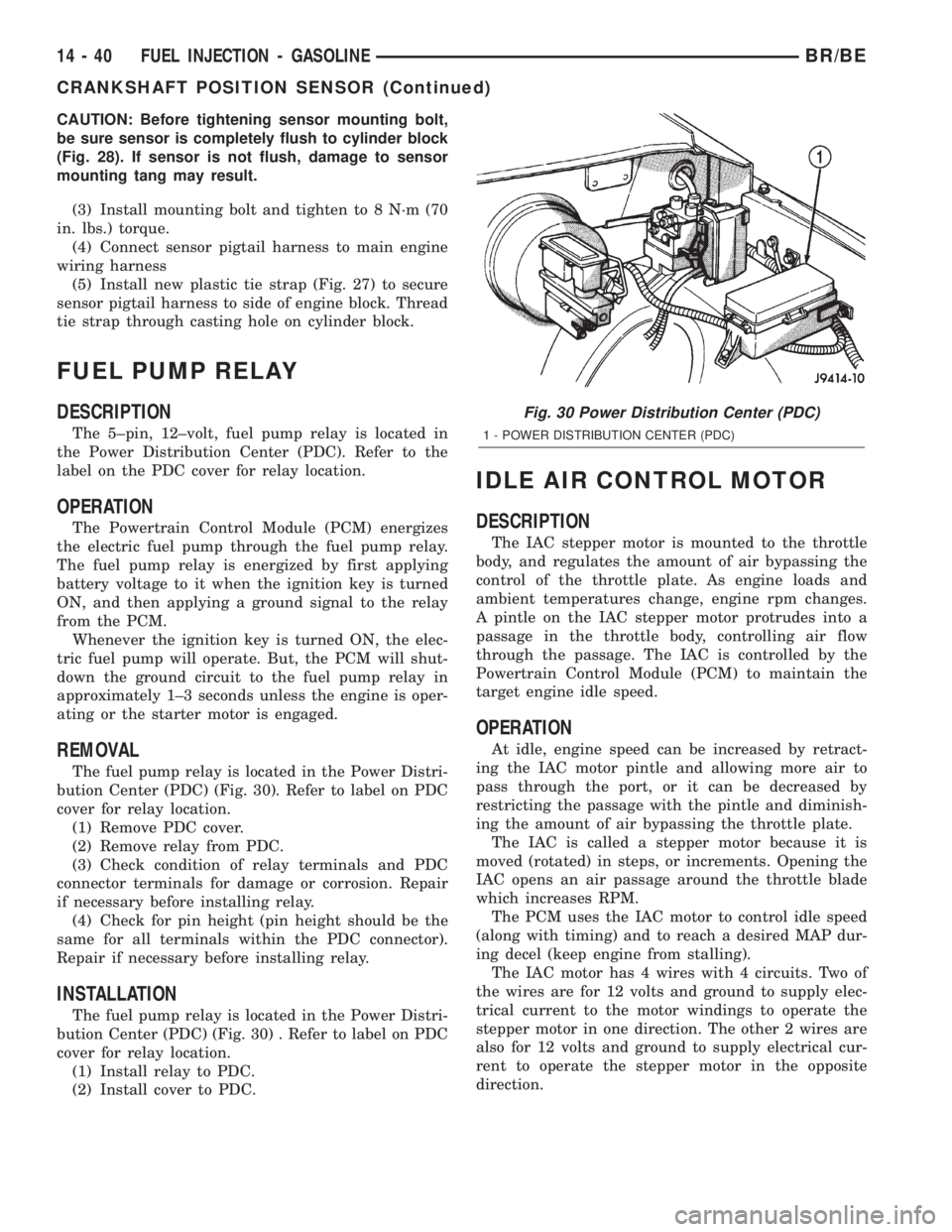
bution Center (PDC) (Fig. 30). Refer to label on PDC
cover for relay location.
(1) Remove PDC cover.
(2) Remove relay from PDC.
(3) Check condition of relay terminals and PDC
connector terminals for damage or corrosion. Repair
if necessary before installing relay.
(4) Check for pin height (pin height should be the
same for all terminals within the PDC connector).
Repair if necessary before installing relay.
INSTALLATION
The fuel pump relay is located in the Power Distri-
bution Center (PDC) (Fig. 30) . Refer to label on PDC
cover for relay location.
(1) Install relay to PDC.
(2) Install cover to PDC.
IDLE AIR CONTROL MOTOR
DESCRIPTION
The IAC stepper motor is mounted to the throttle
body, and regulates the amount of air bypassing the
control of the throttle plate. As engine loads and
ambient temperatures change, engine rpm changes.
A pintle on the IAC stepper motor protrudes into a
passage in the throttle body, controlling air flow
through the passage. The IAC is controlled by the
Powertrain Control Module (PCM) to maintain the
target engine idle speed.
OPERATION
At idle, engine speed can be increased by retract-
ing the IAC motor pintle and allowing more air to
pass through the port, or it can be decreased by
restricting the passage with the pintle and diminish-
ing the amount of air bypassing the throttle plate.
The IAC is called a stepper motor because it is
moved (rotated) in steps, or increments. Opening the
IAC opens an air passage around the throttle blade
which increases RPM.
The PCM uses the IAC motor to control idle speed
(along with timing) and to reach a desired MAP dur-
ing decel (keep engine from stalling).
The IAC motor has 4 wires with 4 circuits. Two of
the wires are for 12 volts and ground to supply elec-
trical current to the motor windings to operate the
stepper motor in one direction. The other 2 wires are
also for 12 volts and ground to supply electrical cur-
rent to operate the stepper motor in the opposite
direction.
Fig. 30 Power Distribution Center (PDC)
1 - POWER DISTRIBUTION CENTER (PDC)
14 - 40 FUEL INJECTION - GASOLINEBR/BE
CRANKSHAFT POSITION SENSOR (Continued)
Page 1368 of 2255

(7) Attach the other jumper wire (12V +) to termi-
nal number 86. This will activate the relay. Continu-
ity should now be present between terminals number
87 and 30. Continuity should not be present between
terminals number 87A and 30.
(8) Disconnect jumper wires from relay and 12 Volt
power source.
(9) If continuity or resistance tests did not pass,
replace relay. If tests passed, refer to 8, Wiring Dia-
grams for (fuel system) relay wiring schematics and
for additional circuit information.
REMOVAL
The fuel heater relay is located in the Power Dis-
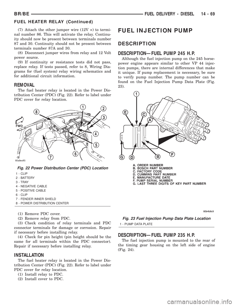
tribution Center (PDC) (Fig. 22). Refer to label under
PDC cover for relay location.
(1) Remove PDC cover.
(2) Remove relay from PDC.
(3) Check condition of relay terminals and PDC
connector terminals for damage or corrosion. Repair
if necessary before installing relay.
(4) Check for pin height (pin height should be the
same for all terminals within the PDC connector).
Repair if necessary before installing relay.
INSTALLATION
The fuel heater relay is located in the Power Dis-
tribution Center (PDC) (Fig. 22). Refer to label under
PDC cover for relay location.
(1) Install relay to PDC.
(2) Install cover to PDC.
FUEL INJECTION PUMP
DESCRIPTION
DESCRIPTIONÐFUEL PUMP 245 H.P.
Although the fuel injection pump on the 245 horse-
power engine appears similar to other VP 44 injec-
tion pumps, there are internal differences that make
it unique. If pump replacement is necessary, be sure
to verify pump number. The pump number can be
found on the Fuel Injection Pump Data Plate (Fig.
23).
DESCRIPTIONÐFUEL PUMP 235 H.P.
The fuel injection pump is mounted to the rear of
the timing gear housing on the left side of engine
(Fig. 24).
Fig. 22 Power Distribution Center (PDC) Location
1 - CLIP
2 - BATTERY
3 - TRAY
4 - NEGATIVE CABLE
5 - POSITIVE CABLE
6 - CLIP
7 - FENDER INNER SHIELD
8 - POWER DISTRIBUTION CENTER
Fig. 23 Fuel Injection Pump Data Plate Location
1 - PUMP DATA PLATE
BR/BEFUEL DELIVERY - DIESEL 14 - 69
FUEL HEATER RELAY (Continued)
Page 1530 of 2255

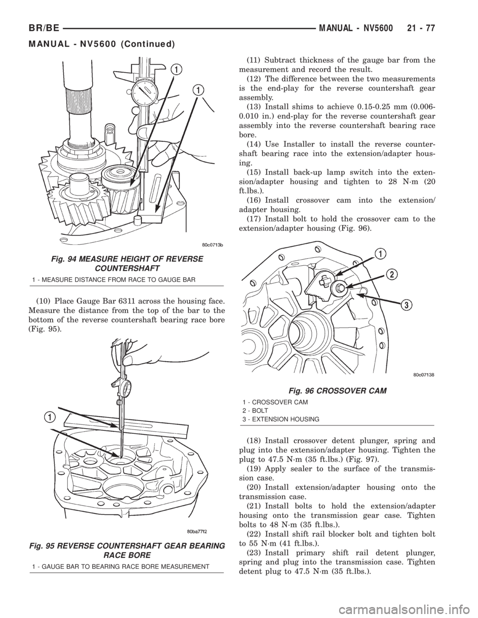
(10) Place Gauge Bar 6311 across the housing face.
Measure the distance from the top of the bar to the
bottom of the reverse countershaft bearing race bore
(Fig. 95).(11) Subtract thickness of the gauge bar from the
measurement and record the result.
(12) The difference between the two measurements
is the end-play for the reverse countershaft gear
assembly.
(13) Install shims to achieve 0.15-0.25 mm (0.006-
0.010 in.) end-play for the reverse countershaft gear
assembly into the reverse countershaft bearing race
bore.
(14) Use Installer to install the reverse counter-
shaft bearing race into the extension/adapter hous-
ing.
(15) Install back-up lamp switch into the exten-
sion/adapter housing and tighten to 28 N´m (20
ft.lbs.).
(16) Install crossover cam into the extension/
adapter housing.
(17) Install bolt to hold the crossover cam to the
extension/adapter housing (Fig. 96).
(18) Install crossover detent plunger, spring and
plug into the extension/adapter housing. Tighten the
plug to 47.5 N´m (35 ft.lbs.) (Fig. 97).
(19) Apply sealer to the surface of the transmis-
sion case.
(20) Install extension/adapter housing onto the
transmission case.
(21) Install bolts to hold the extension/adapter
housing onto the transmission gear case. Tighten
bolts to 48 N´m (35 ft.lbs.).
(22) Install shift rail blocker bolt and tighten bolt
to 55 N´m (41 ft.lbs.).
(23) Install primary shift rail detent plunger,
spring and plug into the transmission case. Tighten
detent plug to 47.5 N´m (35 ft.lbs.).
Fig. 94 MEASURE HEIGHT OF REVERSE
COUNTERSHAFT
1 - MEASURE DISTANCE FROM RACE TO GAUGE BAR
Fig. 95 REVERSE COUNTERSHAFT GEAR BEARING
RACE BORE
1 - GAUGE BAR TO BEARING RACE BORE MEASUREMENT
Fig. 96 CROSSOVER CAM
1 - CROSSOVER CAM
2 - BOLT
3 - EXTENSION HOUSING
BR/BEMANUAL - NV5600 21 - 77
MANUAL - NV5600 (Continued)
Page 2115 of 2255

INSTALLATION
WARNING: Allow the urethane at least 24 hours to
cure before returning the vehicle to use.
CAUTION: Roll down the left and right front door
glass and open the rear glass slider (if available)
before installing windshield to avoid pressurizing
the passenger compartment if a door is slammed
before urethane is cured. Water leaks can result.
The windshield fence should be cleaned of most of its
old urethane bonding material. A small amount of old
urethane, approximately 1-2 mm in height, shouldremain on the fence. Do not grind off or completely
remove all old urethane from the fence, the paint finish
and bonding strength will be adversely affected.
(1) Place replacement windshield into windshield
opening and position glass in the center of the open-
ing against the support spacers. Mark the outside
surface of the glass at the support spacers with a
grease pencil or pieces of masking tape and ink pen
to use as a reference for installation. Remove replace-
ment windshield from windshield opening (Fig. 9).
(2) Position the windshield inside up on a suitable
work surface with two padded, wood 10 cm by 10 cm
by 50 cm (4 in. by 4 in. by 20 in.) blocks, placed par-
allel 75 cm (2.5 ft.) apart (Fig. 10).
(3) Clean inside of windshield with MOPAR Glass
Cleaner and lint-free cloth.
(4) Apply clear glass primer 25 mm (1 in.) wide
around perimeter of windshield and wipe with a new
clean and dry lint- free cloth.
(5) Apply the molding to the windshield:
(a) Press the upper corners of the molding onto
the windshield.
(b) Press the header section onto the windshield.
(c)
Press the A-Pillar sections onto the windshield.
(6) Apply black-out primer onto the glass using the
windshield molding as a guide. The primer should be
15 mm (5/8 in.) wide on the top and sides of the glass
and 25 mm (1 in.) on the bottom of windshield. Allow
at least three minutes drying time.
(7) Locatenewsupport spacers on support brack-
ets and adjust to lowest height.
(8)
Position one 5 mm (3/16 in.) soft spacer (p/n
55028214) at the bottom of the windshield fence (Fig. 11).
(9) Apply a 13mm (1/2 in.) high and 10mm (3/8 in.)
wide bead of urethane around the perimeter of wind-
shield. At the bottom, apply the bead 7 mm (1/4 in.)
inboard from the glass edge. On the three sides
where the molding is on the glass, follow the edge of
molding. The urethane bead should be shaped in a
triangular cross-section, this can be achieved by
notching the tip of the applicator (Fig. 12).
(10) With the aid of a helper, position the wind-
shield over the windshield opening. Align the refer-
ence marks at the bottom of the windshield to the
support spacers.
(11)
Slowly lower windshield glass to the fence open-
ing guiding the lower corners into proper position.
Beginning at the bottom and continuing to the top, push
glass onto fence along the A-Pillars. Push windshield
inward to the fence at the bottom corners (Fig. 13).
(12) Push windshield upward, snug with roof and
ratchet up the adjustable support brackets. Discard
tab from support spacer.
(13) Using clean water, lightly mist the support
spacers.
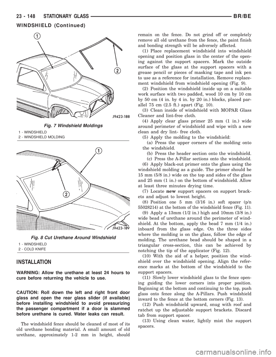
Fig. 7 Windshield Moldings
1 - WINDSHIELD
2 - WINDSHIELD MOLDING
Fig. 8 Cut Urethane Around Windshield
1 - WINDSHIELD
2 - COLD KNIFE
23 - 148 STATIONARY GLASSBR/BE
WINDSHIELD (Continued)