2002 DODGE RAM height
[x] Cancel search: heightPage 1101 of 2255
valve guides. Identify valves to ensure installation in
original location.
CLEANING
Clean valves thoroughly. Discard burned, warped,
or cracked valves.
Remove carbon and varnish deposits from inside of
valve guides with a reliable guide cleaner.
INSPECTION
Measure valve stems for wear. If wear exceeds
0.051 mm (0.002 in.), replace the valve.
Measure valve stem guide clearance as follows:
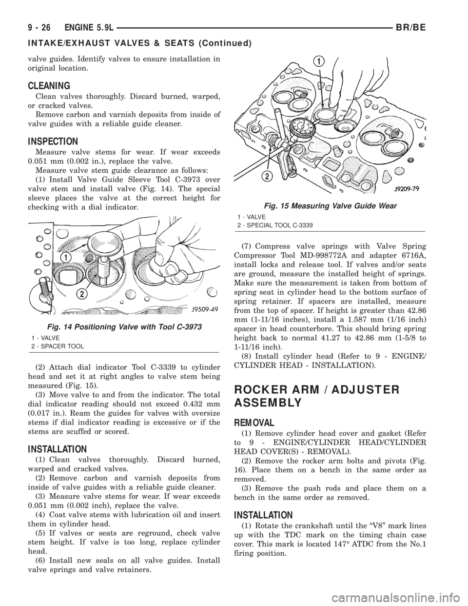
(1) Install Valve Guide Sleeve Tool C-3973 over
valve stem and install valve (Fig. 14). The special
sleeve places the valve at the correct height for
checking with a dial indicator.
(2) Attach dial indicator Tool C-3339 to cylinder
head and set it at right angles to valve stem being
measured (Fig. 15).
(3) Move valve to and from the indicator. The total
dial indicator reading should not exceed 0.432 mm
(0.017 in.). Ream the guides for valves with oversize
stems if dial indicator reading is excessive or if the
stems are scuffed or scored.
INSTALLATION
(1) Clean valves thoroughly. Discard burned,
warped and cracked valves.
(2) Remove carbon and varnish deposits from
inside of valve guides with a reliable guide cleaner.
(3) Measure valve stems for wear. If wear exceeds
0.051 mm (0.002 inch), replace the valve.
(4) Coat valve stems with lubrication oil and insert
them in cylinder head.
(5) If valves or seats are reground, check valve
stem height. If valve is too long, replace cylinder
head.
(6) Install new seals on all valve guides. Install
valve springs and valve retainers.(7) Compress valve springs with Valve Spring
Compressor Tool MD-998772A and adapter 6716A,
install locks and release tool. If valves and/or seats
are ground, measure the installed height of springs.
Make sure the measurement is taken from bottom of
spring seat in cylinder head to the bottom surface of
spring retainer. If spacers are installed, measure
from the top of spacer. If height is greater than 42.86
mm (1-11/16 inches), install a 1.587 mm (1/16 inch)
spacer in head counterbore. This should bring spring
height back to normal 41.27 to 42.86 mm (1-5/8 to
1-11/16 inch).
(8) Install cylinder head (Refer to 9 - ENGINE/
CYLINDER HEAD - INSTALLATION).
ROCKER ARM / ADJUSTER
ASSEMBLY
REMOVAL
(1) Remove cylinder head cover and gasket (Refer
to 9 - ENGINE/CYLINDER HEAD/CYLINDER
HEAD COVER(S) - REMOVAL).
(2) Remove the rocker arm bolts and pivots (Fig.
16). Place them on a bench in the same order as
removed.
(3) Remove the push rods and place them on a
bench in the same order as removed.
INSTALLATION
(1) Rotate the crankshaft until the ªV8º mark lines
up with the TDC mark on the timing chain case
cover. This mark is located 147É ATDC from the No.1
firing position.
Fig. 14 Positioning Valve with Tool C-3973
1 - VALVE
2 - SPACER TOOL
Fig. 15 Measuring Valve Guide Wear
1 - VALVE
2 - SPECIAL TOOL C-3339
9 - 26 ENGINE 5.9LBR/BE
INTAKE/EXHAUST VALVES & SEATS (Continued)
Page 1113 of 2255
(8) Start and operate engine. Warm up to normal
operating temperature.
CAUTION: To prevent damage to valve mechanism,
engine must not be run above fast idle until all
hydraulic tappets have filled with oil and have
become quiet.
PISTON & CONNECTING ROD
DESCRIPTION
The pistons are made of aluminum and have three
ring grooves, the top two grooves are for the compres-
sion rings and the bottom groove is for the oil control
ring. The connecting rods are forged steel and are
coined prior to heat treat. The piston pins are press
fit.
STANDARD PROCEDURE - PISTON FITTING
Piston and cylinder wall must be clean and dry.
Specified clearance between the piston and the cylin-
der wall is 0.013-0.038 mm (0.0005-0.0015 inch) at
21ÉC (70ÉF).
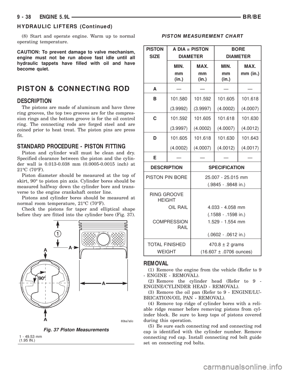
Piston diameter should be measured at the top of
skirt, 90É to piston pin axis. Cylinder bores should be
measured halfway down the cylinder bore and trans-
verse to the engine crankshaft center line.
Pistons and cylinder bores should be measured at
normal room temperature, 21ÉC (70ÉF).
Check the pistons for taper and elliptical shape
before they are fitted into the cylinder bore (Fig. 37).
PISTON MEASUREMENT CHART
PISTON A DIA = PISTON BORE
SIZE DIAMETER DIAMETER
MIN. MAX. MIN. MAX.
mm
(in.)mm
(in.)mm
(in.)mm (in.)
AÐÐÐ Ð
B101.580 101.592 101.605 101.618
(3.9992) (3.9997) (4.0002) (4.0007)
C101.592 101.605 101.618 101.630
(3.9997) (4.0002) (4.0007) (4.0012)
D101.605 101.618 101.630 101.643
(4.0002) (4.0007) (4.0012) (4.0017)
EÐÐÐ Ð
DESCRIPTION SPECIFICATION
PISTON PIN BORE 25.007 - 25.015 mm
(.9845 - .9848 in.)
RING GROOVE
HEIGHT
OIL RAIL 4.033 - 4.058 mm
(.1588 - .1598 in.)
COMPRESSION
RAIL1.529 - 1.554 mm
(.0602 - .0612 in.)
TOTAL FINISHED 470.8 2 grams
WEIGHT (16.607 .0706 ounces)
REMOVAL
(1) Remove the engine from the vehicle (Refer to 9
- ENGINE - REMOVAL).
(2) Remove the cylinder head (Refer to 9 -
ENGINE/CYLINDER HEAD - REMOVAL).
(3) Remove the oil pan (Refer to 9 - ENGINE/LU-
BRICATION/OIL PAN - REMOVAL).
(4) Remove top ridge of cylinder bores with a reli-
able ridge reamer before removing pistons from cyl-
inder block. Be sure to keep tops of pistons covered
during this operation.
(5) Be sure each connecting rod and connecting rod
cap is identified with the cylinder number. Remove
connecting rod cap. Install connecting rod bolt guide
set on connecting rod bolts.
Fig. 37 Piston Measurements
1 - 49.53 mm
(1.95 IN.)
9 - 38 ENGINE 5.9LBR/BE
HYDRAULIC LIFTERS (Continued)
Page 1145 of 2255
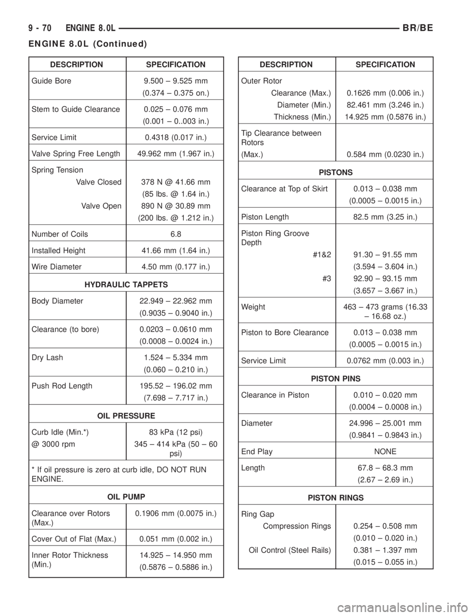
DESCRIPTION SPECIFICATION
Guide Bore 9.500 ± 9.525 mm
(0.374 ± 0.375 on.)
Stem to Guide Clearance 0.025 ± 0.076 mm
(0.001 ± 0..003 in.)
Service Limit 0.4318 (0.017 in.)
Valve Spring Free Length 49.962 mm (1.967 in.)
Spring Tension
Valve Closed 378 N @ 41.66 mm
(85 lbs. @ 1.64 in.)
Valve Open 890 N @ 30.89 mm
(200 lbs. @ 1.212 in.)
Number of Coils 6.8
Installed Height 41.66 mm (1.64 in.)
Wire Diameter 4.50 mm (0.177 in.)
HYDRAULIC TAPPETS
Body Diameter 22.949 ± 22.962 mm
(0.9035 ± 0.9040 in.)
Clearance (to bore) 0.0203 ± 0.0610 mm
(0.0008 ± 0.0024 in.)
Dry Lash 1.524 ± 5.334 mm
(0.060 ± 0.210 in.)
Push Rod Length 195.52 ± 196.02 mm
(7.698 ± 7.717 in.)
OIL PRESSURE
Curb Idle (Min.*) 83 kPa (12 psi)
@ 3000 rpm 345 ± 414 kPa (50 ± 60
psi)
* If oil pressure is zero at curb idle, DO NOT RUN
ENGINE.
OIL PUMP
Clearance over Rotors
(Max.)0.1906 mm (0.0075 in.)
Cover Out of Flat (Max.) 0.051 mm (0.002 in.)
Inner Rotor Thickness
(Min.)14.925 ± 14.950 mm
(0.5876 ± 0.5886 in.)DESCRIPTION SPECIFICATION
Outer Rotor
Clearance (Max.) 0.1626 mm (0.006 in.)
Diameter (Min.) 82.461 mm (3.246 in.)
Thickness (Min.) 14.925 mm (0.5876 in.)
Tip Clearance between
Rotors
(Max.) 0.584 mm (0.0230 in.)
PISTONS
Clearance at Top of Skirt 0.013 ± 0.038 mm
(0.0005 ± 0.0015 in.)
Piston Length 82.5 mm (3.25 in.)
Piston Ring Groove
Depth
#1&2 91.30 ± 91.55 mm
(3.594 ± 3.604 in.)
#3 92.90 ± 93.15 mm
(3.657 ± 3.667 in.)
Weight 463 ± 473 grams (16.33
± 16.68 oz.)
Piston to Bore Clearance 0.013 ± 0.038 mm
(0.0005 ± 0.0015 in.)
Service Limit 0.0762 mm (0.003 in.)
PISTON PINS
Clearance in Piston 0.010 ± 0.020 mm
(0.0004 ± 0.0008 in.)
Diameter 24.996 ± 25.001 mm
(0.9841 ± 0.9843 in.)
End Play NONE
Length 67.8 ± 68.3 mm
(2.67 ± 2.69 in.)
PISTON RINGS
Ring Gap
Compression Rings 0.254 ± 0.508 mm
(0.010 ± 0.020 in.)
Oil Control (Steel Rails) 0.381 ± 1.397 mm
(0.015 ± 0.055 in.)
9 - 70 ENGINE 8.0LBR/BE
ENGINE 8.0L (Continued)
Page 1155 of 2255
INTAKE/EXHAUST VALVES &
SEATS
DESCRIPTION
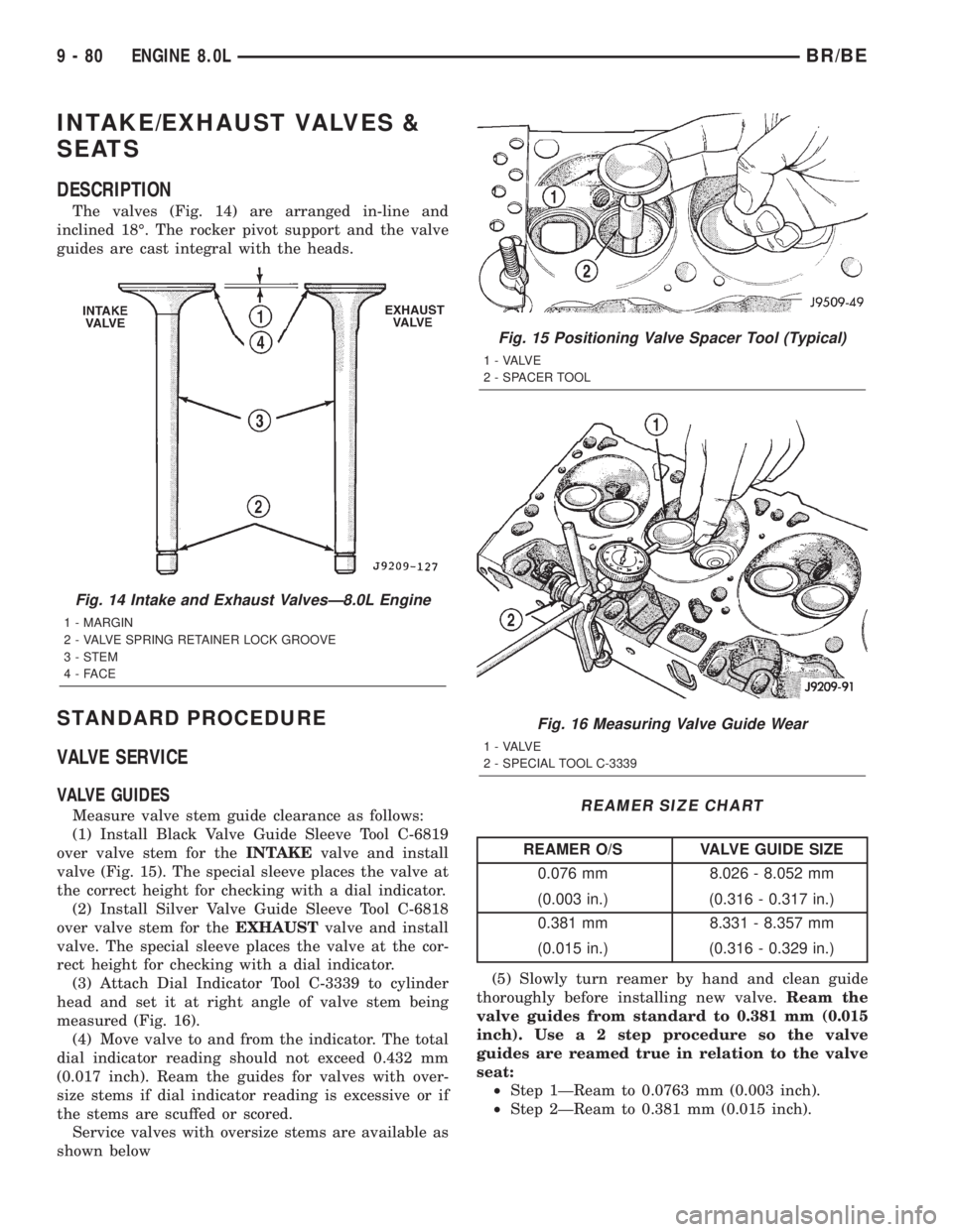
The valves (Fig. 14) are arranged in-line and
inclined 18É. The rocker pivot support and the valve
guides are cast integral with the heads.
STANDARD PROCEDURE
VALVE SERVICE
VALVE GUIDES
Measure valve stem guide clearance as follows:
(1) Install Black Valve Guide Sleeve Tool C-6819
over valve stem for theINTAKEvalve and install
valve (Fig. 15). The special sleeve places the valve at
the correct height for checking with a dial indicator.
(2) Install Silver Valve Guide Sleeve Tool C-6818
over valve stem for theEXHAUSTvalve and install
valve. The special sleeve places the valve at the cor-
rect height for checking with a dial indicator.
(3) Attach Dial Indicator Tool C-3339 to cylinder
head and set it at right angle of valve stem being
measured (Fig. 16).
(4) Move valve to and from the indicator. The total
dial indicator reading should not exceed 0.432 mm
(0.017 inch). Ream the guides for valves with over-
size stems if dial indicator reading is excessive or if
the stems are scuffed or scored.
Service valves with oversize stems are available as
shown belowREAMER SIZE CHART
REAMER O/S VALVE GUIDE SIZE
0.076 mm 8.026 - 8.052 mm
(0.003 in.) (0.316 - 0.317 in.)
0.381 mm 8.331 - 8.357 mm
(0.015 in.) (0.316 - 0.329 in.)
(5) Slowly turn reamer by hand and clean guide
thoroughly before installing new valve.Ream the
valve guides from standard to 0.381 mm (0.015
inch). Use a 2 step procedure so the valve
guides are reamed true in relation to the valve
seat:
²Step 1ÐReam to 0.0763 mm (0.003 inch).
²Step 2ÐReam to 0.381 mm (0.015 inch).
Fig. 14 Intake and Exhaust ValvesÐ8.0L Engine
1 - MARGIN
2 - VALVE SPRING RETAINER LOCK GROOVE
3 - STEM
4-FACE
Fig. 15 Positioning Valve Spacer Tool (Typical)
1 - VALVE
2 - SPACER TOOL
Fig. 16 Measuring Valve Guide Wear
1 - VALVE
2 - SPECIAL TOOL C-3339
9 - 80 ENGINE 8.0LBR/BE
Page 1156 of 2255
REFACING VALVES AND VALVE SEATS
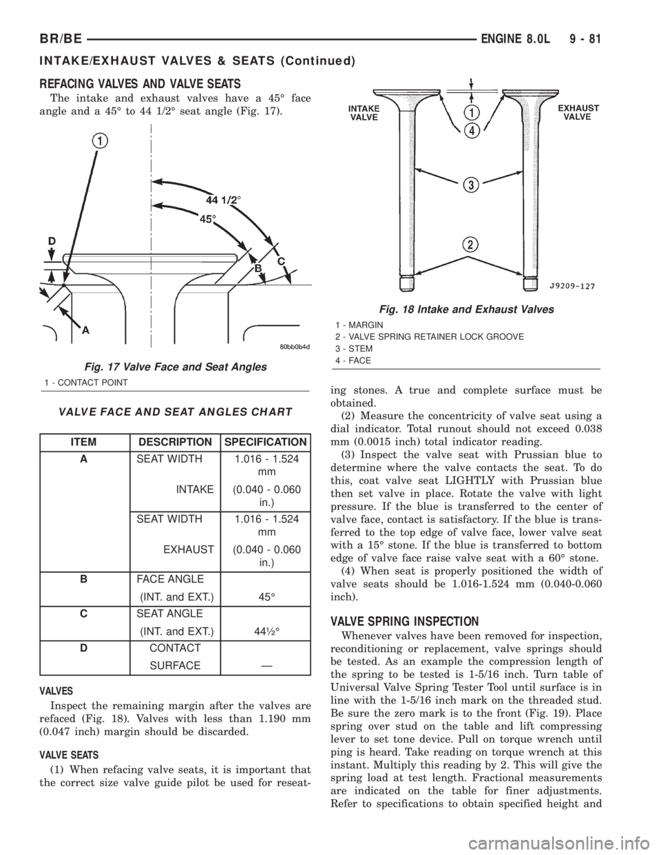
The intake and exhaust valves have a 45É face
angle and a 45É to 44 1/2É seat angle (Fig. 17).
VALVE FACE AND SEAT ANGLES CHART
ITEM DESCRIPTION SPECIFICATION
ASEAT WIDTH 1.016 - 1.524
mm
INTAKE (0.040 - 0.060
in.)
SEAT WIDTH 1.016 - 1.524
mm
EXHAUST (0.040 - 0.060
in.)
BFACE ANGLE
(INT. and EXT.) 45É
CSEAT ANGLE
(INT. and EXT.) 44óÉ
DCONTACT
SURFACE Ð
VALVES
Inspect the remaining margin after the valves are
refaced (Fig. 18). Valves with less than 1.190 mm
(0.047 inch) margin should be discarded.
VALVE SEATS
(1) When refacing valve seats, it is important that
the correct size valve guide pilot be used for reseat-ing stones. A true and complete surface must be
obtained.
(2) Measure the concentricity of valve seat using a
dial indicator. Total runout should not exceed 0.038
mm (0.0015 inch) total indicator reading.
(3) Inspect the valve seat with Prussian blue to
determine where the valve contacts the seat. To do
this, coat valve seat LIGHTLY with Prussian blue
then set valve in place. Rotate the valve with light
pressure. If the blue is transferred to the center of
valve face, contact is satisfactory. If the blue is trans-
ferred to the top edge of valve face, lower valve seat
with a 15É stone. If the blue is transferred to bottom
edge of valve face raise valve seat with a 60É stone.
(4) When seat is properly positioned the width of
valve seats should be 1.016-1.524 mm (0.040-0.060
inch).
VALVE SPRING INSPECTION
Whenever valves have been removed for inspection,
reconditioning or replacement, valve springs should
be tested. As an example the compression length of
the spring to be tested is 1-5/16 inch. Turn table of
Universal Valve Spring Tester Tool until surface is in
line with the 1-5/16 inch mark on the threaded stud.
Be sure the zero mark is to the front (Fig. 19). Place
spring over stud on the table and lift compressing
lever to set tone device. Pull on torque wrench until
ping is heard. Take reading on torque wrench at this
instant. Multiply this reading by 2. This will give the
spring load at test length. Fractional measurements
are indicated on the table for finer adjustments.
Refer to specifications to obtain specified height and
Fig. 17 Valve Face and Seat Angles
1 - CONTACT POINT
Fig. 18 Intake and Exhaust Valves
1 - MARGIN
2 - VALVE SPRING RETAINER LOCK GROOVE
3 - STEM
4-FACE
BR/BEENGINE 8.0L 9 - 81
INTAKE/EXHAUST VALVES & SEATS (Continued)
Page 1158 of 2255
(4) Remove valve retaining locks, valve spring
retainers and valve springs. Check for abnormal
wear, replace as required.
(5) Remove the valve stem seals.
(6) Before removing valves, remove any burrs from
valve stem lock grooves to prevent damage to the
valve guides. Identify valves to ensure installation in
original location.
CLEANING
Clean valves thoroughly. Discard burned, warped,
or cracked valves.
Remove carbon and varnish deposits from inside of
valve guides with a reliable guide cleaner.
INSPECTION
Measure valve stems for wear. If wear exceeds
0.051 mm (0.002 in.), replace the valve.
Measure valve stem guide clearance as follows:
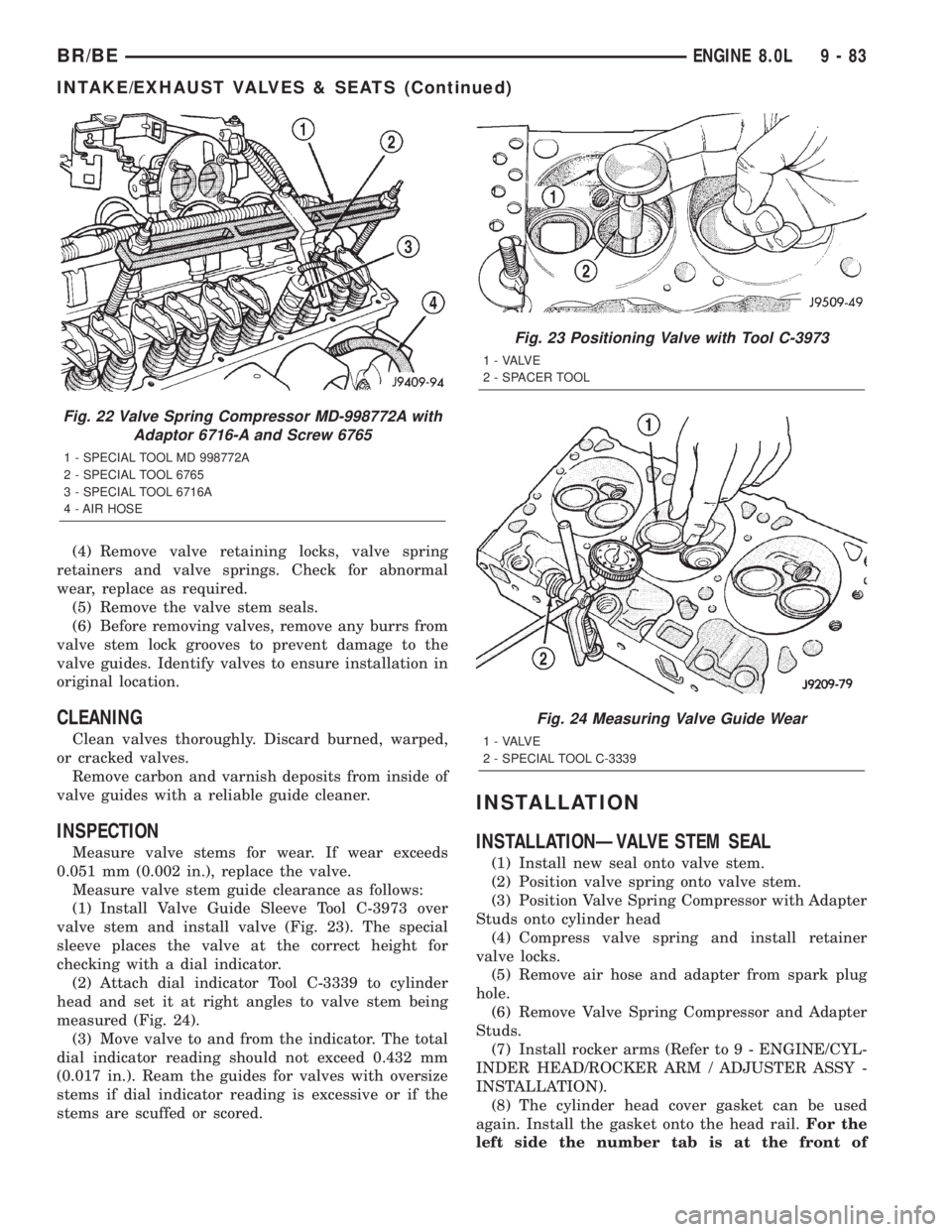
(1) Install Valve Guide Sleeve Tool C-3973 over
valve stem and install valve (Fig. 23). The special
sleeve places the valve at the correct height for
checking with a dial indicator.
(2) Attach dial indicator Tool C-3339 to cylinder
head and set it at right angles to valve stem being
measured (Fig. 24).
(3) Move valve to and from the indicator. The total
dial indicator reading should not exceed 0.432 mm
(0.017 in.). Ream the guides for valves with oversize
stems if dial indicator reading is excessive or if the
stems are scuffed or scored.
INSTALLATION
INSTALLATIONÐVALVE STEM SEAL
(1) Install new seal onto valve stem.
(2) Position valve spring onto valve stem.
(3) Position Valve Spring Compressor with Adapter
Studs onto cylinder head
(4) Compress valve spring and install retainer
valve locks.
(5) Remove air hose and adapter from spark plug
hole.
(6) Remove Valve Spring Compressor and Adapter
Studs.
(7) Install rocker arms (Refer to 9 - ENGINE/CYL-
INDER HEAD/ROCKER ARM / ADJUSTER ASSY -
INSTALLATION).
(8) The cylinder head cover gasket can be used
again. Install the gasket onto the head rail.For the
left side the number tab is at the front of
Fig. 22 Valve Spring Compressor MD-998772A with
Adaptor 6716-A and Screw 6765
1 - SPECIAL TOOL MD 998772A
2 - SPECIAL TOOL 6765
3 - SPECIAL TOOL 6716A
4 - AIR HOSE
Fig. 23 Positioning Valve with Tool C-3973
1 - VALVE
2 - SPACER TOOL
Fig. 24 Measuring Valve Guide Wear
1 - VALVE
2 - SPECIAL TOOL C-3339
BR/BEENGINE 8.0L 9 - 83
INTAKE/EXHAUST VALVES & SEATS (Continued)
Page 1159 of 2255
engine with the number up. For the right side
the number tab is at the rear of engine with the
number up.
CAUTION: The cylinder head cover fasteners have a
special plating. DO NOT use alternative fasteners.
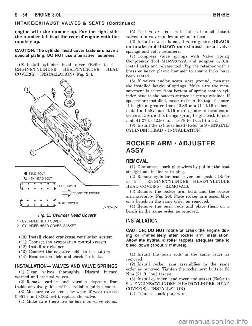
(9) Install cylinder head cover (Refer to 9 -
ENGINE/CYLINDER HEAD/CYLINDER HEAD
COVER(S) - INSTALLATION) (Fig. 25).
(10) Install closed crankcase ventilation system.
(11) Connect the evaporation control system.
(12) Install air cleaner.
(13) Connect the negative cable to the battery.
(14) Road test vehicle and check for leaks.
INSTALLATIONÐVALVES AND VALVE SPRINGS
(1) Clean valves thoroughly. Discard burned,
warped and cracked valves.
(2) Remove carbon and varnish deposits from
inside of valve guides with a reliable guide cleaner.
(3) Measure valve stems for wear. If wear exceeds
0.051 mm (0.002 inch), replace the valve.
(4) Make sure there are no burrs on valve stems.(5) Coat valve stems with lubrication oil. Insert
valves into valve guides in cylinder head.
(6) Install new seals on all valve guides(BLACK
on intake and BROWN on exhaust). Install valve
springs and valve retainers.
(7) Compress valve springs with Valve Spring
Compressor Tool MD-998772A and adapter 6716A,
install locks and release tool. Tap the retainer with a
brass or heavy plastic hammer to ensure locks have
been seated.
(8) If valves and/or seats were ground, measure
the installed height of springs. Make sure the mea-
surement is taken from bottom of spring seat in cyl-
inder head to the bottom surface of spring retainer. If
spacers are installed, measure from the top of spacer.
If height is greater than 42.86 mm (1-11/16 inches),
install a 1.587 mm (1/16 inch) spacer in head coun-
terbore. Ensure this brings spring height back to nor-
mal, 41.27 to 42.86 mm (1-5/8 to 1-11/16 inch).
(9) Install the cylinder head (Refer to 9 - ENGINE/
CYLINDER HEAD - INSTALLATION).
ROCKER ARM / ADJUSTER
ASSY
REMOVAL
(1) Disconnect spark plug wires by pulling the boot
straight out in line with plug.
(2) Remove cylinder head cover and gasket (Refer
to 9 - ENGINE/CYLINDER HEAD/CYLINDER
HEAD COVER(S) - REMOVAL).
(3) Remove the rocker arm bolts and the rocker
arm assembly (Fig. 26). Place rocker arm assemblies
on a bench in the same order as removed.
(4) Remove the push rods and place them on a
bench in the same order as removed.
INSTALLATION
CAUTION: DO NOT rotate or crank the engine dur-
ing or immediately after rocker arm installation.
Allow the hydraulic roller tappets adequate time to
bleed down (about 5 minutes).
(1) Install the push rods in the same order as
removed.
(2) Install rocker arm assemblies in the same
order as removed. Tighten the rocker arm bolts to 28
N´m (21 ft. lbs.) torque.
(3) Install cylinder head cover and gasket (Refer to
9 - ENGINE/CYLINDER HEAD/CYLINDER HEAD
COVER(S) - INSTALLATION).
(4) Connect spark plug wires.
Fig. 25 Cylinder Head Covers
1 - CYLINDER HEAD COVER
2 - CYLINDER HEAD COVER GASKET
9 - 84 ENGINE 8.0LBR/BE
INTAKE/EXHAUST VALVES & SEATS (Continued)
Page 1255 of 2255
INSTALLATION
(1) Fill the T-joint between the pan rail/gear hous-
ing and pan rail/rear seal retainer with sealant. Use
MopartSilicone Rubber Adhesive Sealant or equiva-
lent.
(2) Apply a film of MopartSilicone Rubber Adhe-
sive Sealant or equivalent to the oil pan gasket.
Apply sealant only to the side that faces the oil pan.
(3) Place suction tube in oil pan and guide them
into place (Fig. 151). Using a new tube to oil pump
gasket, install and tighten the suction tube bolts by
hand. Starting with the oil pump inlet bolts, tighten
the bolts to 24 N´m (18 ft. lbs.) torque. Tighten the
remaining tube brace bolts to 24 N´m (18 ft. lbs.)
torque.
(4) Starting in the center and working outward,
tighten the oil pan bolts to 24 N´m (18 ft. lbs.)
torque.
(5) Install the flywheel housing assembly with the
starter motor attached and tighten bolts to 60 N´m
(44 ft. lbs.) torque.
(6) Connect starter motor cables.
(7) Install transmission and transfer case (if
equipped).
(8) Lower vehicle.
(9) Install battery negative cables.
(10) Fill the crankcase with new engine oil.
(11) Start engine and check for leaks. Stop engine,
check oil level, and adjust, if necessary.
OIL PRESSURE RELIEF VALVE
REMOVAL
(1) Disconnect the battery negative cables.
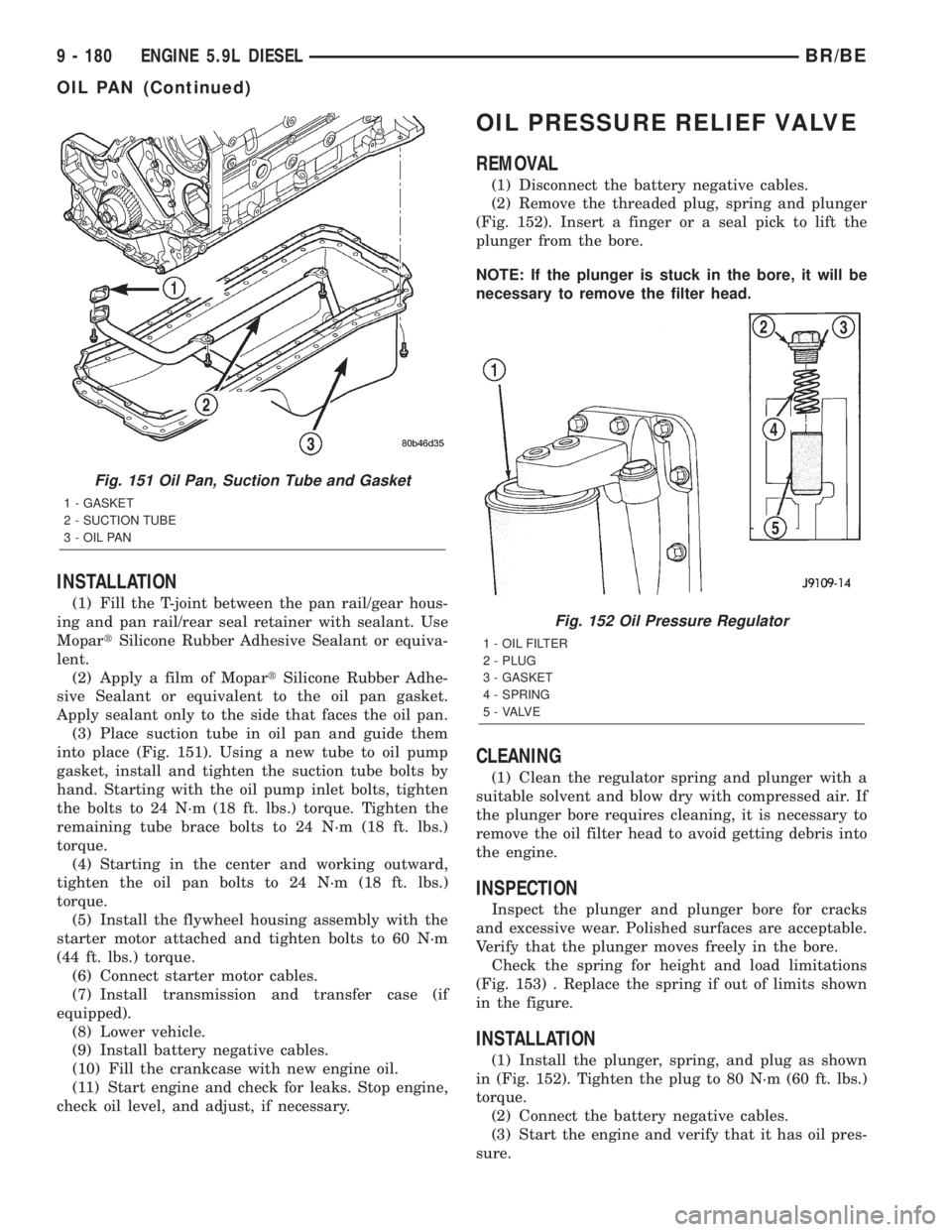
(2) Remove the threaded plug, spring and plunger
(Fig. 152). Insert a finger or a seal pick to lift the
plunger from the bore.
NOTE: If the plunger is stuck in the bore, it will be
necessary to remove the filter head.
CLEANING
(1) Clean the regulator spring and plunger with a
suitable solvent and blow dry with compressed air. If
the plunger bore requires cleaning, it is necessary to
remove the oil filter head to avoid getting debris into
the engine.
INSPECTION
Inspect the plunger and plunger bore for cracks
and excessive wear. Polished surfaces are acceptable.
Verify that the plunger moves freely in the bore.
Check the spring for height and load limitations
(Fig. 153) . Replace the spring if out of limits shown
in the figure.
INSTALLATION
(1) Install the plunger, spring, and plug as shown
in (Fig. 152). Tighten the plug to 80 N´m (60 ft. lbs.)
torque.
(2) Connect the battery negative cables.
(3) Start the engine and verify that it has oil pres-
sure.
Fig. 151 Oil Pan, Suction Tube and Gasket
1 - GASKET
2 - SUCTION TUBE
3 - OIL PAN
Fig. 152 Oil Pressure Regulator
1 - OIL FILTER
2 - PLUG
3 - GASKET
4 - SPRING
5 - VALVE
9 - 180 ENGINE 5.9L DIESELBR/BE
OIL PAN (Continued)