2002 DODGE RAM lubrication
[x] Cancel search: lubricationPage 260 of 2255

CONDITION POSSIBLE CAUSES CORRECTION
COOLANT LOSS TO THE
GROUND WITHOUT PRESSURE
CAP BLOWOFF. GAUGE READING
HIGH OR HOT1. Coolant leaks in radiator, cooling
system hoses, water pump or
engine.1. Pressure test and repair as
necessary. (Refer to 7 - COOLING -
DIAGNOSIS AND TESTING).
DETONATION OR PRE-IGNITION
(NOT CAUSED BY IGNITION
SYSTEM). GAUGE MAY OR MAY
NOT BE READING HIGH1. Engine overheating. 1. Check reason for overheating
and repair as necessary.
2. Freeze point of coolant not
correct. Mixture is too rich or too
lean.2. Check coolant concentration.
(Refer to LUBRICATION &
MAINTENANCE/FLUID TYPES -
DESCRIPTION).
HOSE OR HOSES COLLAPSE
WHILE ENGINE IS RUNNING1. Vacuum created in cooling
system on engine cool-down is not
being relieved through coolant
reserve/overflow system.1. (a) Radiator cap relief valve
stuck. (Refer to 7 - COOLING/
ENGINE/RADIATOR PRESSURE
CAP - DIAGNOSIS AND TESTING).
Replace if necessary
(b) Hose between coolant
reserve/overflow tank and radiator is
kinked. Repair as necessary.
(c) Vent at coolant reserve/overflow
tank is plugged. Clean vent and
repair as necessary.
(d) Reserve/overflow tank is
internally blocked or plugged. Check
for blockage and repair as
necessary.
NOISY VISCOUS FAN/DRIVE 1. Fan blades loose. 1. Replace fan blade assembly.
(Refer to 7 - COOLING/ENGINE/
RADIATOR FAN - REMOVAL)
2. Fan blades striking a surrounding
object.2. Locate point of fan blade contact
and repair as necessary.
3. Air obstructions at radiator or air
conditioning condenser.3. Remove obstructions and/or
clean debris or insects from radiator
or A/C condenser.
4. Thermal viscous fan drive has
defective bearing.4. Replace fan drive. Bearing is not
serviceable. (Refer to 7 - COOLING/
ENGINE/FAN DRIVE VISCOUS
CLUTCH - REMOVAL).
5. A certain amount of fan noise
may be evident on models
equipped with a thermal viscous fan
drive. Some of this noise is normal.5. (Refer to 7 - COOLING/ENGINE/
FAN DRIVE VISCOUS CLUTCH -
DESCRIPTION) for an explanation
of normal fan noise.
BR/BECOOLING 7 - 11
COOLING (Continued)
Page 261 of 2255

CONDITION POSSIBLE CAUSES CORRECTION
INADEQUATE HEATER
PERFORMANCE. THERMOSTAT
FAILED IN OPEN POSITION1. Has a Diagnostic trouble Code
(DTC) been set?1. (Refer to 25 - EMISSIONS
CONTROL - DESCRIPTION) for
correct procedures and replace
thermostat if necessary
2. Coolant level low 2. (Refer to 7 - COOLING -
DIAGNOSIS AND TESTING).
3. Obstructions in heater hose/
fittings3. Remove heater hoses at both
ends and check for obstructions
4. Heater hose kinked 4. Locate kinked area and repair as
necessary
5. Water pump is not pumping
water to/through the heater core.
When the engine is fully warmed
up, both heater hoses should be
hot to the touch. If only one of the
hoses is hot, the water pump may
not be operating correctly or the
heater core may be plugged.
Accessory drive belt may be
slipping causing poor water pump
operation.5. (Refer to 7 - COOLING/ENGINE/
WATER PUMP - REMOVAL). If a
slipping belt is detected, (Refer to 7
- COOLING/ACCESSORY
DRIVE/DRIVE BELTS - DIAGNOSIS
AND TESTING). If heater core
obstruction is detected, (Refer to 24
- HEATING & AIR CONDITIONING/
PLUMBING/HEATER CORE -
REMOVAL).
STEAM IS COMING FROM THE
FRONT OF VEHICLE NEAR THE
GRILL AREA WHEN WEATHER IS
WET, ENGINE IS WARMED UP
AND RUNNING, AND VEHICLE IS
STATIONARY. TEMPERATURE
GAUGE IS IN NORMAL RANGE1. During wet weather, moisture
(snow, ice or rain condensation) on
the radiator will evaporate when the
thermostat opens. This opening
allows heated water into the
radiator. When the moisture
contacts the hot radiator, steam
may be emitted. This usually occurs
in cold weather with no fan or
airflow to blow it away.1. Occasional steam emitting from
this area is normal. No repair is
necessary.
COOLANT COLOR 1. Coolant color is not necessarily
an indication of adequate corrosion
or temperature protection. Do not
rely on coolant color for determining
condition of coolant.1. (Refer to LUBRICATION &
MAINTENANCE/FLUID TYPES -
DESCRIPTION). Adjust coolant
mixture as necessary.
COOLANT LEVEL CHANGES IN
COOLANT RESERVE/OVERFLOW
TANK. TEMPERATURE GAUGE IS
IN NORMAL RANGE1. Level changes are to be
expected as coolant volume
fluctuates with engine temperature.
If the level in the tank was between
the FULL and ADD marks at normal
operating temperature, the level
should return to within that range
after operation at elevated
temperatures.1. A normal condition. No repair is
necessary.
7 - 12 COOLINGBR/BE
COOLING (Continued)
Page 391 of 2255

²Battery- The storage battery provides a reli-
able means of storing a renewable source of electrical
energy within the vehicle.
²Battery Cable- The battery cables connect the
battery terminal posts to the vehicle electrical sys-
tem.
²Battery Holddown- The battery holddown
hardware secures the battery in the battery tray in
the engine compartment.
²Battery Tray- The battery tray provides a
secure mounting location in the vehicle for the bat-
tery and an anchor point for the battery holddown
hardware.
For battery system maintenance schedules and
jump starting procedures, see the owner's manual in
the vehicle glove box. Optionally, refer to Lubrication
and Maintenance for the recommended battery main-
tenance schedules and for the proper battery jump
starting procedures. While battery charging can be
considered a maintenance procedure, the battery
charging procedures and related information are
located in the standard procedures section of this ser-
vice manual. This was done because the battery must
be fully-charged before any battery system diagnosis
or testing procedures can be performed. Refer to
Standard procedures for the proper battery charging
procedures.
OPERATION
The battery system is designed to provide a safe,
efficient, reliable and mobile means of delivering and
storing electrical energy. This electrical energy is
required to operate the engine starting system, as
well as to operate many of the other vehicle acces-
sory systems for limited durations while the engine
and/or the charging system are not operating. The
battery system is also designed to provide a reserve
of electrical energy to supplement the charging sys-
tem for short durations while the engine is running
and the electrical current demands of the vehicle
exceed the output of the charging system. In addition
to delivering, and storing electrical energy for the
vehicle, the battery system serves as a capacitor and
voltage stabilizer for the vehicle electrical system. It
absorbs most abnormal or transient voltages caused
by the switching of any of the electrical components
or circuits in the vehicle.
DIAGNOSIS AND TESTING - BATTERY SYSTEM
The battery, starting, and charging systems in the
vehicle operate with one another and must be tested
as a complete system. In order for the engine to start
and the battery to maintain its charge properly, all of
the components that are used in these systems must
perform within specifications. It is important that
the battery, starting, and charging systems be thor-
oughly tested and inspected any time a battery needs
to be charged or replaced. The cause of abnormal bat-
tery discharge, overcharging or early battery failure
must be diagnosed and corrected before a battery is
replaced and before a vehicle is returned to service.
The service information for these systems has been
separated within this service manual to make it eas-
ier to locate the specific information you are seeking.
However, when attempting to diagnose any of these
systems, it is important that you keep their interde-
pendency in mind.
The diagnostic procedures used for the battery,
starting, and charging systems include the most
basic conventional diagnostic methods, to the more
sophisticated On-Board Diagnostics (OBD) built into
the Powertrain Control Module (PCM). Use of an
induction-type milliampere ammeter, a volt/ohmme-
ter, a battery charger, a carbon pile rheostat (load
tester) and a 12-volt test lamp may be required. All
OBD-sensed systems are monitored by the PCM.
Each monitored circuit is assigned a Diagnostic Trou-
ble Code (DTC). The PCM will store a DTC in elec-
tronic memory for any failure it detects. Refer to
Charging System for the proper charging system on-
board diagnostic test procedures.
MIDTRONICS ELECTRICAL SYSTEM TESTER
The Midtronicstautomotive battery and charging
system tester is designed to help the dealership tech-
nicians diagnose the cause of a defective battery or
charging system. Follow the instruction manual sup-
plied with the tester to properly diagnose a vehicle. If
the instruction manual is not available refer to the
standard procedure in this section, which includes
the directions for using the midtronics electrical sys-
tem tester.
8F - 2 BATTERY SYSTEMBR/BE
BATTERY SYSTEM (Continued)
Page 467 of 2255
(4) Install mounting bolt and tighten to 20 Nm (15
ft. lbs.) torque.
(5) Install electrical connector to CMP.
(6) Connect both negative cables to both batteries.
INSTALLATION - 5.9L
The camshaft position sensor is located in the dis-
tributor (Fig. 11).
(1) Install camshaft position sensor to distributor.
Align sensor into notch on distributor housing.
(2) Connect wiring harness.
(3) Install rotor.
(4) Install distributor cap. Tighten mounting
screws.
(5) Install air cleaner assembly.
INSTALLATION - 8.0L
If Replacing Old Sensor With Original
The camshaft position sensor is located on the tim-
ing chain case/cover on the left-front side of the
engine (Fig. 12).
When installing a used camshaft position sensor,
the sensor depth must be adjusted to prevent contact
with the camshaft gear (sprocket).
(1) Observe the face of the sensor. If any of the
original rib material remains (Fig. 13), it must be cut
down flush to the face of the sensor with a razor
knife. Remove only enough of the rib material until
the face of the sensor is flat. Do not remove more
material than necessary as damage to sensor may
result. Due to a high magnetic field and possible elec-
trical damage to the sensor, never use an electric
grinder to remove material from sensor.
(2) From the parts department, obtain a peel-and-
stick paper spacer (Fig. 13). These special paper
spacers are of a certain thickness and are to be used
as a tool to set sensor depth.
(3) Clean the face of sensor and apply paper
spacer (Fig. 13).
(4) Apply a small amount of engine oil to the sen-
sor o-ring (Fig. 14).
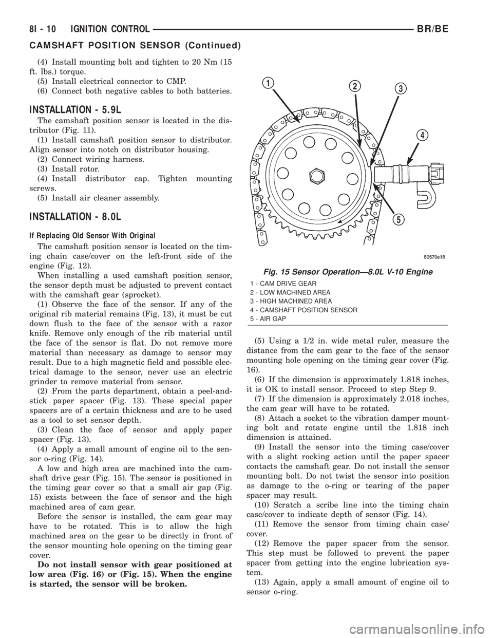
A low and high area are machined into the cam-
shaft drive gear (Fig. 15). The sensor is positioned in
the timing gear cover so that a small air gap (Fig.
15) exists between the face of sensor and the high
machined area of cam gear.
Before the sensor is installed, the cam gear may
have to be rotated. This is to allow the high
machined area on the gear to be directly in front of
the sensor mounting hole opening on the timing gear
cover.
Do not install sensor with gear positioned at
low area (Fig. 16) or (Fig. 15). When the engine
is started, the sensor will be broken.(5) Using a 1/2 in. wide metal ruler, measure the
distance from the cam gear to the face of the sensor
mounting hole opening on the timing gear cover (Fig.
16).
(6) If the dimension is approximately 1.818 inches,
it is OK to install sensor. Proceed to step Step 9.
(7) If the dimension is approximately 2.018 inches,
the cam gear will have to be rotated.
(8) Attach a socket to the vibration damper mount-
ing bolt and rotate engine until the 1.818 inch
dimension is attained.
(9) Install the sensor into the timing case/cover
with a slight rocking action until the paper spacer
contacts the camshaft gear. Do not install the sensor
mounting bolt. Do not twist the sensor into position
as damage to the o-ring or tearing of the paper
spacer may result.
(10) Scratch a scribe line into the timing chain
case/cover to indicate depth of sensor (Fig. 14).
(11) Remove the sensor from timing chain case/
cover.
(12) Remove the paper spacer from the sensor.
This step must be followed to prevent the paper
spacer from getting into the engine lubrication sys-
tem.
(13) Again, apply a small amount of engine oil to
sensor o-ring.
Fig. 15 Sensor OperationÐ8.0L V-10 Engine
1 - CAM DRIVE GEAR
2 - LOW MACHINED AREA
3 - HIGH MACHINED AREA
4 - CAMSHAFT POSITION SENSOR
5 - AIR GAP
8I - 10 IGNITION CONTROLBR/BE
CAMSHAFT POSITION SENSOR (Continued)
Page 474 of 2255

in which they were removed from the engine. A sin-
gle plug displaying an abnormal condition indicates
that a problem exists in the corresponding cylinder.
Replace spark plugs at the intervals recommended in
Group O, Lubrication and Maintenance
Spark plugs that have low mileage may be cleaned
and reused if not otherwise defective, carbon or oil
fouled. Also refer to Spark Plug Conditions.
CAUTION: Never use a motorized wire wheel brush
to clean the spark plugs. Metallic deposits will
remain on the spark plug insulator and will cause
plug misfire.
DIAGNOSIS AND TESTING - SPARK PLUG
CONDITIONS
NORMAL OPERATING
The few deposits present on the spark plug will
probably be light tan or slightly gray in color. This is
evident with most grades of commercial gasoline
(Fig. 28). There will not be evidence of electrode
burning. Gap growth will not average more than
approximately 0.025 mm (.001 in) per 3200 km (2000
miles) of operation. Spark plugs that have normalwear can usually be cleaned, have the electrodes
filed, have the gap set and then be installed.
Some fuel refiners in several areas of the United
States have introduced a manganese additive (MMT)
for unleaded fuel. During combustion, fuel with MMT
causes the entire tip of the spark plug to be coated
with a rust colored deposit. This rust color can be
misdiagnosed as being caused by coolant in the com-
bustion chamber. Spark plug performance may be
affected by MMT deposits.
COLD FOULING/CARBON FOULING
Cold fouling is sometimes referred to as carbon
fouling. The deposits that cause cold fouling are basi-
cally carbon (Fig. 28). A dry, black deposit on one or
two plugs in a set may be caused by sticking valves
or defective spark plug cables. Cold (carbon) fouling
of the entire set of spark plugs may be caused by a
clogged air cleaner element or repeated short operat-
ing times (short trips).
WET FOULING OR GAS FOULING
A spark plug coated with excessive wet fuel or oil
is wet fouled. In older engines, worn piston rings,
leaking valve guide seals or excessive cylinder wear
can cause wet fouling. In new or recently overhauled
engines, wet fouling may occur before break-in (nor-
mal oil control) is achieved. This condition can usu-
ally be resolved by cleaning and reinstalling the
fouled plugs.
OIL OR ASH ENCRUSTED
If one or more spark plugs are oil or oil ash
encrusted (Fig. 29), evaluate engine condition for the
Fig. 27 Spark Plug Cable OrderÐ8.0L V-10 Engine
Fig. 28 Normal Operation and Cold (Carbon) Fouling
1 - NORMAL
2 - DRY BLACK DEPOSITS
3 - COLD (CARBON) FOULING
BR/BEIGNITION CONTROL 8I - 17
SPARK PLUG (Continued)
Page 1076 of 2255
ENGINE
TABLE OF CONTENTS
page page
ENGINE 5.9L.............................. 1
ENGINE 8.0L............................. 56ENGINE 5.9L DIESEL..................... 113
ENGINE 5.9L
TABLE OF CONTENTS
page page
ENGINE 5.9L
DESCRIPTION..........................3
DIAGNOSIS AND TESTING
DIAGNOSIS AND TESTING - ENGINE
DIAGNOSIS - INTRODUCTION............3
DIAGNOSIS AND TESTINGÐENGINE
DIAGNOSIS - PERFORMANCE............4
DIAGNOSIS AND TESTINGÐ ENGINE
DIAGNOSIS - MECHANICAL..............6
DIAGNOSIS AND TESTINGÐENGINE
DIAGNOSIS - LUBRICATION..............8
DIAGNOSIS AND TESTINGÐCYLINDER
COMPRESSION PRESSURE..............9
DIAGNOSIS AND TESTING - CYLINDER
COMBUSTION PRESSURE LEAKAGE.......9
STANDARD PROCEDURE
STANDARD PROCEDURE - FORM-IN-
PLACE GASKETS AND SEALERS.........10
STANDARD PROCEDURE - REPAIR
DAMAGED OR WORN THREADS.........11
STANDARD PROCEDUREÐHYDROSTATIC
LOCK...............................11
STANDARD PROCEDURE - CYLINDER
BORE HONING.......................11
REMOVAL.............................12
INSTALLATION.........................12
SPECIFICATIONS
5.9L ENGINE.........................13
TORQUE............................17
SPECIAL TOOLS
5.9L ENGINE.........................18
CYLINDER HEAD
DESCRIPTION
DESCRIPTIONÐCYLINDER HEAD........20
DESCRIPTION - CYLINDER HEAD COVER
GASKET............................20OPERATION
OPERATIONÐCYLINDER HEAD..........21
OPERATION - CYLINDER HEAD COVER
GASKET............................21
DIAGNOSIS AND TESTINGÐCYLINDER HEAD
GASKET FAILURE.....................21
REMOVAL.............................21
CLEANING............................22
INSPECTION..........................22
INSTALLATION.........................22
CYLINDER HEAD COVER(S)
REMOVAL.............................23
CLEANING............................23
INSPECTION..........................23
INSTALLATION.........................23
INTAKE/EXHAUST VALVES & SEATS
DESCRIPTION.........................23
STANDARD PROCEDUREÐVALVES, GUIDES
AND SPRINGS.......................23
REMOVAL.............................25
CLEANING............................26
INSPECTION..........................26
INSTALLATION.........................26
ROCKER ARM / ADJUSTER ASSEMBLY
REMOVAL.............................26
INSTALLATION.........................26
ENGINE BLOCK
CLEANING............................27
INSPECTION..........................27
CAMSHAFT & BEARINGS (IN BLOCK)
REMOVAL
REMOVALÐCAMSHAFT BEARINGS.......27
REMOVALÐCAMSHAFT................28
INSTALLATION
INSTALLATIONÐCAMSHAFT BEARINGS . . . 28
INSTALLATIONÐCAMSHAFT............29
BR/BEENGINE 9 - 1
Page 1077 of 2255
CONNECTING ROD BEARINGS
STANDARD PROCEDURE - CONNECTING
ROD BEARING FITTING................29
CRANKSHAFT
DESCRIPTION.........................29
OPERATION...........................29
REMOVAL.............................30
INSTALLATION.........................30
CRANKSHAFT MAIN BEARINGS
DESCRIPTION.........................31
OPERATION...........................31
STANDARD PROCEDUREÐCRANKSHAFT
MAIN BEARING FITTING................31
REMOVAL.............................31
INSTALLATION.........................32
CRANKSHAFT OIL SEAL - FRONT
DESCRIPTION.........................32
OPERATION...........................32
REMOVAL.............................32
INSTALLATION.........................32
CRANKSHAFT OIL SEAL - REAR
DESCRIPTION.........................33
OPERATION...........................33
REMOVAL.............................33
INSTALLATION.........................34
DISTRIBUTOR BUSHING
REMOVAL.............................35
INSTALLATION.........................35
HYDRAULIC LIFTERS
DIAGNOSIS AND TESTINGÐHYDRAULIC
TAPPETS............................36
REMOVAL.............................37
CLEANING............................37
INSTALLATION.........................37
PISTON & CONNECTING ROD
DESCRIPTION.........................38
STANDARD PROCEDURE - PISTON FITTING . 38
REMOVAL.............................38
CLEANING............................39
INSPECTION..........................39
INSTALLATION.........................39
PISTON RINGS
STANDARD PROCEDURE - PISTON RING
FITTING.............................39
VIBRATION DAMPER
REMOVAL.............................40
INSTALLATION.........................40
FRONT MOUNT
REMOVAL.............................41
INSTALLATION.........................42
REAR MOUNT
REMOVAL.............................42INSTALLATION.........................42
LUBRICATION
DESCRIPTION.........................42
OPERATION...........................42
DIAGNOSIS AND TESTING
DIAGNOSIS AND TESTINGÐENGINE OIL
LEAKS..............................43
DIAGNOSIS AND TESTINGÐENGINE OIL
PRESSURE..........................45
OIL
STANDARD PROCEDURE - ENGINE OIL.....45
OIL FILTER
REMOVAL.............................46
INSTALLATION.........................46
OIL PAN
REMOVAL.............................46
CLEANING............................46
INSPECTION..........................46
INSTALLATION.........................46
OIL PUMP
REMOVAL.............................47
DISASSEMBLY.........................47
INSPECTION..........................47
ASSEMBLY............................49
INSTALLATION.........................50
INTAKE MANIFOLD
DESCRIPTION.........................50
OPERATION...........................50
DIAGNOSIS AND TESTINGÐINTAKE
MANIFOLD LEAKAGE..................50
REMOVAL.............................50
CLEANING............................51
INSPECTION..........................51
INSTALLATION.........................51
EXHAUST MANIFOLD
DESCRIPTION.........................53
OPERATION...........................53
REMOVAL.............................53
CLEANING............................53
INSPECTION..........................53
INSTALLATION.........................53
TIMING BELT / CHAIN COVER(S)
REMOVAL.............................53
INSTALLATION.........................54
TIMING BELT/CHAIN AND SPROCKETS
REMOVAL.............................54
INSPECTIONÐMEASURING TIMING CHAIN
STRETCH...........................54
INSTALLATION.........................55
9 - 2 ENGINE 5.9LBR/BE
Page 1078 of 2255
ENGINE 5.9L
DESCRIPTION
The 5.9 Liter (360 CID) eight-cylinder engine is a
V-Type lightweight, single cam, overhead valve
engine with hydraulic roller tappets. This engine is
designed for unleaded fuel.
The engine lubrication system consists of a rotor
type oil pump and a full flow oil filter.
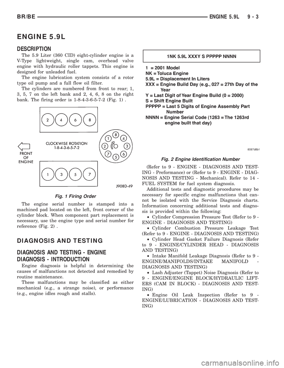
The cylinders are numbered from front to rear; 1,
3, 5, 7 on the left bank and 2, 4, 6, 8 on the right
bank. The firing order is 1-8-4-3-6-5-7-2 (Fig. 1) .
The engine serial number is stamped into a
machined pad located on the left, front corner of the
cylinder block. When component part replacement is
necessary, use the engine type and serial number for
reference (Fig. 2) .
DIAGNOSIS AND TESTING
DIAGNOSIS AND TESTING - ENGINE
DIAGNOSIS - INTRODUCTION
Engine diagnosis is helpful in determining the
causes of malfunctions not detected and remedied by
routine maintenance.
These malfunctions may be classified as either
mechanical (e.g., a strange noise), or performance
(e.g., engine idles rough and stalls).(Refer to 9 - ENGINE - DIAGNOSIS AND TEST-
ING - Preformance) or (Refer to 9 - ENGINE - DIAG-
NOSIS AND TESTING - Mechanical). Refer to 14 -
FUEL SYSTEM for fuel system diagnosis.
Additional tests and diagnostic procedures may be
necessary for specific engine malfunctions that can-
not be isolated with the Service Diagnosis charts.
Information concerning additional tests and diagno-
sis is provided within the following:
²Cylinder Compression Pressure Test (Refer to 9 -
ENGINE - DIAGNOSIS AND TESTING)
²Cylinder Combustion Pressure Leakage Test
(Refer to 9 - ENGINE - DIAGNOSIS AND TESTING)
²Cylinder Head Gasket Failure Diagnosis (Refer
to 9 - ENGINE/CYLINDER HEAD - DIAGNOSIS
AND TESTING)
²Intake Manifold Leakage Diagnosis (Refer to 9 -
ENGINE/MANIFOLDS/INTAKE MANIFOLD -
DIAGNOSIS AND TESTING)
²Lash Adjuster (Tappet) Noise Diagnosis (Refer to
9 - ENGINE/ENGINE BLOCK/HYDRAULIC LIFT-
ERS (CAM IN BLOCK) - DIAGNOSIS AND TEST-
ING)
²Engine Oil Leak Inspection (Refer to 9 -
ENGINE/LUBRICATION - DIAGNOSIS AND TEST-
ING)
Fig. 1 Firing Order
Fig. 2 Engine Identification Number
BR/BEENGINE 5.9L 9 - 3