2002 DODGE RAM lubrication
[x] Cancel search: lubricationPage 1142 of 2255
(1) Perform the Fuel Pressure Release Procedure
(Refer to 14 - FUEL SYSTEM/FUEL DELIVERY -
STANDARD PROCEDURE).
(2) Disconnect the negative cable(s) from the bat-
tery.
(3) Inspect air cleaner, induction system, and
intake manifold to ensure system is dry and clear of
foreign material.
(4) Place a shop towel around the spark plugs to
catch any fluid that may possibly be under pressure
in the cylinder head. Remove the spark plugs.
(5) With all spark plugs removed, rotate the crank-
shaft using a breaker bar and socket.
(6) Identify the fluid in the cylinders (coolant, fuel,
oil, etc.).
(7) Be sure all fluid has been removed from the
cylinders.
(8) Repair engine or components as necessary to
prevent this problem from occurring again.
(9) Squirt a small amount of engine oil into the
cylinders to lubricate the walls. This will prevent
damage on restart.
(10) Install new spark plugs. Tighten the spark
plugs to 41 N´m (30 ft. lbs.) torque.
(11) Drain engine oil. Remove and discard the oil
filter.
(12) Install the drain plug. Tighten the plug to 34
N´m (25 ft. lbs.) torque.
(13) Install a new oil filter.
(14) Fill engine crankcase with the specified
amount and grade of oil. (Refer to LUBRICATION &
MAINTENANCE - SPECIFICATIONS).
(15) Connect the negative cable(s) to the battery.
(16) Start the engine and check for any leaks.
REMOVAL
(1) Remove the battery.
(2) Drain cooling system (Refer to 7 - COOLING -
STANDARD PROCEDURE).
(3) Discharge the air conditioning system, if
equipped (Refer to 24 - HEATING & AIR CONDI-
TIONING/PLUMBING - STANDARD PROCEDURE).
(4) Remove the upper crossmember.
(5) Remove the transmission oil cooler (Refer to 7 -
COOLING/TRANSMISSION/TRANS COOLER -
REMOVAL).
(6) Remove the serpentine belt (Refer to 7 - COOL-
ING/ACCESSORY DRIVE/DRIVE BELTS - REMOV-
AL).
(7) Remove the A/C compressor with the lines
attached (Refer to 24 - HEATING & AIR CONDI-
TIONING/PLUMBING/A/C COMPRESSOR -
REMOVAL). Set aside.
(8) If equipped, remove the condenser (Refer to 24
- HEATING & AIR CONDITIONING/PLUMBING/
A/C CONDENSER - REMOVAL).(9) Remove the washer fluid reservoir bottle (Refer
to 8 - ELECTRICAL/WIPERS/WASHERS -
REMOVAL AND INSTALLATION).
(10) Disconnect the top radiator hose.
(11) Remove the fan (Refer to 7 - COOLING/EN-
GINE/RADIATOR FAN - REMOVAL).
(12) Remove the fan shroud.
(13) Disconnect the lower radiator hose.
(14) Disconnect the transmission cooler lines.
(15) Remove radiator (Refer to 7 - COOLING/EN-
GINE/RADIATOR - REMOVAL).
(16) Remove the generator with the wire connec-
tions (Refer to 8 - ELECTRICAL/CHARGING/GEN-
ERATOR - REMOVAL).
(17) Remove the air cleaner.
(18) Disconnect the throttle linkage.
(19) Remove throttle body (Refer to 14 - FUEL
SYSTEM/FUEL INJECTION/THROTTLE BODY -
REMOVAL).
(20) Remove the upper intake manifold (Refer to 9
- ENGINE/MANIFOLDS/INTAKE MANIFOLD -
REMOVAL).
(21) Remove the coil assemblies with the ignition
cables.
(22) Disconnect the heater hoses.
(23) Disconnect the power steering hoses, if
equipped.
(24) Perform the Fuel System Pressure release
procedure (Refer to 14 - FUEL SYSTEM/FUEL
DELIVERY - STANDARD PROCEDURE). Disconnect
the fuel line (Refer to 14 - FUEL SYSTEM/FUEL
DELIVERY/QUICK CONNECT FITTING - STAN-
DARD PROCEDURE).
(25) On Manual Transmission vehicles, remove the
shift lever.
(26) Raise and support the vehicle on a hoist.
(27) Remove the drain plug and drain the engine
oil.
(28) Loosen front engine mount thru-bolt nuts.
(29) Remove the transmission cooler line brackets
from oil pan.
(30) Disconnect exhaust pipe at manifold.
(31) Disconnect the starter wires. Remove starter
motor (Refer to 8 - ELECTRICAL/STARTING/
STARTER MOTOR - REMOVAL).
(32) Remove transmission.
(33) Lower vehicle.
CAUTION: DO NOT lift the engine by the intake
manifold.
(34) Install an engine lifting fixture.
(35) Remove engine from vehicle and install
engine assembly on a repair stand.
BR/BEENGINE 8.0L 9 - 67
ENGINE 8.0L (Continued)
Page 1150 of 2255
AIR CLEANER ELEMENT
REMOVAL - 8.0L
For air cleaner element required maintenance
schedules (listed in time or mileage intervals), refer
to 0, Lubrication and Maintenance.
A small amount of engine oil wetting the inside of
the air cleaner housing is normal. When servicing,
wipe out oil from air cleaner housing.
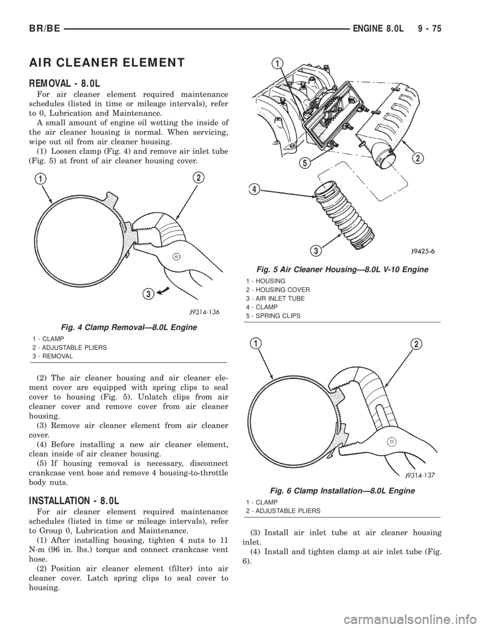
(1) Loosen clamp (Fig. 4) and remove air inlet tube
(Fig. 5) at front of air cleaner housing cover.
(2) The air cleaner housing and air cleaner ele-
ment cover are equipped with spring clips to seal
cover to housing (Fig. 5). Unlatch clips from air
cleaner cover and remove cover from air cleaner
housing.
(3) Remove air cleaner element from air cleaner
cover.
(4) Before installing a new air cleaner element,
clean inside of air cleaner housing.
(5) If housing removal is necessary, disconnect
crankcase vent hose and remove 4 housing-to-throttle
body nuts.
INSTALLATION - 8.0L
For air cleaner element required maintenance
schedules (listed in time or mileage intervals), refer
to Group 0, Lubrication and Maintenance.
(1) After installing housing, tighten 4 nuts to 11
N´m (96 in. lbs.) torque and connect crankcase vent
hose.
(2) Position air cleaner element (filter) into air
cleaner cover. Latch spring clips to seal cover to
housing.(3) Install air inlet tube at air cleaner housing
inlet.
(4) Install and tighten clamp at air inlet tube (Fig.
6).
Fig. 4 Clamp RemovalÐ8.0L Engine
1 - CLAMP
2 - ADJUSTABLE PLIERS
3 - REMOVAL
Fig. 5 Air Cleaner HousingÐ8.0L V-10 Engine
1 - HOUSING
2 - HOUSING COVER
3 - AIR INLET TUBE
4 - CLAMP
5 - SPRING CLIPS
Fig. 6 Clamp InstallationÐ8.0L Engine
1 - CLAMP
2 - ADJUSTABLE PLIERS
BR/BEENGINE 8.0L 9 - 75
Page 1159 of 2255
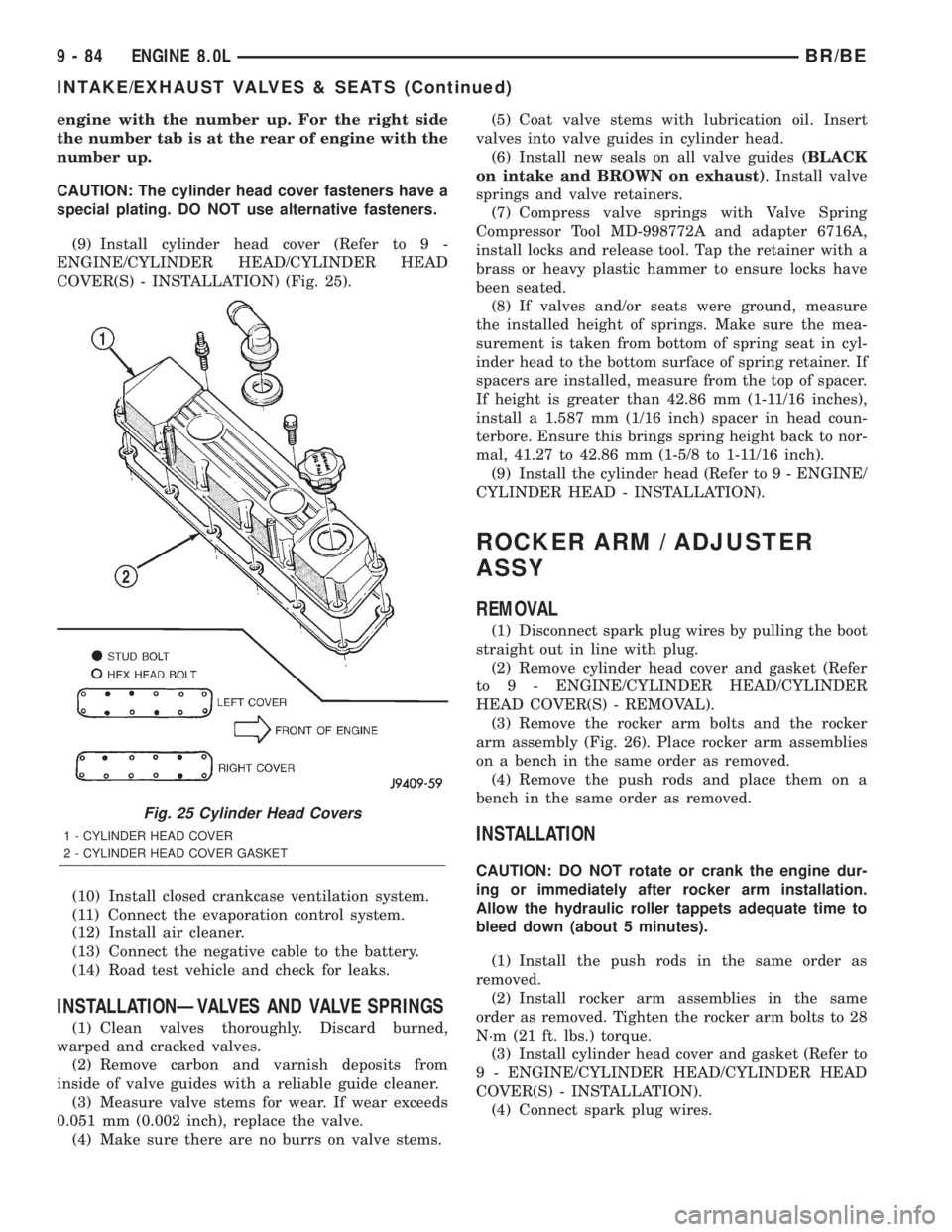
engine with the number up. For the right side
the number tab is at the rear of engine with the
number up.
CAUTION: The cylinder head cover fasteners have a
special plating. DO NOT use alternative fasteners.
(9) Install cylinder head cover (Refer to 9 -
ENGINE/CYLINDER HEAD/CYLINDER HEAD
COVER(S) - INSTALLATION) (Fig. 25).
(10) Install closed crankcase ventilation system.
(11) Connect the evaporation control system.
(12) Install air cleaner.
(13) Connect the negative cable to the battery.
(14) Road test vehicle and check for leaks.
INSTALLATIONÐVALVES AND VALVE SPRINGS
(1) Clean valves thoroughly. Discard burned,
warped and cracked valves.
(2) Remove carbon and varnish deposits from
inside of valve guides with a reliable guide cleaner.
(3) Measure valve stems for wear. If wear exceeds
0.051 mm (0.002 inch), replace the valve.
(4) Make sure there are no burrs on valve stems.(5) Coat valve stems with lubrication oil. Insert
valves into valve guides in cylinder head.
(6) Install new seals on all valve guides(BLACK
on intake and BROWN on exhaust). Install valve
springs and valve retainers.
(7) Compress valve springs with Valve Spring
Compressor Tool MD-998772A and adapter 6716A,
install locks and release tool. Tap the retainer with a
brass or heavy plastic hammer to ensure locks have
been seated.
(8) If valves and/or seats were ground, measure
the installed height of springs. Make sure the mea-
surement is taken from bottom of spring seat in cyl-
inder head to the bottom surface of spring retainer. If
spacers are installed, measure from the top of spacer.
If height is greater than 42.86 mm (1-11/16 inches),
install a 1.587 mm (1/16 inch) spacer in head coun-
terbore. Ensure this brings spring height back to nor-
mal, 41.27 to 42.86 mm (1-5/8 to 1-11/16 inch).
(9) Install the cylinder head (Refer to 9 - ENGINE/
CYLINDER HEAD - INSTALLATION).
ROCKER ARM / ADJUSTER
ASSY
REMOVAL
(1) Disconnect spark plug wires by pulling the boot
straight out in line with plug.
(2) Remove cylinder head cover and gasket (Refer
to 9 - ENGINE/CYLINDER HEAD/CYLINDER
HEAD COVER(S) - REMOVAL).
(3) Remove the rocker arm bolts and the rocker
arm assembly (Fig. 26). Place rocker arm assemblies
on a bench in the same order as removed.
(4) Remove the push rods and place them on a
bench in the same order as removed.
INSTALLATION
CAUTION: DO NOT rotate or crank the engine dur-
ing or immediately after rocker arm installation.
Allow the hydraulic roller tappets adequate time to
bleed down (about 5 minutes).
(1) Install the push rods in the same order as
removed.
(2) Install rocker arm assemblies in the same
order as removed. Tighten the rocker arm bolts to 28
N´m (21 ft. lbs.) torque.
(3) Install cylinder head cover and gasket (Refer to
9 - ENGINE/CYLINDER HEAD/CYLINDER HEAD
COVER(S) - INSTALLATION).
(4) Connect spark plug wires.
Fig. 25 Cylinder Head Covers
1 - CYLINDER HEAD COVER
2 - CYLINDER HEAD COVER GASKET
9 - 84 ENGINE 8.0LBR/BE
INTAKE/EXHAUST VALVES & SEATS (Continued)
Page 1163 of 2255
(8) Remove the upper main bearings from the
block.
INSTALLATION
When a crankshaft is replaced, all main and con-
necting rod bearings should be replaced with new
bearings. Therefore, selective fitting of the bearings
is not required when a crankshaft and bearings are
replaced.
NOTE: Lubricate crankshaft main bearings with
clean engine oil.
(1) Position upper main bearings into block.
(2) Position the crankshaft into the cylinder block.
(3) Lubricate the main journals with clean engine
oil. Install upper main bearings, caps and bolts. Fol-
low the 2 step tightening sequence, starting with
main bearing cap 1.
(4) Lubricate the connecting rod bearings and jour-
nals with clean engine oil. Carefully install connect-
ing rods to the crankshaft.
(5) Using Special Tool 8359 Seal Installer install
new oil into oil seal retainer.
(6) Using Special Tool 6687 Guide, install the rear
seal retainer with a new gasket.
(7) Install the timing chain cover with a new gas-
ket and oil seal.
(8) Prime oil pump by squirt oil in the oil filter
mounting hole and filling the J-trap of the front tim-
ing cover. When oil is running out, install oil filter
that has been filled with oil.
(9) Apply a rearward axial load of 667 N (150
lbs-f) on crankshaft centerline, driving No.3 main cap
and thrust bearing against No.3 bulkhead. Repeat
procedure, driving crankshaft forward to align rear
flange of thrust bearings in a common plane. Front
face of No.1 main cap must not extend forward in
front of face of No.1 bulkhead.
(10) Install the oil pickup tube. Tighten the bolts
to 16 N´m (144 in. lbs.) torque.
(11) Install the oil pan.
CRANKSHAFT MAIN
BEARINGS
STANDARD PROCEDUREÐFITTING
CRANKSHAFT MAIN BEARINGS
Bearing caps are not interchangeable and should
be marked at removal to ensure correct assembly.
Upper and lower bearing halves are NOT inter-
changeable. All lower main bearing halves are inter-
changeable. Upper main bearing halves of No. 2, 4,
and 5 are interchangeable. Upper main bearinghalves of No. 1 and 6 are interchangeable, this also
applies to the lower bearing halves.
The No.3 main bearing is flanged to carry the
crankshaft thrust loads. This bearing is NOT inter-
changeable with any other bearing halves in the
engine. Bearing shells are available in standard and
the following undersizes: 0.25 mm (0.001 inch), 0.051
mm (0.002 inch), 0.076 mm (0.003 inch), 0.254 mm
(0.010 inch) and 0.305 mm (0.012 inch). Never install
an undersize bearing that will reduce clearance
below specifications.
REMOVAL
(1) Remove the oil pan and oil pump pick-up tube
(Refer to 9 - ENGINE/LUBRICATION/OIL PAN -
REMOVAL).
(2) Identify bearing caps before removal. Remove
bearing caps one at a time.
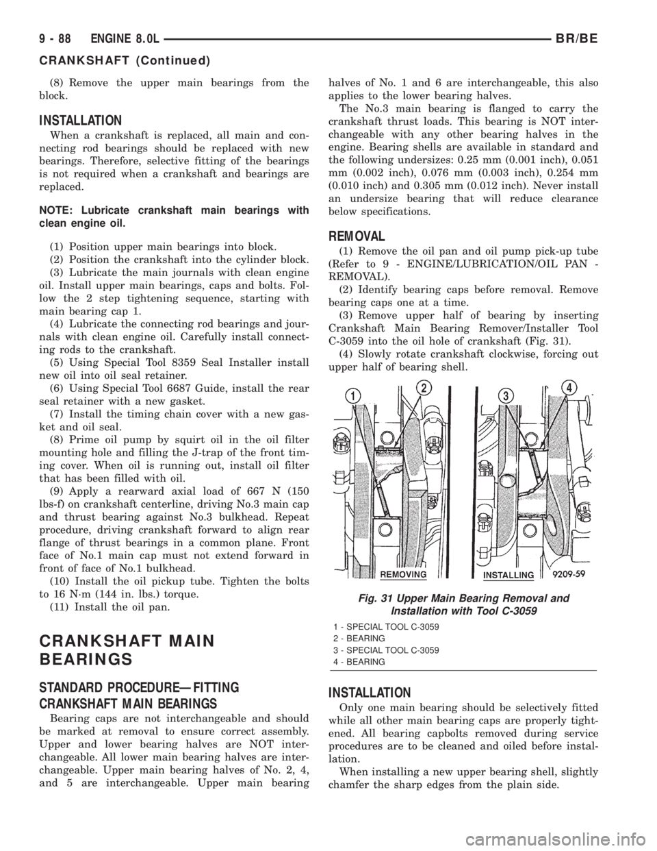
(3) Remove upper half of bearing by inserting
Crankshaft Main Bearing Remover/Installer Tool
C-3059 into the oil hole of crankshaft (Fig. 31).
(4) Slowly rotate crankshaft clockwise, forcing out
upper half of bearing shell.
INSTALLATION
Only one main bearing should be selectively fitted
while all other main bearing caps are properly tight-
ened. All bearing capbolts removed during service
procedures are to be cleaned and oiled before instal-
lation.
When installing a new upper bearing shell, slightly
chamfer the sharp edges from the plain side.
Fig. 31 Upper Main Bearing Removal and
Installation with Tool C-3059
1 - SPECIAL TOOL C-3059
2 - BEARING
3 - SPECIAL TOOL C-3059
4 - BEARING
9 - 88 ENGINE 8.0LBR/BE
CRANKSHAFT (Continued)
Page 1164 of 2255
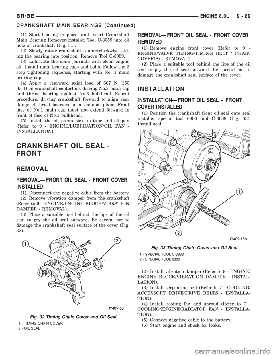
(1) Start bearing in place, and insert Crankshaft
Main Bearing Remover/Installer Tool C-3059 into oil
hole of crankshaft (Fig. 31).
(2) Slowly rotate crankshaft counterclockwise slid-
ing the bearing into position. Remove Tool C-3059.
(3) Lubricate the main journals with clean engine
oil. Install main bearing caps and bolts. Follow the 2
step tightening sequence, starting with No. 1 main
bearing cap.
(4) Apply a rearward axial load of 667 N (150
lbs-f) on crankshaft centerline, driving No.3 main cap
and thrust bearing against No.3 bulkhead. Repeat
procedure, driving crankshaft forward to align rear
flange of thrust bearings in a common plane. Front
face of No.1 main cap must not extend forward in
front of face of No.1 bulkhead.
(5) Install the oil pump pick-up tube and oil pan
(Refer to 9 - ENGINE/LUBRICATION/OIL PAN -
INSTALLATION).
CRANKSHAFT OIL SEAL -
FRONT
REMOVAL
REMOVALÐFRONT OIL SEAL - FRONT COVER
INSTALLED
(1) Disconnect the negative cable from the battery.
(2) Remove vibration damper from the crankshaft
(Refer to 9 - ENGINE/ENGINE BLOCK/VIBRATION
DAMPER - REMOVAL).
(3) Place a suitable tool behind the lips of the oil
seal to pry the oil seal outward. Be careful not to
damage the crankshaft seal surface of the cover (Fig.
32).
REMOVALÐFRONT OIL SEAL - FRONT COVER
REMOVED
(1) Remove engine front cover (Refer to 9 -
ENGINE/VALVE TIMING/TIMING BELT / CHAIN
COVER(S) - REMOVAL).
(2) Place a suitable tool behind the lips of the oil
seal to pry the oil seal outward. Be careful not to
damage the crankshaft seal surface of the cover.
INSTALLATION
INSTALLATIONÐFRONT OIL SEAL ± FRONT
COVER INSTALLED
(1) Position the crankshaft front oil seal onto seal
installer special tool 6806 and C-3688 (Fig. 33).
Install seal.
(2) Install vibration damper (Refer to 9 - ENGINE/
ENGINE BLOCK/VIBRATION DAMPER - INSTAL-
LATION).
(3) Install serpentine belt (Refer to 7 - COOLING/
ACCESSORY DRIVE/DRIVE BELTS - INSTALLA-
TION).
(4) Install cooling fan and shroud (Refer to 7 -
COOLING/ENGINE/RADIATOR FAN - INSTALLA-
TION).
(5) Connect negative cable to the battery.
(6) Start engine and check for leaks.
Fig. 32 Timing Chain Cover and Oil Seal
1 - TIMING CHAIN COVER
2 - OIL SEAL
Fig. 33 Timing Chain Cover and Oil Seal
1 - SPECIAL TOOL C-3688
2 - SPECIAL TOOL 6806
BR/BEENGINE 8.0L 9 - 89
CRANKSHAFT MAIN BEARINGS (Continued)
Page 1166 of 2255
(2) Use extream care and clean all gasket resdue
from the retainer.
(3) Apply a small amount of MopartSilicone Rub-
ber Adhesive Sealant to the retainer gasket. Position
the gasket onto the retainer.
(4) Position Special Tool 6687 Seal Guide onto the
crankshaft.
(5) Position the retainer and seal over the guide
and onto the engine block.
(6) Install the retainer mounting bolts. Tighten the
bolts to 22 N´m (16 ft. lbs.).
(7) Install the oil pan (Refer to 9 - ENGINE/LU-
BRICATION/OIL PAN - INSTALLATION).
(8) Install the drive plate / flywheel.
(9) Install the transmission.
(10) Check and verify engine oil level.
(11) Start engine and check for leaks.
HYDRAULIC LIFTERS
DIAGNOSIS AND TESTINGÐHYDRAULIC
TAPPETS
Before disassembling any part of the engine to cor-
rect tappet noise, check the oil pressure. If vehicle
has no oil pressure gauge, install a reliable gauge at
the pressure sending-unit. The pressure should be
between 207-552 kPa (30-80 psi) at 3,000 RPM.
Check the oil level after the engine reaches normal
operating temperature. Allow 5 minutes to stabilize
oil level, check dipstick. The oil level in the pan
should never be above the FULL mark or below the
ADD OIL mark on dipstick. Either of these two con-
ditions could be responsible for noisy tappets.
OIL LEVEL
HIGH
If oil level is above the FULL mark, it is possible
for the connecting rods to dip into the oil. With the
engine running, this condition could create foam in
the oil pan. Foam in oil pan would be fed to the
hydraulic tappets by the oil pump causing them to
lose length and allow valves to seat noisily.
LOW
Low oil level may allow oil pump to take in air.
When air is fed to the tappets, they lose length,
which allows valves to seat noisily. Any leaks on
intake side of oil pump through which air can be
drawn will create the same tappet action. Check the
lubrication system from the intake strainer to the
pump cover, including the relief valve retainer cap.
When tappet noise is due to aeration, it may be
intermittent or constant, and usually more than one
tappet will be noisy. When oil level and leaks havebeen corrected, operate the engine at fast idle. Run
engine for a sufficient time to allow all of the air
inside the tappets to be bled out.
TAPPET NOISE DIAGNOSIS
(1) To determine source of tappet noise, operate
engine at idle with cylinder head covers removed.
(2) Feel each valve spring or rocker arm to detect
noisy tappet. The noisy tappet will cause the affected
spring and/or rocker arm to vibrate or feel rough in
operation.
NOTE: Worn valve guides or cocked springs are
sometimes mistaken for noisy tappets. If such is
the case, noise may be dampened by applying side
thrust on the valve spring. If noise is not apprecia-
bly reduced, it can be assumed the noise is in the
tappet. Inspect the rocker arm push rod sockets
and push rod ends for wear.
(3) Valve tappet noise ranges from light noise to a
heavy click. A light noise is usually caused by exces-
sive leak-down around the unit plunger, or by the
plunger partially sticking in the tappet body cylinder.
The tappet should be replaced. A heavy click is
caused by a tappet check valve not seating, or by for-
eign particles wedged between the plunger and the
tappet body. This will cause the plunger to stick in
the down position. This heavy click will be accompa-
nied by excessive clearance between the valve stem
and rocker arm as valve closes. In either case, tappet
assembly should be removed for inspection and clean-
ing.
(4) The valve train generates a noise very much
like a light tappet noise during normal operation.
Care must be taken to ensure that tappets are mak-
ing the noise. If more than one tappet seems to be
noisy, it's probably not the tappets.
LEAK-DOWN TEST
After cleaning and inspection, test each tappet for
specified leak-down rate tolerance to ensure zero-lash
operation (Fig. 36).
Swing the weighted arm of the hydraulic valve tap-
pet tester away from the ram of the Universal Leak-
Down Tester.
(1) Place a 7.925-7.950 mm (0.312-0.313 inch)
diameter ball bearing on the plunger cap of the tap-
pet.
(2) Lift the ram and position the tappet (with the
ball bearing) inside the tester cup.
(3) Lower the ram, then adjust the nose of the ram
until it contacts the ball bearing. DO NOT tighten
the hex nut on the ram.
(4) Fill the tester cup with hydraulic valve tappet
test oil until the tappet is completely submerged.
BR/BEENGINE 8.0L 9 - 91
CRANKSHAFT REAR OIL SEAL RETAINER (Continued)
Page 1169 of 2255
coating on the piston will give the appearance of a
line-to-line fit with the cylinder bore.
REMOVAL
(1) Remove the engine from the vehicle (Refer to 9
- ENGINE - REMOVAL).
(2) Remove cylinder head (Refer to 9 - ENGINE/
CYLINDER HEAD - REMOVAL).
(3) Remove the oil pan and oil pump pick-up tube
(Refer to 9 - ENGINE/LUBRICATION/OIL PAN -
REMOVAL).
(4) Remove top ridge of cylinder bores with a reli-
able ridge reamer before removing pistons from cyl-
inder block. Be sure to keep tops of pistons covered
during this operation.
(5) Be sure the connecting rod and connecting rod
cap are identified with the cylinder number. Remove
connecting rod cap. Install connecting rod bolt guide
set on connecting rod bolts.
(6) Pistons and connecting rods must be removed
from top of cylinder block. When removing piston and
connecting rod assemblies, rotate crankshaft center
the connecting rod in the cylinder bore and at BDC.
Be careful not to nick crankshaft journals. DO
NOT try to remove black coating on skirt. This
is the dry film lubricant.
(7) After removal, install bearing cap on the mat-
ing rod.
CLEANING
Clean the piston and connecting rod assembly
using a suitable solvent.
INSPECTION
Check the connecting rod journal for excessive
wear, taper and scoring (Refer to 9 - ENGINE/EN-
GINE BLOCK/CONNECTING ROD BEARINGS -
STANDARD PROCEDURE).
Check the connecting rod for signs of twist or bend-
ing.
Check the piston for taper and elliptical shape
before it is fitted into the cylinder bore (Refer to 9 -
ENGINE/ENGINE BLOCK/PISTON & CONNECT-
ING ROD - STANDARD PROCEDURE).
Check the piston for scoring, or scraping marks in
the piston skirts. Check the ring lands for cracks
and/or deterioration.
INSTALLATION
(1) Check the crankshaft connecting rod journal
for excessive wear, taper and scoring.
(2) Check the cylinder block bore for out-of-round,
taper, scoring and scuffing.
(3) Be sure that compression ring gaps are stag-
gered so that neither is in line with oil ring rail gap.
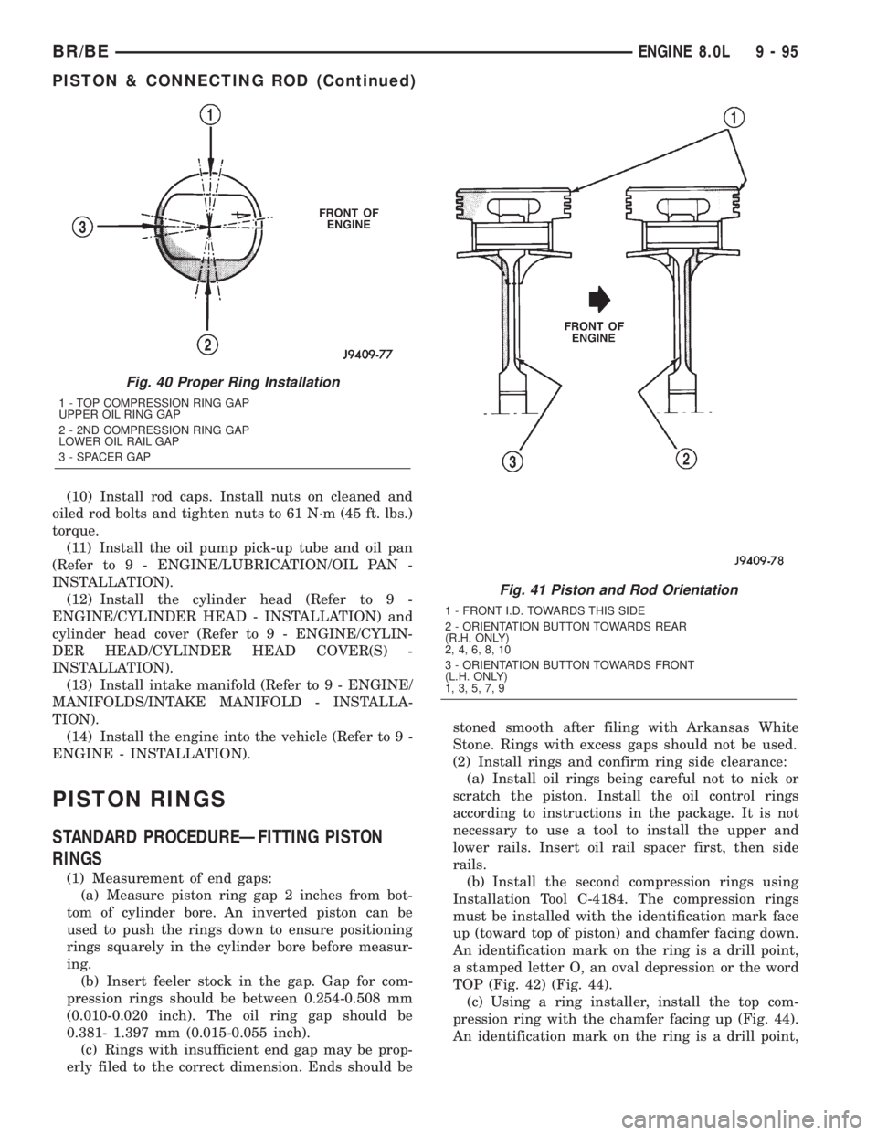
(4) Before installing the ring compressor, make
sure the oil ring expander ends are butted and the
rail gaps located properly (Fig. 40).
NOTE: Be sure position of rings does not change
during the following step.
(5) Immerse the piston head and rings in clean
engine oil. Slide Piston Ring Compressor Tool C-385
over the piston and tighten with the special wrench
(part of Tool C-385).
(6) Install connecting rod bolt protectors on rod
bolts, a long protector should be installed on the
numbered side of the connecting rod.
(7) Rotate crankshaft so that the connecting rod
journal is on the center of the cylinder bore in the
bottom dead center (BDC) position. Be sure connect-
ing rod and cylinder bore number are the same.
Insert rod and piston into cylinder bore. Be sure the
piston and rod assemblies are installed in the proper
orientation (Fig. 41).
(8) The notch, groove or arrow on top of piston
must be pointing toward front of engine. The larger
chamfer of the connecting rod bore must be installed
toward crankshaft journal fillet.
(9) While tapping the piston down in cylinder bore
with the handle of a hammer, guide the connecting
rod over the crankshaft journal.
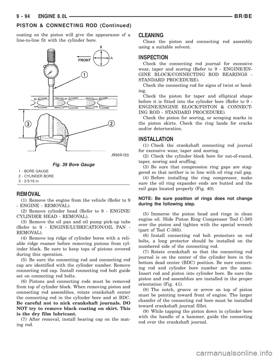
Fig. 39 Bore Gauge
1 - BORE GAUGE
2 - CYLINDER BORE
3 - 2-5/16 in.
9 - 94 ENGINE 8.0LBR/BE
PISTON & CONNECTING ROD (Continued)
Page 1170 of 2255
(10) Install rod caps. Install nuts on cleaned and
oiled rod bolts and tighten nuts to 61 N´m (45 ft. lbs.)
torque.
(11) Install the oil pump pick-up tube and oil pan
(Refer to 9 - ENGINE/LUBRICATION/OIL PAN -
INSTALLATION).
(12) Install the cylinder head (Refer to 9 -
ENGINE/CYLINDER HEAD - INSTALLATION) and
cylinder head cover (Refer to 9 - ENGINE/CYLIN-
DER HEAD/CYLINDER HEAD COVER(S) -
INSTALLATION).
(13) Install intake manifold (Refer to 9 - ENGINE/
MANIFOLDS/INTAKE MANIFOLD - INSTALLA-
TION).
(14) Install the engine into the vehicle (Refer to 9 -
ENGINE - INSTALLATION).
PISTON RINGS
STANDARD PROCEDUREÐFITTING PISTON
RINGS
(1) Measurement of end gaps:
(a) Measure piston ring gap 2 inches from bot-
tom of cylinder bore. An inverted piston can be
used to push the rings down to ensure positioning
rings squarely in the cylinder bore before measur-
ing.
(b) Insert feeler stock in the gap. Gap for com-
pression rings should be between 0.254-0.508 mm
(0.010-0.020 inch). The oil ring gap should be
0.381- 1.397 mm (0.015-0.055 inch).
(c) Rings with insufficient end gap may be prop-
erly filed to the correct dimension. Ends should bestoned smooth after filing with Arkansas White
Stone. Rings with excess gaps should not be used.
(2) Install rings and confirm ring side clearance:
(a) Install oil rings being careful not to nick or
scratch the piston. Install the oil control rings
according to instructions in the package. It is not
necessary to use a tool to install the upper and
lower rails. Insert oil rail spacer first, then side
rails.
(b) Install the second compression rings using
Installation Tool C-4184. The compression rings
must be installed with the identification mark face
up (toward top of piston) and chamfer facing down.
An identification mark on the ring is a drill point,
a stamped letter O, an oval depression or the word
TOP (Fig. 42) (Fig. 44).
(c) Using a ring installer, install the top com-
pression ring with the chamfer facing up (Fig. 44).
An identification mark on the ring is a drill point,
Fig. 40 Proper Ring Installation
1 - TOP COMPRESSION RING GAP
UPPER OIL RING GAP
2 - 2ND COMPRESSION RING GAP
LOWER OIL RAIL GAP
3 - SPACER GAP
Fig. 41 Piston and Rod Orientation
1 - FRONT I.D. TOWARDS THIS SIDE
2 - ORIENTATION BUTTON TOWARDS REAR
(R.H. ONLY)
2, 4, 6, 8, 10
3 - ORIENTATION BUTTON TOWARDS FRONT
(L.H. ONLY)
1, 3, 5, 7, 9
BR/BEENGINE 8.0L 9 - 95
PISTON & CONNECTING ROD (Continued)