2002 DODGE RAM engine oil
[x] Cancel search: engine oilPage 1286 of 2255
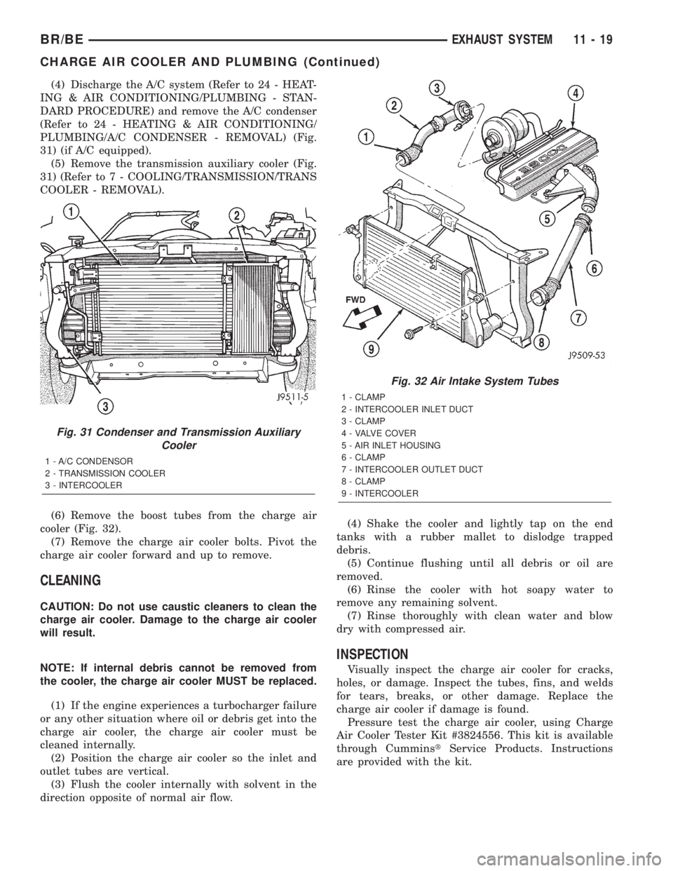
(4) Discharge the A/C system (Refer to 24 - HEAT-
ING & AIR CONDITIONING/PLUMBING - STAN-
DARD PROCEDURE) and remove the A/C condenser
(Refer to 24 - HEATING & AIR CONDITIONING/
PLUMBING/A/C CONDENSER - REMOVAL) (Fig.
31) (if A/C equipped).
(5) Remove the transmission auxiliary cooler (Fig.
31) (Refer to 7 - COOLING/TRANSMISSION/TRANS
COOLER - REMOVAL).
(6) Remove the boost tubes from the charge air
cooler (Fig. 32).
(7) Remove the charge air cooler bolts. Pivot the
charge air cooler forward and up to remove.
CLEANING
CAUTION: Do not use caustic cleaners to clean the
charge air cooler. Damage to the charge air cooler
will result.
NOTE: If internal debris cannot be removed from
the cooler, the charge air cooler MUST be replaced.
(1) If the engine experiences a turbocharger failure
or any other situation where oil or debris get into the
charge air cooler, the charge air cooler must be
cleaned internally.
(2) Position the charge air cooler so the inlet and
outlet tubes are vertical.
(3) Flush the cooler internally with solvent in the
direction opposite of normal air flow.(4) Shake the cooler and lightly tap on the end
tanks with a rubber mallet to dislodge trapped
debris.
(5) Continue flushing until all debris or oil are
removed.
(6) Rinse the cooler with hot soapy water to
remove any remaining solvent.
(7) Rinse thoroughly with clean water and blow
dry with compressed air.
INSPECTION
Visually inspect the charge air cooler for cracks,
holes, or damage. Inspect the tubes, fins, and welds
for tears, breaks, or other damage. Replace the
charge air cooler if damage is found.
Pressure test the charge air cooler, using Charge
Air Cooler Tester Kit #3824556. This kit is available
through CumminstService Products. Instructions
are provided with the kit.
Fig. 31 Condenser and Transmission Auxiliary
Cooler
1 - A/C CONDENSOR
2 - TRANSMISSION COOLER
3 - INTERCOOLER
Fig. 32 Air Intake System Tubes
1 - CLAMP
2 - INTERCOOLER INLET DUCT
3 - CLAMP
4 - VALVE COVER
5 - AIR INLET HOUSING
6 - CLAMP
7 - INTERCOOLER OUTLET DUCT
8 - CLAMP
9 - INTERCOOLER
BR/BEEXHAUST SYSTEM 11 - 19
CHARGE AIR COOLER AND PLUMBING (Continued)
Page 1310 of 2255
WARNING: BEFORE PROCEEDING TO NEXT STEP,
NOTE THE FUEL PUMP WILL BE ACTIVATED AND
SYSTEM PRESSURE WILL BE PRESENT. THIS WILL
OCCUR AFTER CONNECTING TEST LEADS FROM
LCS ADAPTER INTO FUEL PUMP RELAY CAVITIES.
THE FUEL PUMP WILL OPERATE EVEN WITH IGNI-
TION KEY IN OFF POSITION. BEFORE ATTACHING
TEST LEADS, BE SURE ALL FUEL LINES AND
FUEL SYSTEM COMPONENTS ARE CONNECTED.
CAUTION: To prevent possible damage to the vehi-
cle electrical system and LCS adapter, the test
leads must be connected into relay cavities exactly
as shown in following steps.
Depending upon vehicle model, year or engine con-
figuration, three different types of relays may be
used: Type-1, type-2 and type±3.
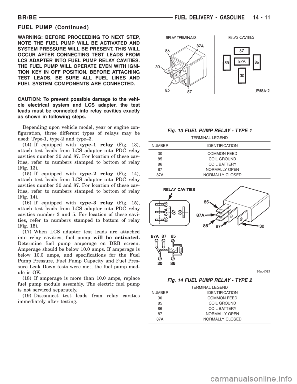
(14) If equipped withtype±1 relay(Fig. 13),
attach test leads from LCS adapter into PDC relay
cavities number 30 and 87. For location of these cav-
ities, refer to numbers stamped to bottom of relay
(Fig. 13).
(15) If equipped withtype±2 relay(Fig. 14),
attach test leads from LCS adapter into PDC relay
cavities number 30 and 87. For location of these cav-
ities, refer to numbers stamped to bottom of relay
(Fig. 14).
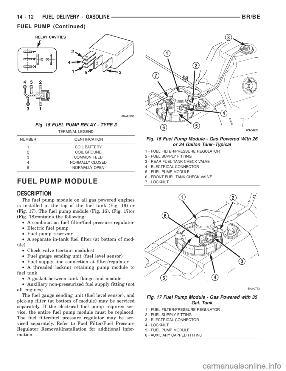
(16) If equipped withtype±3 relay(Fig. 15),
attach test leads from LCS adapter into PDC relay
cavities number 3 and 5. For location of these cavi-
ties, refer to numbers stamped to bottom of relay
(Fig. 15).
(17) When LCS adapter test leads are attached
into relay cavities, fuel pumpwill be activated.
Determine fuel pump amperage on DRB screen.
Amperage should be below 10.0 amps. If amperage is
below 10.0 amps, and specifications for the Fuel
Pump Pressure, Fuel Pump Capacity and Fuel Pres-
sure Leak Down tests were met, the fuel pump mod-
ule is OK.
(18) If amperage is more than 10.0 amps, replace
fuel pump module assembly. The electric fuel pump
is not serviced separately.
(19) Disconnect test leads from relay cavities
immediately after testing.
Fig. 13 FUEL PUMP RELAY - TYPE 1
TERMINAL LEGEND
NUMBER IDENTIFICATION
30 COMMON FEED
85 COIL GROUND
86 COIL BATTERY
87 NORMALLY OPEN
87A NORMALLY CLOSED
Fig. 14 FUEL PUMP RELAY - TYPE 2
TERMINAL LEGEND
NUMBER IDENTIFICATION
30 COMMON FEED
85 COIL GROUND
86 COIL BATTERY
87 NORMALLY OPEN
87A NORMALLY CLOSED
BR/BEFUEL DELIVERY - GASOLINE 14 - 11
FUEL PUMP (Continued)
Page 1311 of 2255
FUEL PUMP MODULE
DESCRIPTION
The fuel pump module on all gas powered engines
is installed in the top of the fuel tank (Fig. 16) or
(Fig. 17). The fuel pump module (Fig. 16), (Fig. 17)or
(Fig. 18)contains the following:
²A combination fuel filter/fuel pressure regulator
²Electric fuel pump
²Fuel pump reservoir
²A separate in-tank fuel filter (at bottom of mod-
ule)
²Check valve (certain modules)
²Fuel gauge sending unit (fuel level sensor)
²Fuel supply line connection at filter/regulator
²A threaded locknut retaining pump module to
fuel tank
²A gasket between tank flange and module
²Auxiliary non-pressurized fuel supply fitting (not
all engines)
The fuel gauge sending unit (fuel level sensor), and
pick-up filter (at bottom of module) may be serviced
separately. If the electrical fuel pump requires ser-
vice, the entire fuel pump module must be replaced.
The fuel filter/fuel pressure regulator may be ser-
viced separately. Refer to Fuel Filter/Fuel Pressure
Regulator Removal/Installation for additional infor-
mation.
Fig. 15 FUEL PUMP RELAY - TYPE 3
TERMINAL LEGEND
NUMBER IDENTIFICATION
1 COIL BATTERY
2 COIL GROUND
3 COMMON FEED
4 NORMALLY CLOSED
5 NORMALLY OPEN
Fig. 16 Fuel Pump Module - Gas Powered With 26
or 34 Gallon Tank±Typical
1 - FUEL FILTER/PRESSURE REGULATOR
2 - FUEL SUPPLY FITTING
3 - REAR FUEL TANK CHECK VALVE
4 - ELECTRICAL CONNECTOR
5 - FUEL PUMP MODULE
6 - FRONT FUEL TANK CHECK VALVE
7 - LOCKNUT
Fig. 17 Fuel Pump Module - Gas Powered with 35
Gal. Tank
1 - FUEL FILTER/PRESSURE REGULATOR
2 - FUEL SUPPLY FITTING
3 - ELECTRICAL CONNECTOR
4 - LOCKNUT
5 - FUEL PUMP MODULE
6 - AUXILIARY CAPPED FITTING
14 - 12 FUEL DELIVERY - GASOLINEBR/BE
FUEL PUMP (Continued)
Page 1315 of 2255
(10) Remove fuel rail (with injectors attached)
from engine.
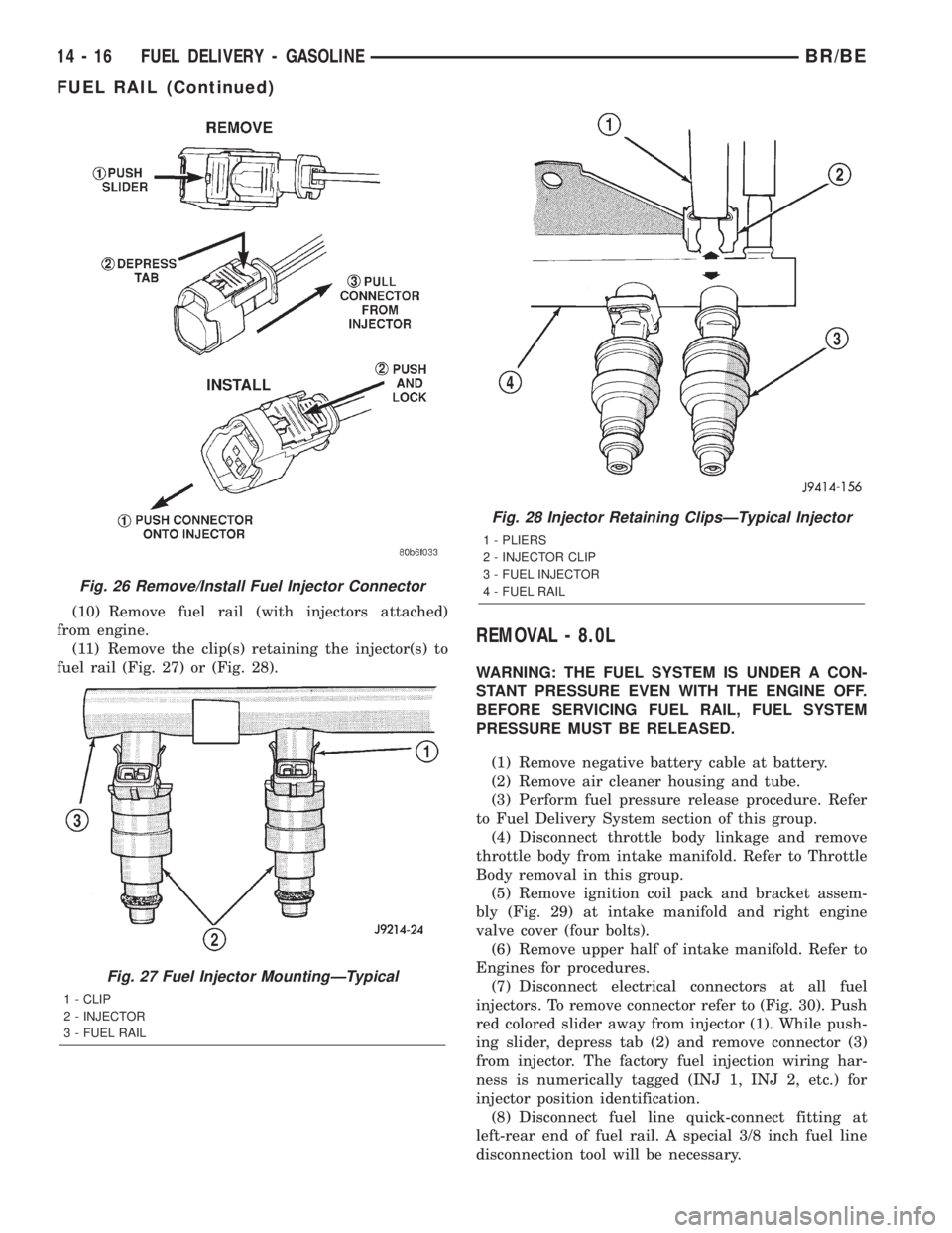
(11) Remove the clip(s) retaining the injector(s) to
fuel rail (Fig. 27) or (Fig. 28).
REMOVAL - 8.0L
WARNING: THE FUEL SYSTEM IS UNDER A CON-
STANT PRESSURE EVEN WITH THE ENGINE OFF.
BEFORE SERVICING FUEL RAIL, FUEL SYSTEM
PRESSURE MUST BE RELEASED.
(1) Remove negative battery cable at battery.
(2) Remove air cleaner housing and tube.
(3) Perform fuel pressure release procedure. Refer
to Fuel Delivery System section of this group.
(4) Disconnect throttle body linkage and remove
throttle body from intake manifold. Refer to Throttle
Body removal in this group.
(5) Remove ignition coil pack and bracket assem-
bly (Fig. 29) at intake manifold and right engine
valve cover (four bolts).
(6) Remove upper half of intake manifold. Refer to
Engines for procedures.
(7) Disconnect electrical connectors at all fuel
injectors. To remove connector refer to (Fig. 30). Push
red colored slider away from injector (1). While push-
ing slider, depress tab (2) and remove connector (3)
from injector. The factory fuel injection wiring har-
ness is numerically tagged (INJ 1, INJ 2, etc.) for
injector position identification.
(8) Disconnect fuel line quick-connect fitting at
left-rear end of fuel rail. A special 3/8 inch fuel line
disconnection tool will be necessary.
Fig. 26 Remove/Install Fuel Injector Connector
Fig. 27 Fuel Injector MountingÐTypical
1 - CLIP
2 - INJECTOR
3 - FUEL RAIL
Fig. 28 Injector Retaining ClipsÐTypical Injector
1 - PLIERS
2 - INJECTOR CLIP
3 - FUEL INJECTOR
4 - FUEL RAIL
14 - 16 FUEL DELIVERY - GASOLINEBR/BE
FUEL RAIL (Continued)
Page 1316 of 2255
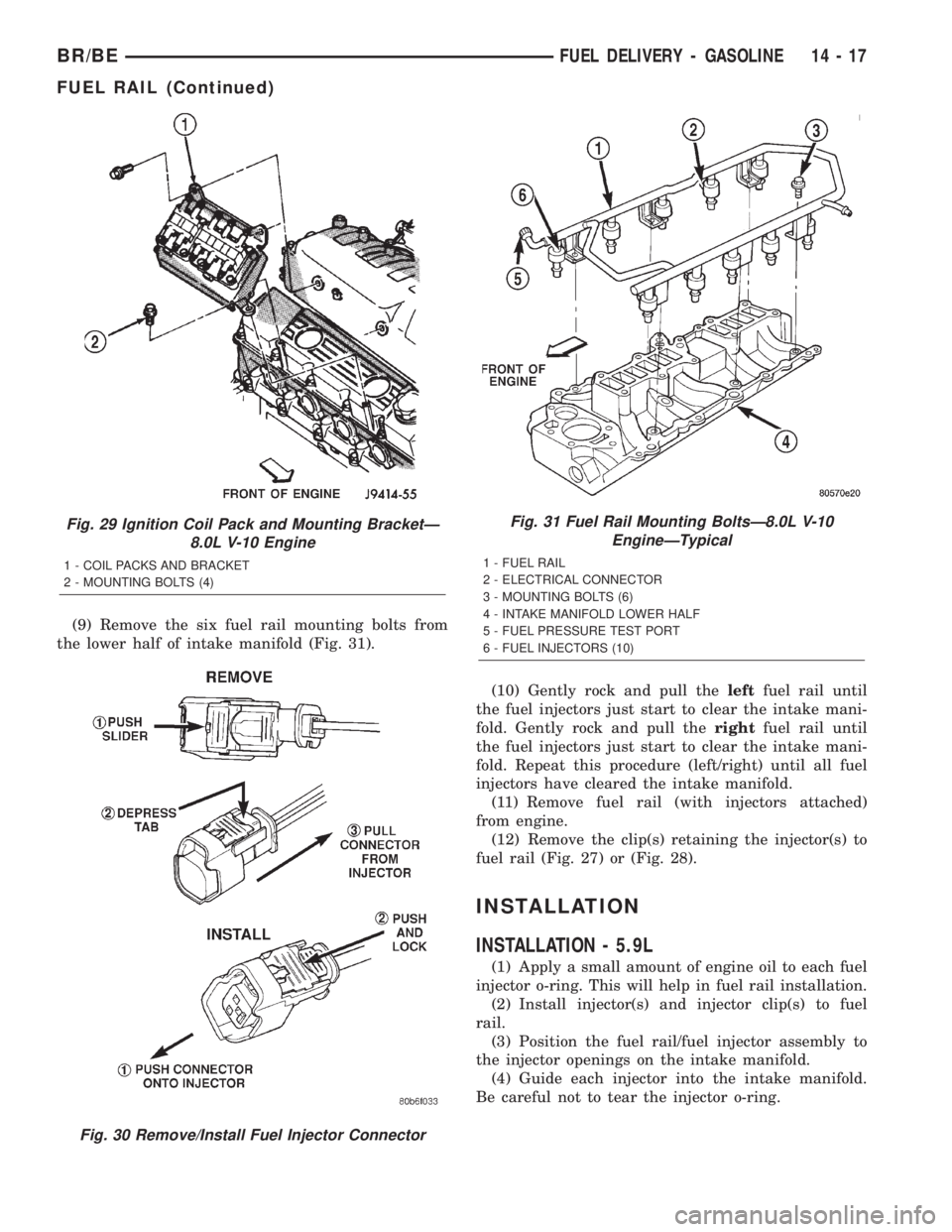
(9) Remove the six fuel rail mounting bolts from
the lower half of intake manifold (Fig. 31).
(10) Gently rock and pull theleftfuel rail until
the fuel injectors just start to clear the intake mani-
fold. Gently rock and pull therightfuel rail until
the fuel injectors just start to clear the intake mani-
fold. Repeat this procedure (left/right) until all fuel
injectors have cleared the intake manifold.
(11) Remove fuel rail (with injectors attached)
from engine.
(12) Remove the clip(s) retaining the injector(s) to
fuel rail (Fig. 27) or (Fig. 28).
INSTALLATION
INSTALLATION - 5.9L
(1) Apply a small amount of engine oil to each fuel
injector o-ring. This will help in fuel rail installation.
(2) Install injector(s) and injector clip(s) to fuel
rail.
(3) Position the fuel rail/fuel injector assembly to
the injector openings on the intake manifold.
(4) Guide each injector into the intake manifold.
Be careful not to tear the injector o-ring.
Fig. 29 Ignition Coil Pack and Mounting BracketÐ
8.0L V-10 Engine
1 - COIL PACKS AND BRACKET
2 - MOUNTING BOLTS (4)
Fig. 30 Remove/Install Fuel Injector Connector
Fig. 31 Fuel Rail Mounting BoltsÐ8.0L V-10
EngineÐTypical
1 - FUEL RAIL
2 - ELECTRICAL CONNECTOR
3 - MOUNTING BOLTS (6)
4 - INTAKE MANIFOLD LOWER HALF
5 - FUEL PRESSURE TEST PORT
6 - FUEL INJECTORS (10)
BR/BEFUEL DELIVERY - GASOLINE 14 - 17
FUEL RAIL (Continued)
Page 1317 of 2255
(5) Push therightfuel rail down until fuel injec-
tors have bottomed on injector shoulder. Push the
leftfuel rail down until fuel injectors have bottomed
on injector shoulder.
(6) Install fuel rail mounting bolts.
(7) Connect electrical connector to intake manifold
air temperature sensor.
(8) Connect electrical connectors at all fuel injec-
tors. To install connector, refer to (Fig. 26). Push con-
nector onto injector (1) and then push and lock red
colored slider (2). Verify connector is locked to injec-
tor by lightly tugging on connector.
(9) Install the A/C support bracket (if equipped).
(10) Install throttle body to intake manifold. Refer
to Throttle Body installation in this section of the
group.
(11) Install fuel tube (line) at side of fuel rail.
Refer to Quick-Connect Fittings for procedures.
(12) Install air cleaner.
(13) Connect battery cable to battery.
(14) Start engine and check for leaks.
INSTALLATION - 8.0L
(1) Apply a small amount of engine oil to each fuel
injector o-ring. This will help in fuel rail installation.
(2) Install injector(s) and injector clip(s) to fuel
rail.
NOTE: The fuel injector electrical connectors on all
10 injectors should be facing to the right (passen-
ger) side of the vehicle (Fig. 31).
(3) Position the fuel rail/fuel injector assembly to
the injector openings on the intake manifold.
(4) Guide each injector into the intake manifold.
Be careful not to tear the injector o-ring.
(5) Push therightfuel rail down until fuel injec-
tors have bottomed on injector shoulder. Push the
leftfuel rail down until fuel injectors have bottomed
on injector shoulder.
(6) Install the six fuel rail mounting bolts into the
lower half of intake manifold. Tighten bolts to 15
N´m (136 in. lbs.) torque.
(7) Connect electrical connectors at all fuel injec-
tors. To install connector, refer to (Fig. 30). Push con-
nector onto injector (1) and then push and lock red
colored slider (2). Verify connector is locked to injec-
tor by lightly tugging on connector. The injector wir-
ing harness is numerically tagged.
(8) Install upper half of intake manifold. Refer to
Engines for procedures.
(9) Connect main fuel line at fuel rail. Refer to
Quick-Connect Fittings for procedures.
(10) Install ignition coil pack and bracket assem-
bly at intake manifold and right engine valve cover
(four bolts).(11) Install throttle body to intake manifold. Refer
to Throttle Body removal in this group.
(12) Install throttle body linkage to throttle body.
(13) Install air cleaner tube and housing.
(14) Install negative battery cable at battery.
(15) Start engine and check for leaks.
FUEL TANK
DESCRIPTION
The fuel tank is constructed of a plastic material.
Its main functions are for fuel storage and for place-
ment of the fuel pump module.
OPERATION
All models pass a full 360 degree rollover test
without fuel leakage. To accomplish this, fuel and
vapor flow controls are required for all fuel tank con-
nections.
A fuel tank check valve(s) is mounted into the top
of the fuel tank (or pump module). Refer to Emission
Control System for fuel tank check valve information.
An evaporation control system is connected to the
rollover valve(s) to reduce emissions of fuel vapors
into the atmosphere. When fuel evaporates from the
fuel tank, vapors pass through vent hoses or tubes to
a charcoal canister where they are temporarily held.
When the engine is running, the vapors are drawn
into the intake manifold. Certain models are also
equipped with a self-diagnosing system using a Leak
Detection Pump (LDP). Refer to Emission Control
System for additional information.
REMOVAL
WARNING: GASOLINE POWERED ENGINES: THE
FUEL SYSTEM IS UNDER A CONSTANT PRESSURE
EVEN WITH THE ENGINE OFF. BEFORE SERVICING
THE FUEL TANK, FUEL SYSTEM PRESSURE MUST
BE RELEASED. REFER TO THE FUEL SYSTEM
PRESSURE RELEASE PROCEDURE BEFORE SER-
VICING THE FUEL TANK.
Two different procedures may be used to drain fuel
tank (lowering tank or using DRB scan tool). When
equipped with a diesel engine, the DRB scan tool
cannot be used (no electric fuel pump).
The quickest draining procedure involves lowering
the fuel tank.
Gasoline Powered Engines:As an alternative
procedure, the electric fuel pump may be activated
allowing tank to be drained at fuel rail connection.
Refer to DRB scan tool for fuel pump activation pro-
cedures. Before disconnecting fuel line at fuel rail,
release fuel pressure. Refer to the Fuel System Pres-
sure Release Procedure in this group for procedures.
14 - 18 FUEL DELIVERY - GASOLINEBR/BE
FUEL RAIL (Continued)
Page 1326 of 2255
(8)Latch Clips:Depending on vehicle model and
engine, 2 different types of safety latch clips are used
(Fig. 50) or (Fig. 51). Type-1 is tethered to fuel line
and type-2 is not. A special tool will be necessary to
disconnect fuel line after latch clip is removed. The
latch clip may be used on certain fuel line/fuel rail
connection, or to join fuel lines together.
(a) Type 1: Pry up on latch clip with a screw-
driver (Fig. 50).
(b) Type 2: Separate and unlatch 2 small arms
on end of clip (Fig. 51) and swing away from fuel
line.
(c) Slide latch clip toward fuel rail while lifting
with screwdriver.
(d) Insert special fuel line removal tool (Snap-On
number FIH 9055-1 or equivalent) into fuel line
(Fig. 52). Use tool to release locking fingers in end
of line.
(e) With special tool still inserted, pull fuel line
from fuel rail.
(f) After disconnection, locking fingers will
remain within quick-connect fitting at end of fuel
line.
(9) Disconnect quick-connect fitting from fuel sys-
tem component being serviced.CONNECTING
(1) Inspect quick-connect fitting body and fuel sys-
tem component for damage. Replace as necessary.
(2) Prior to connecting quick-connect fitting to
component being serviced, check condition of fitting
and component. Clean parts with a lint-free cloth.
Lubricate with clean engine oil.
(3) Insert quick-connect fitting into fuel tube or
fuel system component until built-on stop on fuel
tube or component rests against back of fitting.
(4) Continue pushing until a click is felt.
(5) Single-tab type fitting: Push new tab down
until it locks into place in quick-connect fitting.
(6) Verify a locked condition by firmly pulling on
fuel tube and fitting (15-30 lbs.).
(7) Latch Clip Equipped: Install latch clip (snaps
into position).If latch clip will not fit, this indi-
cates fuel line is not properly installed to fuel
rail (or other fuel line). Recheck fuel line con-
nection.
(8) Connect negative cable to battery.
(9) Start engine and check for leaks.
BR/BEFUEL DELIVERY - GASOLINE 14 - 27
QUICK CONNECT FITTING (Continued)
Page 1328 of 2255
FUEL INJECTION - GASOLINE
DIAGNOSIS AND TESTING
VISUAL INSPECTIONÐ5.9L ENGINES
A visual inspection for loose, disconnected or incor-
rectly routed wires and hoses should be made. This
should be done before attempting to diagnose or ser-
vice the fuel injection system. A visual check will
help spot these faults and save unnecessary test and
diagnostic time. A thorough visual inspection will
include the following checks:
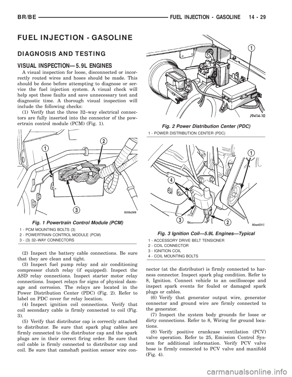
(1) Verify that the three 32±way electrical connec-
tors are fully inserted into the connector of the pow-
ertrain control module (PCM) (Fig. 1).
(2) Inspect the battery cable connections. Be sure
that they are clean and tight.
(3) Inspect fuel pump relay and air conditioning
compressor clutch relay (if equipped). Inspect the
ASD relay connections. Inspect starter motor relay
connections. Inspect relays for signs of physical dam-
age and corrosion. The relays are located in the
Power Distribution Center (PDC) (Fig. 2). Refer to
label on PDC cover for relay location.
(4) Inspect ignition coil connections. Verify that
coil secondary cable is firmly connected to coil (Fig.
3).
(5) Verify that distributor cap is correctly attached
to distributor. Be sure that spark plug cables are
firmly connected to the distributor cap and the spark
plugs are in their correct firing order. Be sure that
coil cable is firmly connected to distributor cap and
coil. Be sure that camshaft position sensor wire con-nector (at the distributor) is firmly connected to har-
ness connector. Inspect spark plug condition. Refer to
8, Ignition. Connect vehicle to an oscilloscope and
inspect spark events for fouled or damaged spark
plugs or cables.
(6) Verify that generator output wire, generator
connector and ground wire are firmly connected to
the generator.
(7) Inspect the system body grounds for loose or
dirty connections. Refer to 8, Wiring for ground loca-
tions.
(8) Verify positive crankcase ventilation (PCV)
valve operation. Refer to 25, Emission Control Sys-
tem for additional information. Verify PCV valve
hose is firmly connected to PCV valve and manifold
(Fig. 4).
Fig. 1 Powertrain Control Module (PCM)
1 - PCM MOUNTING BOLTS (3)
2 - POWERTRAIN CONTROL MODULE (PCM)
3 - (3) 32±WAY CONNECTORS
Fig. 2 Power Distribution Center (PDC)
1 - POWER DISTRIBUTION CENTER (PDC)
Fig. 3 Ignition CoilÐ5.9L EnginesÐTypical
1 - ACCESSORY DRIVE BELT TENSIONER
2 - COIL CONNECTOR
3 - IGNITION COIL
4 - COIL MOUNTING BOLTS
BR/BEFUEL INJECTION - GASOLINE 14 - 29