2002 DODGE RAM turn signal
[x] Cancel search: turn signalPage 1376 of 2255
FUEL INJECTION PUMP DATA
PLATE
SPECIFICATIONS
FUEL INJECTION PUMP DATA PLATE
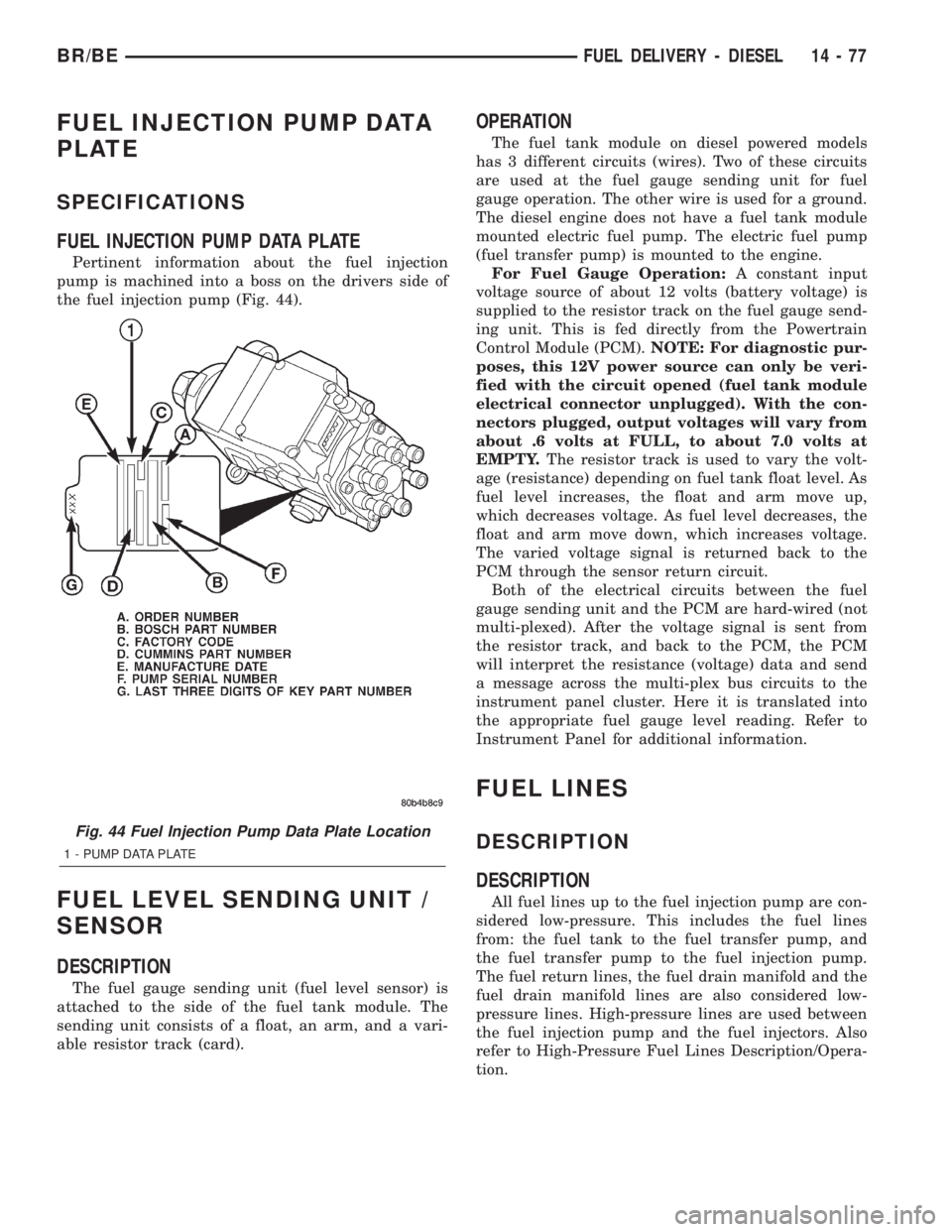
Pertinent information about the fuel injection
pump is machined into a boss on the drivers side of
the fuel injection pump (Fig. 44).
FUEL LEVEL SENDING UNIT /
SENSOR
DESCRIPTION
The fuel gauge sending unit (fuel level sensor) is
attached to the side of the fuel tank module. The
sending unit consists of a float, an arm, and a vari-
able resistor track (card).
OPERATION
The fuel tank module on diesel powered models
has 3 different circuits (wires). Two of these circuits
are used at the fuel gauge sending unit for fuel
gauge operation. The other wire is used for a ground.
The diesel engine does not have a fuel tank module
mounted electric fuel pump. The electric fuel pump
(fuel transfer pump) is mounted to the engine.
For Fuel Gauge Operation:A constant input
voltage source of about 12 volts (battery voltage) is
supplied to the resistor track on the fuel gauge send-
ing unit. This is fed directly from the Powertrain
Control Module (PCM).NOTE: For diagnostic pur-
poses, this 12V power source can only be veri-
fied with the circuit opened (fuel tank module
electrical connector unplugged). With the con-
nectors plugged, output voltages will vary from
about .6 volts at FULL, to about 7.0 volts at
EMPTY.The resistor track is used to vary the volt-
age (resistance) depending on fuel tank float level. As
fuel level increases, the float and arm move up,
which decreases voltage. As fuel level decreases, the
float and arm move down, which increases voltage.
The varied voltage signal is returned back to the
PCM through the sensor return circuit.
Both of the electrical circuits between the fuel
gauge sending unit and the PCM are hard-wired (not
multi-plexed). After the voltage signal is sent from
the resistor track, and back to the PCM, the PCM
will interpret the resistance (voltage) data and send
a message across the multi-plex bus circuits to the
instrument panel cluster. Here it is translated into
the appropriate fuel gauge level reading. Refer to
Instrument Panel for additional information.
FUEL LINES
DESCRIPTION
DESCRIPTION
All fuel lines up to the fuel injection pump are con-
sidered low-pressure. This includes the fuel lines
from: the fuel tank to the fuel transfer pump, and
the fuel transfer pump to the fuel injection pump.
The fuel return lines, the fuel drain manifold and the
fuel drain manifold lines are also considered low-
pressure lines. High-pressure lines are used between
the fuel injection pump and the fuel injectors. Also
refer to High-Pressure Fuel Lines Description/Opera-
tion.
Fig. 44 Fuel Injection Pump Data Plate Location
1 - PUMP DATA PLATE
BR/BEFUEL DELIVERY - DIESEL 14 - 77
Page 1388 of 2255
WATER IN FUEL SENSOR
DESCRIPTION
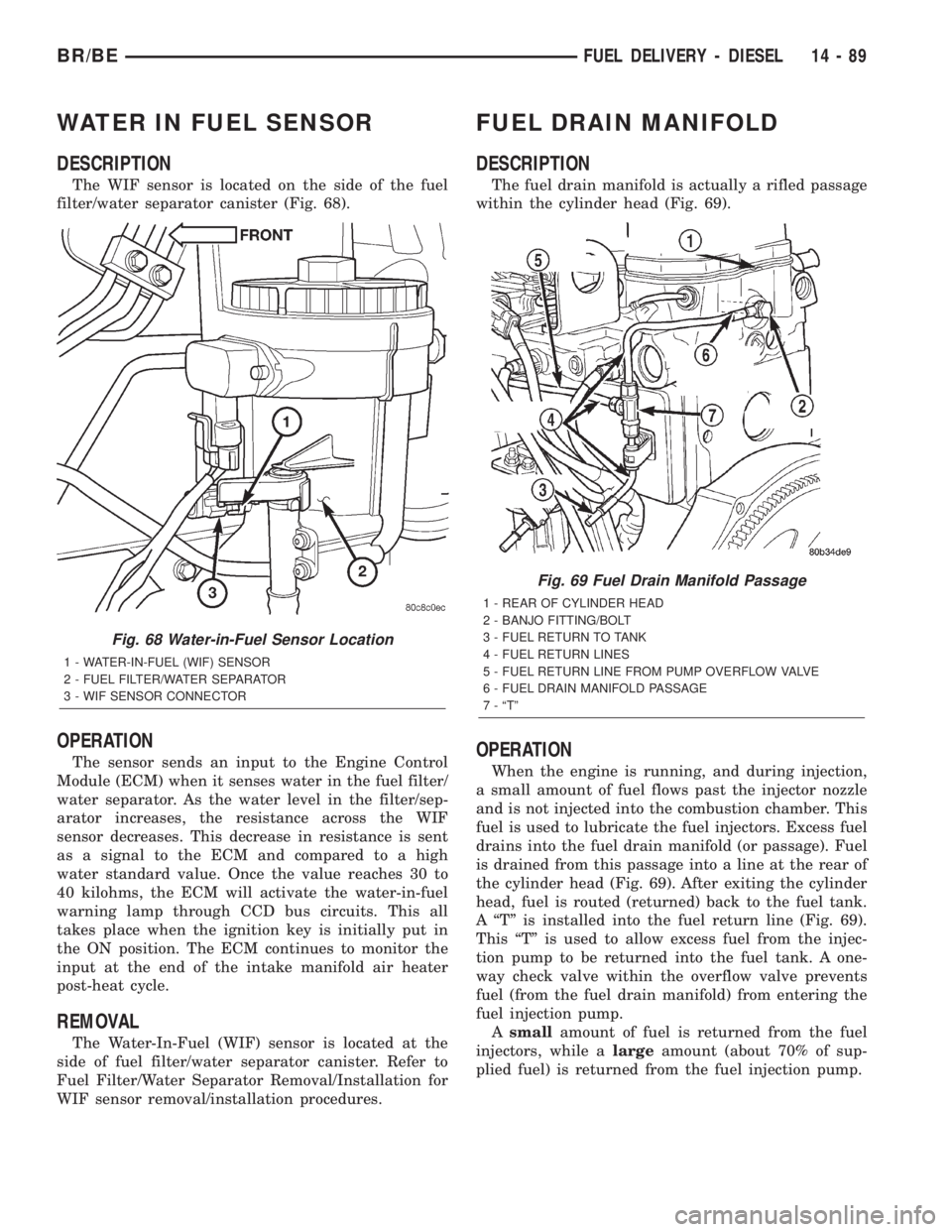
The WIF sensor is located on the side of the fuel
filter/water separator canister (Fig. 68).
OPERATION
The sensor sends an input to the Engine Control
Module (ECM) when it senses water in the fuel filter/
water separator. As the water level in the filter/sep-
arator increases, the resistance across the WIF
sensor decreases. This decrease in resistance is sent
as a signal to the ECM and compared to a high
water standard value. Once the value reaches 30 to
40 kilohms, the ECM will activate the water-in-fuel
warning lamp through CCD bus circuits. This all
takes place when the ignition key is initially put in
the ON position. The ECM continues to monitor the
input at the end of the intake manifold air heater
post-heat cycle.
REMOVAL
The Water-In-Fuel (WIF) sensor is located at the
side of fuel filter/water separator canister. Refer to
Fuel Filter/Water Separator Removal/Installation for
WIF sensor removal/installation procedures.
FUEL DRAIN MANIFOLD
DESCRIPTION
The fuel drain manifold is actually a rifled passage
within the cylinder head (Fig. 69).
OPERATION
When the engine is running, and during injection,
a small amount of fuel flows past the injector nozzle
and is not injected into the combustion chamber. This
fuel is used to lubricate the fuel injectors. Excess fuel
drains into the fuel drain manifold (or passage). Fuel
is drained from this passage into a line at the rear of
the cylinder head (Fig. 69). After exiting the cylinder
head, fuel is routed (returned) back to the fuel tank.
A ªTº is installed into the fuel return line (Fig. 69).
This ªTº is used to allow excess fuel from the injec-
tion pump to be returned into the fuel tank. A one-
way check valve within the overflow valve prevents
fuel (from the fuel drain manifold) from entering the
fuel injection pump.
Asmallamount of fuel is returned from the fuel
injectors, while alargeamount (about 70% of sup-
plied fuel) is returned from the fuel injection pump.
Fig. 68 Water-in-Fuel Sensor Location
1 - WATER-IN-FUEL (WIF) SENSOR
2 - FUEL FILTER/WATER SEPARATOR
3 - WIF SENSOR CONNECTOR
Fig. 69 Fuel Drain Manifold Passage
1 - REAR OF CYLINDER HEAD
2 - BANJO FITTING/BOLT
3 - FUEL RETURN TO TANK
4 - FUEL RETURN LINES
5 - FUEL RETURN LINE FROM PUMP OVERFLOW VALVE
6 - FUEL DRAIN MANIFOLD PASSAGE
7 - ªTº
BR/BEFUEL DELIVERY - DIESEL 14 - 89
Page 1417 of 2255
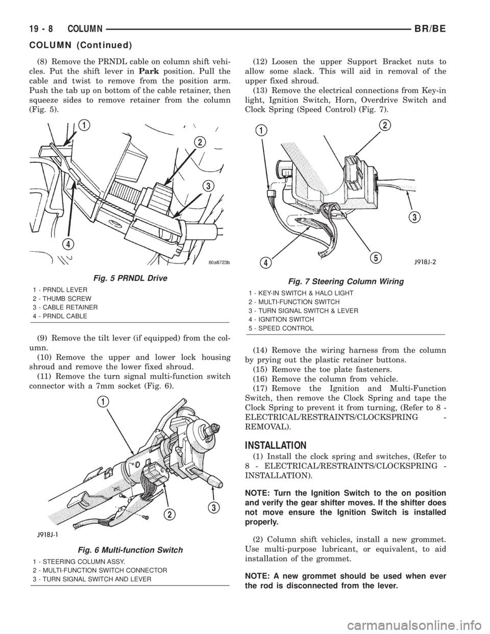
(8) Remove the PRNDL cable on column shift vehi-
cles. Put the shift lever inParkposition. Pull the
cable and twist to remove from the position arm.
Push the tab up on bottom of the cable retainer, then
squeeze sides to remove retainer from the column
(Fig. 5).
(9) Remove the tilt lever (if equipped) from the col-
umn.
(10) Remove the upper and lower lock housing
shroud and remove the lower fixed shroud.
(11) Remove the turn signal multi-function switch
connector with a 7mm socket (Fig. 6).(12) Loosen the upper Support Bracket nuts to
allow some slack. This will aid in removal of the
upper fixed shroud.
(13) Remove the electrical connections from Key-in
light, Ignition Switch, Horn, Overdrive Switch and
Clock Spring (Speed Control) (Fig. 7).
(14) Remove the wiring harness from the column
by prying out the plastic retainer buttons.
(15) Remove the toe plate fasteners.
(16) Remove the column from vehicle.
(17) Remove the Ignition and Multi-Function
Switch, then remove the Clock Spring and tape the
Clock Spring to prevent it from turning, (Refer to 8 -
ELECTRICAL/RESTRAINTS/CLOCKSPRING -
REMOVAL).
INSTALLATION
(1) Install the clock spring and switches, (Refer to
8 - ELECTRICAL/RESTRAINTS/CLOCKSPRING -
INSTALLATION).
NOTE: Turn the Ignition Switch to the on position
and verify the gear shifter moves. If the shifter does
not move ensure the Ignition Switch is installed
properly.
(2) Column shift vehicles, install a new grommet.
Use multi-purpose lubricant, or equivalent, to aid
installation of the grommet.
NOTE: A new grommet should be used when ever
the rod is disconnected from the lever.
Fig. 5 PRNDL Drive
1 - PRNDL LEVER
2 - THUMB SCREW
3 - CABLE RETAINER
4 - PRNDL CABLE
Fig. 6 Multi-function Switch
1 - STEERING COLUMN ASSY.
2 - MULTI-FUNCTION SWITCH CONNECTOR
3 - TURN SIGNAL SWITCH AND LEVER
Fig. 7 Steering Column Wiring
1 - KEY-IN SWITCH & HALO LIGHT
2 - MULTI-FUNCTION SWITCH
3 - TURN SIGNAL SWITCH & LEVER
4 - IGNITION SWITCH
5 - SPEED CONTROL
19 - 8 COLUMNBR/BE
COLUMN (Continued)
Page 1421 of 2255
REMOVAL
(1) Remove the key lock cylinder.
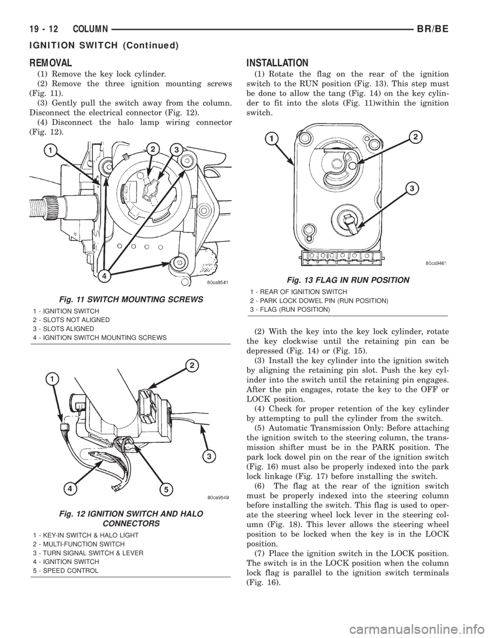
(2) Remove the three ignition mounting screws
(Fig. 11).
(3) Gently pull the switch away from the column.
Disconnect the electrical connector (Fig. 12).
(4) Disconnect the halo lamp wiring connector
(Fig. 12).
INSTALLATION
(1) Rotate the flag on the rear of the ignition
switch to the RUN position (Fig. 13). This step must
be done to allow the tang (Fig. 14) on the key cylin-
der to fit into the slots (Fig. 11)within the ignition
switch.
(2) With the key into the key lock cylinder, rotate
the key clockwise until the retaining pin can be
depressed (Fig. 14) or (Fig. 15).
(3) Install the key cylinder into the ignition switch
by aligning the retaining pin slot. Push the key cyl-
inder into the switch until the retaining pin engages.
After the pin engages, rotate the key to the OFF or
LOCK position.
(4) Check for proper retention of the key cylinder
by attempting to pull the cylinder from the switch.
(5) Automatic Transmission Only: Before attaching
the ignition switch to the steering column, the trans-
mission shifter must be in the PARK position. The
park lock dowel pin on the rear of the ignition switch
(Fig. 16) must also be properly indexed into the park
lock linkage (Fig. 17) before installing the switch.
(6) The flag at the rear of the ignition switch
must be properly indexed into the steering column
before installing the switch. This flag is used to oper-
ate the steering wheel lock lever in the steering col-
umn (Fig. 18). This lever allows the steering wheel
position to be locked when the key is in the LOCK
position.
(7) Place the ignition switch in the LOCK position.
The switch is in the LOCK position when the column
lock flag is parallel to the ignition switch terminals
(Fig. 16).
Fig. 11 SWITCH MOUNTING SCREWS
1 - IGNITION SWITCH
2 - SLOTS NOT ALIGNED
3 - SLOTS ALIGNED
4 - IGNITION SWITCH MOUNTING SCREWS
Fig. 12 IGNITION SWITCH AND HALO
CONNECTORS
1 - KEY-IN SWITCH & HALO LIGHT
2 - MULTI-FUNCTION SWITCH
3 - TURN SIGNAL SWITCH & LEVER
4 - IGNITION SWITCH
5 - SPEED CONTROL
Fig. 13 FLAG IN RUN POSITION
1 - REAR OF IGNITION SWITCH
2 - PARK LOCK DOWEL PIN (RUN POSITION)
3 - FLAG (RUN POSITION)
19 - 12 COLUMNBR/BE
IGNITION SWITCH (Continued)
Page 1606 of 2255
GOVERNOR PRESSURE CURVES
There are four governor pressure curves pro-
grammed into the transmission control module. The
different curves allow the control module to adjust
governor pressure for varying conditions. One curve
is used for operation when fluid temperature is at, or
below, ±1ÉC (30ÉF). A second curve is used when fluid
temperature is at, or above, 10ÉC (50ÉF) during nor-
mal city or highway driving. A third curve is used
during wide-open throttle operation. The fourth curve
is used when driving with the transfer case in low
range.
OPERATION
Compensation is required for performance varia-
tions of two of the input devices. Though the slope of
the transfer functions is tightly controlled, offset may
vary due to various environmental factors or manu-
facturing tolerances.
The pressure transducer is affected by barometric
pressure as well as temperature. Calibration of the
zero pressure offset is required to compensate for
shifting output due to these factors.
Normal calibration will be performed when sump
temperature is above 50 degrees F, or in the absence
of sump temperature data, after the first 10 minutes
of vehicle operation. Calibration of the pressure
transducer offset occurs each time the output shaft
speed falls below 200 RPM. Calibration shall be
repeated each 3 seconds the output shaft speed is
below 200 RPM. A 0.5 second pulse of 95% duty cycle
is applied to the governor pressure solenoid valve
and the transducer output is read during this pulse.
Averaging of the transducer signal is necessary to
reject electrical noise.
Under cold conditions (below 50 degrees F sump),
the governor pressure solenoid valve response may
be too slow to guarantee 0 psi during the 0.5 second
calibration pulse. Calibration pulses are continued
during this period, however the transducer output
valves are discarded. Transducer offset must be read
at key-on, under conditions which promote a stable
reading. This value is retained and becomes the off-
set during the9cold9period of operation.
GOVERNOR PRESSURE SOLENOID VALVE
The inlet side of the solenoid valve is exposed to
normal transmission line pressure. The outlet side of
the valve leads to the valve body governor circuit.
The solenoid valve regulates line pressure to pro-
duce governor pressure. The average current sup-
plied to the solenoid controls governor pressure. One
amp current produces zero kPa/psi governor pres-
sure. Zero amps sets the maximum governor pres-
sure.The powertrain control module (PCM) turns on the
trans control relay which supplies electrical power to
the solenoid valve. Operating voltage is 12 volts
(DC). The PCM controls the ground side of the sole-
noid using the governor pressure solenoid control cir-
cuit.
GOVERNOR PRESSURE SENSOR
The sensor output signal provides the necessary
feedback to the PCM. This feedback is needed to ade-
quately control governor pressure.
GOVERNOR BODY AND TRANSFER PLATE
The transfer plate channels line pressure to the
solenoid valve through the governor body. It also
channels governor pressure from the solenoid valve
to the governor circuit. It is the solenoid valve that
develops the necessary governor pressure.
GOVERNOR PRESSURE CURVES
LOW TRANSMISSION FLUID TEMPERATURE
When the transmission fluid is cold the conven-
tional governor can delay shifts, resulting in higher
than normal shift speeds and harsh shifts. The elec-
tronically controlled low temperature governor pres-
sure curve is higher than normal to make the
transmission shift at normal speeds and sooner. The
PCM uses a temperature sensor in the transmission
oil sump to determine when low temperature gover-
nor pressure is needed.
NORMAL OPERATION
Normal operation is refined through the increased
computing power of the PCM and through access to
data on engine operating conditions provided by the
PCM that were not available with the previous
stand-alone electronic module. This facilitated the
development of a load adaptive shift strategy - the
ability to alter the shift schedule in response to vehi-
cle load condition. One manifestation of this capabil-
ity is grade9hunting9prevention - the ability of the
transmission logic to delay an upshift on a grade if
the engine does not have sufficient power to main-
tain speed in the higher gear. The 3-2 downshift and
the potential for hunting between gears occurs with a
heavily loaded vehicle or on steep grades. When
hunting occurs, it is very objectionable because shifts
are frequent and accompanied by large changes in
noise and acceleration.
WIDE OPEN THROTTLE OPERATION
In wide-open throttle (WOT) mode, adaptive mem-
ory in the PCM assures that up-shifts occur at the
preprogrammed optimum speed. WOT operation is
determined from the throttle position sensor, which
is also a part of the emission control system. The ini-
BR/BEAUTOMATIC TRANSMISSION - 46RE 21 - 153
ELECTRONIC GOVERNOR (Continued)
Page 1643 of 2255
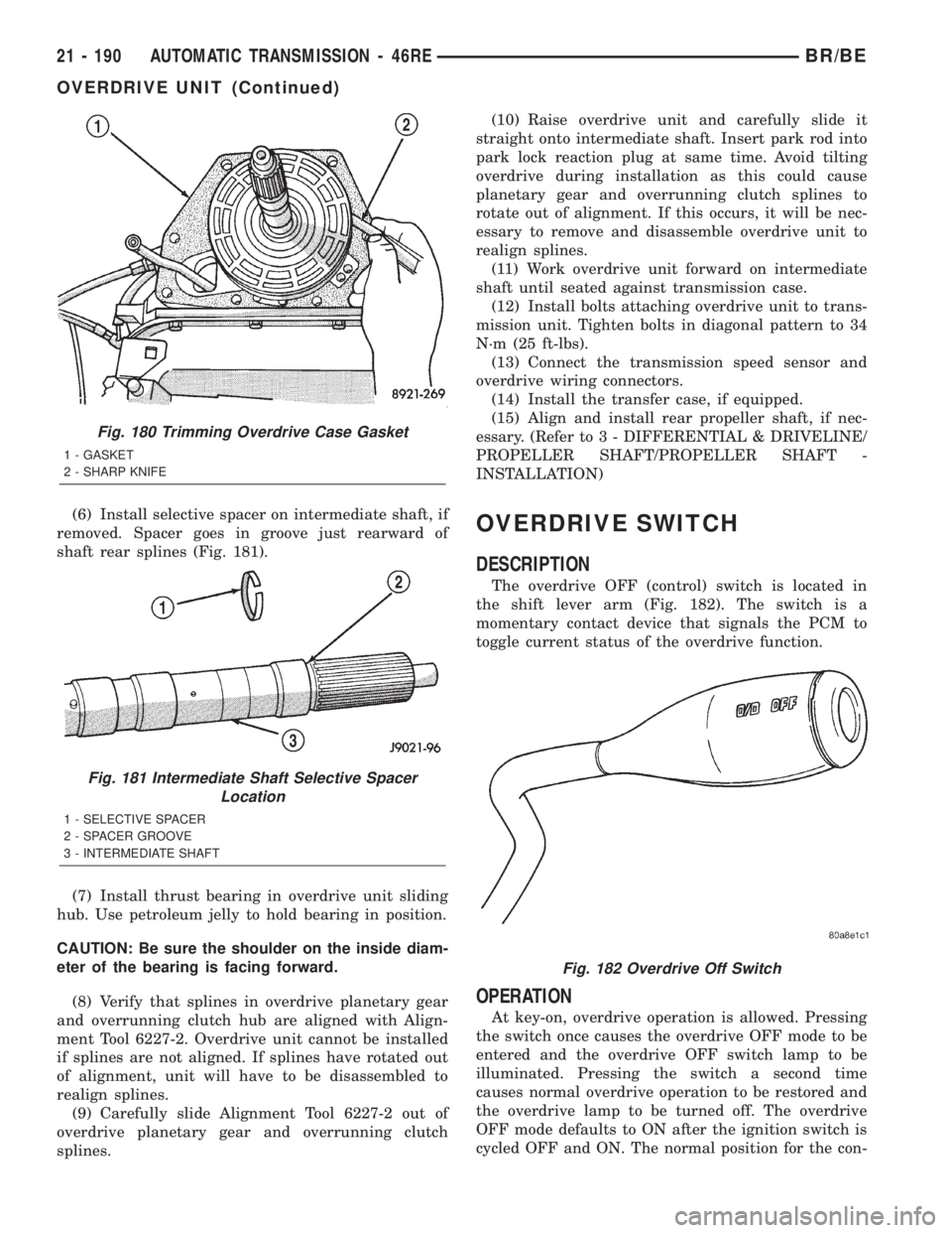
(6) Install selective spacer on intermediate shaft, if
removed. Spacer goes in groove just rearward of
shaft rear splines (Fig. 181).
(7) Install thrust bearing in overdrive unit sliding
hub. Use petroleum jelly to hold bearing in position.
CAUTION: Be sure the shoulder on the inside diam-
eter of the bearing is facing forward.
(8) Verify that splines in overdrive planetary gear
and overrunning clutch hub are aligned with Align-
ment Tool 6227-2. Overdrive unit cannot be installed
if splines are not aligned. If splines have rotated out
of alignment, unit will have to be disassembled to
realign splines.
(9) Carefully slide Alignment Tool 6227-2 out of
overdrive planetary gear and overrunning clutch
splines.(10) Raise overdrive unit and carefully slide it
straight onto intermediate shaft. Insert park rod into
park lock reaction plug at same time. Avoid tilting
overdrive during installation as this could cause
planetary gear and overrunning clutch splines to
rotate out of alignment. If this occurs, it will be nec-
essary to remove and disassemble overdrive unit to
realign splines.
(11) Work overdrive unit forward on intermediate
shaft until seated against transmission case.
(12) Install bolts attaching overdrive unit to trans-
mission unit. Tighten bolts in diagonal pattern to 34
N´m (25 ft-lbs).
(13) Connect the transmission speed sensor and
overdrive wiring connectors.
(14) Install the transfer case, if equipped.
(15) Align and install rear propeller shaft, if nec-
essary. (Refer to 3 - DIFFERENTIAL & DRIVELINE/
PROPELLER SHAFT/PROPELLER SHAFT -
INSTALLATION)OVERDRIVE SWITCH
DESCRIPTION
The overdrive OFF (control) switch is located in
the shift lever arm (Fig. 182). The switch is a
momentary contact device that signals the PCM to
toggle current status of the overdrive function.
OPERATION
At key-on, overdrive operation is allowed. Pressing
the switch once causes the overdrive OFF mode to be
entered and the overdrive OFF switch lamp to be
illuminated. Pressing the switch a second time
causes normal overdrive operation to be restored and
the overdrive lamp to be turned off. The overdrive
OFF mode defaults to ON after the ignition switch is
cycled OFF and ON. The normal position for the con-
Fig. 180 Trimming Overdrive Case Gasket
1 - GASKET
2 - SHARP KNIFE
Fig. 181 Intermediate Shaft Selective Spacer
Location
1 - SELECTIVE SPACER
2 - SPACER GROOVE
3 - INTERMEDIATE SHAFT
Fig. 182 Overdrive Off Switch
21 - 190 AUTOMATIC TRANSMISSION - 46REBR/BE
OVERDRIVE UNIT (Continued)
Page 1662 of 2255
noid valve is defined as a valve which does not allow
hydraulic flow when no current or voltage is applied
to the solenoid. These valves perform hydraulic con-
trol functions for the transmission and must there-
fore be durable and tolerant of dirt particles. For
these reasons, the valves have hardened steel pop-
pets and ball valves. The solenoids operate the valves
directly, which means that the solenoids must have
very high outputs to close the valves against the siz-
able flow areas and line pressures found in current
transmissions. Fast response time is also necessary
to ensure accurate control of the transmission.
The strength of the magnetic field is the primary
force that determines the speed of operation in a par-
ticular solenoid design. A stronger magnetic field will
cause the plunger to move at a greater speed than a
weaker one. There are basically two ways to increase
the force of the magnetic field:
²Increase the amount of current applied to the
coil or
²Increase the number of turns of wire in the coil.
The most common practice is to increase the num-
ber of turns by using thin wire that can completely
fill the available space within the solenoid housing.
The strength of the spring and the length of the
plunger also contribute to the response speed possi-
ble by a particular solenoid design.
A solenoid can also be described by the method by
which it is controlled. Some of the possibilities
include variable force, pulse-width modulated, con-
stant ON, or duty cycle. The variable force and pulse-
width modulated versions utilize similar methods to
control the current flow through the solenoid to posi-
tion the solenoid plunger at a desired position some-
where between full ON and full OFF. The constant
ON and duty cycled versions control the voltage
across the solenoid to allow either full flow or no flow
through the solenoid's valve.
OPERATION
When an electrical current is applied to the sole-
noid coil, a magnetic field is created which produces
an attraction to the plunger, causing the plunger to
move and work against the spring pressure and the
load applied by the fluid the valve is controlling. The
plunger is normally directly attached to the valve
which it is to operate. When the current is removed
from the coil, the attraction is removed and the
plunger will return to its original position due to
spring pressure.
The plunger is made of a conductive material and
accomplishes this movement by providing a path for
the magnetic field to flow. By keeping the air gap
between the plunger and the coil to the minimum
necessary to allow free movement of the plunger, the
magnetic field is maximized.
SPEED SENSOR
DESCRIPTION
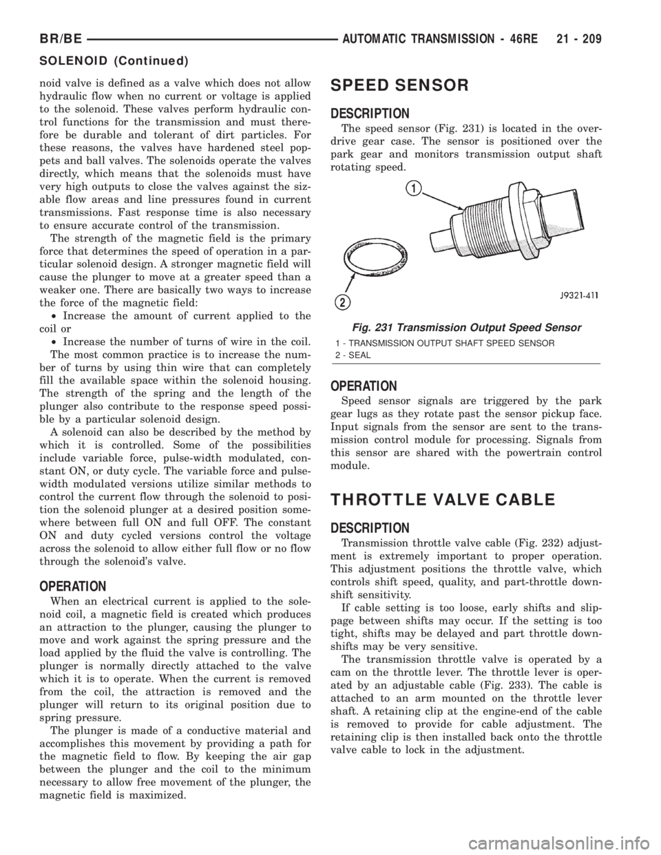
The speed sensor (Fig. 231) is located in the over-
drive gear case. The sensor is positioned over the
park gear and monitors transmission output shaft
rotating speed.
OPERATION
Speed sensor signals are triggered by the park
gear lugs as they rotate past the sensor pickup face.
Input signals from the sensor are sent to the trans-
mission control module for processing. Signals from
this sensor are shared with the powertrain control
module.
THROTTLE VALVE CABLE
DESCRIPTION
Transmission throttle valve cable (Fig. 232) adjust-
ment is extremely important to proper operation.
This adjustment positions the throttle valve, which
controls shift speed, quality, and part-throttle down-
shift sensitivity.
If cable setting is too loose, early shifts and slip-
page between shifts may occur. If the setting is too
tight, shifts may be delayed and part throttle down-
shifts may be very sensitive.
The transmission throttle valve is operated by a
cam on the throttle lever. The throttle lever is oper-
ated by an adjustable cable (Fig. 233). The cable is
attached to an arm mounted on the throttle lever
shaft. A retaining clip at the engine-end of the cable
is removed to provide for cable adjustment. The
retaining clip is then installed back onto the throttle
valve cable to lock in the adjustment.
Fig. 231 Transmission Output Speed Sensor
1 - TRANSMISSION OUTPUT SHAFT SPEED SENSOR
2 - SEAL
BR/BEAUTOMATIC TRANSMISSION - 46RE 21 - 209
SOLENOID (Continued)
Page 1776 of 2255
temperature is at, or above, 10ÉC (50ÉF) during nor-
mal city or highway driving. A third curve is used
during wide-open throttle operation. The fourth curve
is used when driving with the transfer case in low
range.
OPERATION
Compensation is required for performance varia-
tions of two of the input devices. Though the slope of
the transfer functions is tightly controlled, offset may
vary due to various environmental factors or manu-
facturing tolerances.
The pressure transducer is affected by barometric
pressure as well as temperature. Calibration of the
zero pressure offset is required to compensate for
shifting output due to these factors.
Normal calibration will be performed when sump
temperature is above 50 degrees F, or in the absence
of sump temperature data, after the first 10 minutes
of vehicle operation. Calibration of the pressure
transducer offset occurs each time the output shaft
speed falls below 200 RPM. Calibration shall be
repeated each 3 seconds the output shaft speed is
below 200 RPM. A 0.5 second pulse of 95% duty cycle
is applied to the governor pressure solenoid valve
and the transducer output is read during this pulse.
Averaging of the transducer signal is necessary to
reject electrical noise.
Under cold conditions (below 50 degrees F sump),
the governor pressure solenoid valve response may
be too slow to guarantee 0 psi during the 0.5 second
calibration pulse. Calibration pulses are continued
during this period, however the transducer output
valves are discarded. Transducer offset must be read
at key-on, under conditions which promote a stable
reading. This value is retained and becomes the off-
set during the9cold9period of operation.
GOVERNOR PRESSURE SOLENOID VALVE
The inlet side of the solenoid valve is exposed to
normal transmission line pressure. The outlet side of
the valve leads to the valve body governor circuit.
The solenoid valve regulates line pressure to pro-
duce governor pressure. The average current sup-
plied to the solenoid controls governor pressure. One
amp current produces zero kPa/psi governor pres-
sure. Zero amps sets the maximum governor pres-
sure.
The powertrain control module (PCM) turns on the
trans control relay which supplies electrical power to
the solenoid valve. Operating voltage is 12 volts
(DC). The PCM controls the ground side of the sole-
noid using the governor pressure solenoid control cir-
cuit.
GOVERNOR PRESSURE SENSOR
The sensor output signal provides the necessary
feedback to the PCM. This feedback is needed to ade-
quately control governor pressure.
GOVERNOR BODY AND TRANSFER PLATE
The transfer plate channels line pressure to the
solenoid valve through the governor body. It also
channels governor pressure from the solenoid valve
to the governor circuit. It is the solenoid valve that
develops the necessary governor pressure.
GOVERNOR PRESSURE CURVES
LOW TRANSMISSION FLUID TEMPERATURE
When the transmission fluid is cold the conven-
tional governor can delay shifts, resulting in higher
than normal shift speeds and harsh shifts. The elec-
tronically controlled low temperature governor pres-
sure curve is higher than normal to make the
transmission shift at normal speeds and sooner. The
PCM uses a temperature sensor in the transmission
oil sump to determine when low temperature gover-
nor pressure is needed.
NORMAL OPERATION
Normal operation is refined through the increased
computing power of the PCM and through access to
data on engine operating conditions provided by the
PCM that were not available with the previous
stand-alone electronic module. This facilitated the
development of a load adaptive shift strategy - the
ability to alter the shift schedule in response to vehi-
cle load condition. One manifestation of this capabil-
ity is grade9hunting9prevention - the ability of the
transmission logic to delay an upshift on a grade if
the engine does not have sufficient power to main-
tain speed in the higher gear. The 3-2 downshift and
the potential for hunting between gears occurs with a
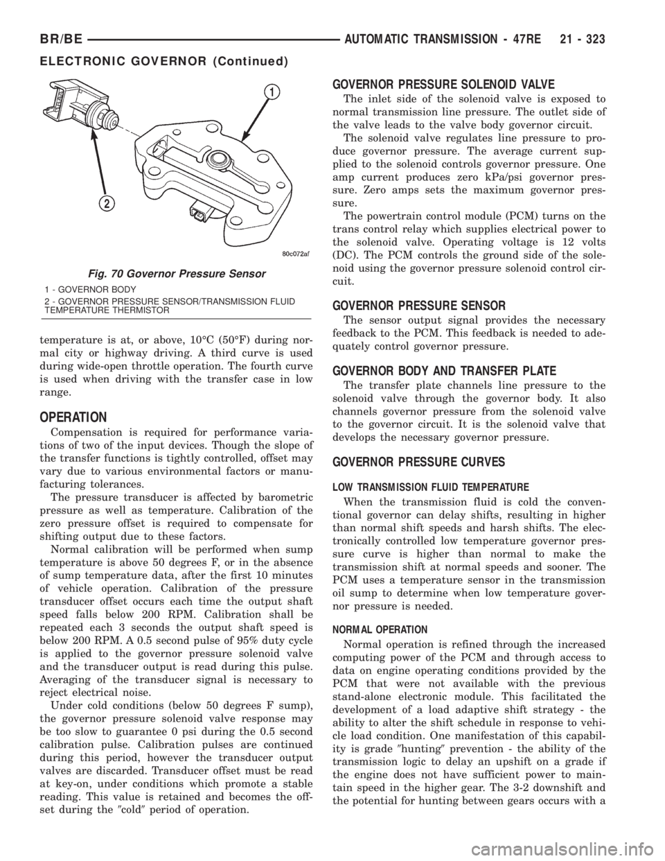
Fig. 70 Governor Pressure Sensor
1 - GOVERNOR BODY
2 - GOVERNOR PRESSURE SENSOR/TRANSMISSION FLUID
TEMPERATURE THERMISTOR
BR/BEAUTOMATIC TRANSMISSION - 47RE 21 - 323
ELECTRONIC GOVERNOR (Continued)