Page 1618 of 2399
INSTALLATION
(1) Install transaxle assembly to engine using a
transmission jack and helper.
(2) Install and torque transaxle-to-engine bolts to
95 N´m (70 ft. lbs.).
(3) Using screw jack and wood block, raise engine/
transaxle assembly into position and install left
upper mount thru-bolt (Fig. 97). Torque bolt to 75
N´m (55 ft. lbs.).
(4) Install left wheel splash shield.
(5) Install torque converter-to-drive plate bolts and
torque to 88 N´m (65 ft. lbs.).
(6) Install rear mount bracket to transaxle (Fig.
98). Install bolts by hand but do not tighten at this
time.
(7) Align rear mount bracket to mount and install
thru-bolt. Do not tighten at this time.
(8) Connect vehicle speed sensor connector.
Fig. 97 Left Mount-to-Rail
1 - FRAME BRACKET
2 - FRAME RAIL - LEFT
3 - BOLT
4 - TRANSAXLE MOUNT
Fig. 98 Rear Mount Bracket
1 - BOLT - VERTICAL
2 - BRACKET - REAR MOUNT3 - BOLT - HORIZONTAL
RS31TH AUTOMATIC TRANSAXLE21-61
31TH AUTOMATIC TRANSAXLE (Continued)
ProCarManuals.com
Page 1623 of 2399
Drive (Third) Not Locked Up
21 - 66 31TH AUTOMATIC TRANSAXLERS
31TH AUTOMATIC TRANSAXLE (Continued)
ProCarManuals.com
Page 1624 of 2399
Drive (Third) Lock-Up
RS31TH AUTOMATIC TRANSAXLE21-67
31TH AUTOMATIC TRANSAXLE (Continued)
ProCarManuals.com
Page 1631 of 2399

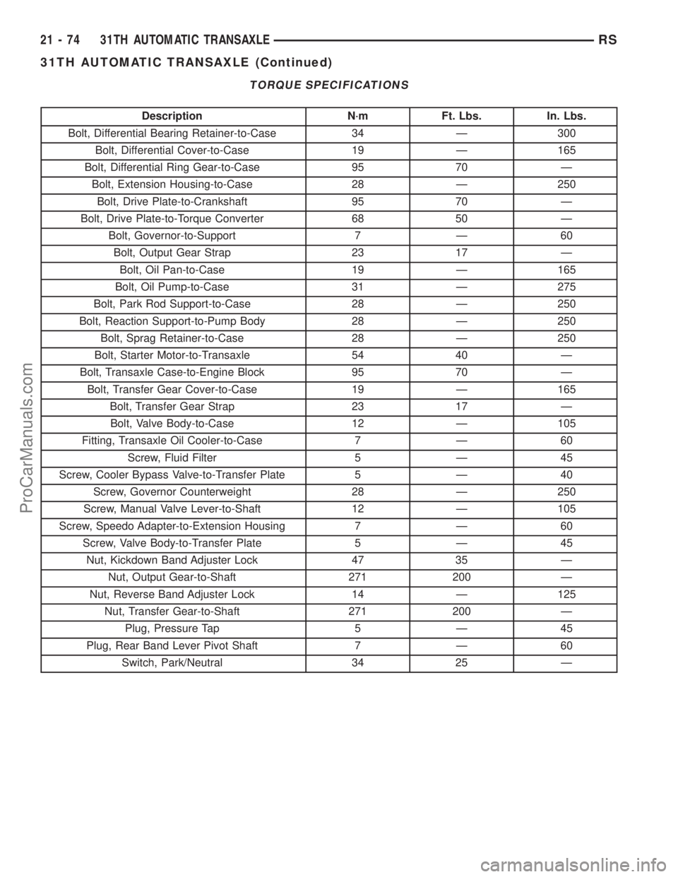
TORQUE SPECIFICATIONS
Description N´m Ft. Lbs. In. Lbs.
Bolt, Differential Bearing Retainer-to-Case 34 Ð 300
Bolt, Differential Cover-to-Case 19 Ð 165
Bolt, Differential Ring Gear-to-Case 95 70 Ð
Bolt, Extension Housing-to-Case 28 Ð 250
Bolt, Drive Plate-to-Crankshaft 95 70 Ð
Bolt, Drive Plate-to-Torque Converter 68 50 Ð
Bolt, Governor-to-Support 7 Ð 60
Bolt, Output Gear Strap 23 17 Ð
Bolt, Oil Pan-to-Case 19 Ð 165
Bolt, Oil Pump-to-Case 31 Ð 275
Bolt, Park Rod Support-to-Case 28 Ð 250
Bolt, Reaction Support-to-Pump Body 28 Ð 250
Bolt, Sprag Retainer-to-Case 28 Ð 250
Bolt, Starter Motor-to-Transaxle 54 40 Ð
Bolt, Transaxle Case-to-Engine Block 95 70 Ð
Bolt, Transfer Gear Cover-to-Case 19 Ð 165
Bolt, Transfer Gear Strap 23 17 Ð
Bolt, Valve Body-to-Case 12 Ð 105
Fitting, Transaxle Oil Cooler-to-Case 7 Ð 60
Screw, Fluid Filter 5 Ð 45
Screw, Cooler Bypass Valve-to-Transfer Plate 5 Ð 40
Screw, Governor Counterweight 28 Ð 250
Screw, Manual Valve Lever-to-Shaft 12 Ð 105
Screw, Speedo Adapter-to-Extension Housing 7 Ð 60
Screw, Valve Body-to-Transfer Plate 5 Ð 45
Nut, Kickdown Band Adjuster Lock 47 35 Ð
Nut, Output Gear-to-Shaft 271 200 Ð
Nut, Reverse Band Adjuster Lock 14 Ð 125
Nut, Transfer Gear-to-Shaft 271 200 Ð
Plug, Pressure Tap 5 Ð 45
Plug, Rear Band Lever Pivot Shaft 7 Ð 60
Switch, Park/Neutral 34 25 Ð
21 - 74 31TH AUTOMATIC TRANSAXLERS
31TH AUTOMATIC TRANSAXLE (Continued)
ProCarManuals.com
Page 1632 of 2399
SPECIAL TOOLS
31TH AUTOMATIC TRANSAXLE
Adapter Blocks C-293±45
Adapter Blocks C-293±52
Puller Press C-293±PA
Pressure Gauge (High) C-3293SP
Dial Indicator C-3339
Spring Compressor C-3575-A
Band Adjusting Adapter C-3705
Oil Pump Puller C-3752
Throttle Setting Gauge C-3763
Seal Puller C-3981B
RS31TH AUTOMATIC TRANSAXLE21-75
31TH AUTOMATIC TRANSAXLE (Continued)
ProCarManuals.com
Page 1637 of 2399

BANDS
DESCRIPTION
KICKDOWN (FRONT) BAND
DESCRIPTION
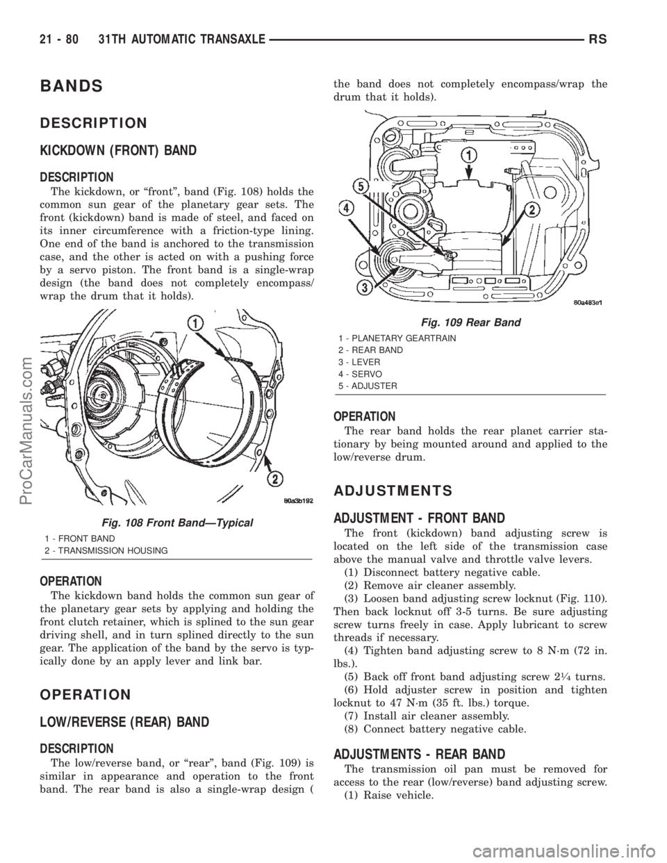
The kickdown, or ªfrontº, band (Fig. 108) holds the
common sun gear of the planetary gear sets. The
front (kickdown) band is made of steel, and faced on
its inner circumference with a friction-type lining.
One end of the band is anchored to the transmission
case, and the other is acted on with a pushing force
by a servo piston. The front band is a single-wrap
design (the band does not completely encompass/
wrap the drum that it holds).
OPERATION
The kickdown band holds the common sun gear of
the planetary gear sets by applying and holding the
front clutch retainer, which is splined to the sun gear
driving shell, and in turn splined directly to the sun
gear. The application of the band by the servo is typ-
ically done by an apply lever and link bar.
OPERATION
LOW/REVERSE (REAR) BAND
DESCRIPTION
The low/reverse band, or ªrearº, band (Fig. 109) is
similar in appearance and operation to the front
band. The rear band is also a single-wrap design (the band does not completely encompass/wrap the
drum that it holds).
OPERATION
The rear band holds the rear planet carrier sta-
tionary by being mounted around and applied to the
low/reverse drum.
ADJUSTMENTS
ADJUSTMENT - FRONT BAND
The front (kickdown) band adjusting screw is
located on the left side of the transmission case
above the manual valve and throttle valve levers.
(1) Disconnect battery negative cable.
(2) Remove air cleaner assembly.
(3) Loosen band adjusting screw locknut (Fig. 110).
Then back locknut off 3-5 turns. Be sure adjusting
screw turns freely in case. Apply lubricant to screw
threads if necessary.
(4) Tighten band adjusting screw to 8 N´m (72 in.
lbs.).
(5) Back off front band adjusting screw 2
1¤4turns.
(6) Hold adjuster screw in position and tighten
locknut to 47 N´m (35 ft. lbs.) torque.
(7) Install air cleaner assembly.
(8) Connect battery negative cable.
ADJUSTMENTS - REAR BAND
The transmission oil pan must be removed for
access to the rear (low/reverse) band adjusting screw.
(1) Raise vehicle.
Fig. 108 Front BandÐTypical
1 - FRONT BAND
2 - TRANSMISSION HOUSING
Fig. 109 Rear Band
1 - PLANETARY GEARTRAIN
2 - REAR BAND
3 - LEVER
4 - SERVO
5 - ADJUSTER
21 - 80 31TH AUTOMATIC TRANSAXLERS
ProCarManuals.com
Page 1638 of 2399

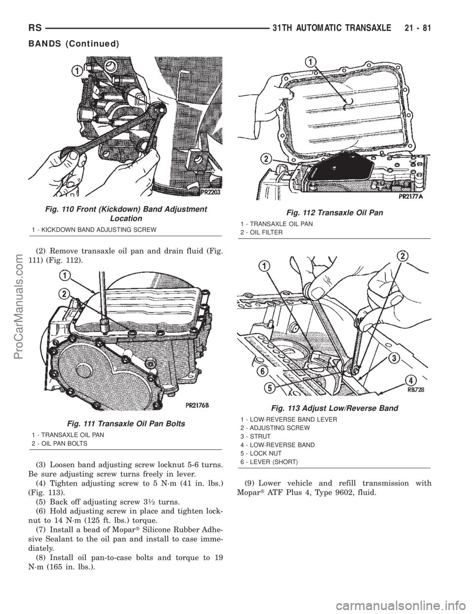
(2) Remove transaxle oil pan and drain fluid (Fig.
111) (Fig. 112).
(3) Loosen band adjusting screw locknut 5-6 turns.
Be sure adjusting screw turns freely in lever.
(4) Tighten adjusting screw to 5 N´m (41 in. lbs.)
(Fig. 113).
(5) Back off adjusting screw 3
1¤2turns.
(6) Hold adjusting screw in place and tighten lock-
nut to 14 N´m (125 ft. lbs.) torque.
(7) Install a bead of MopartSilicone Rubber Adhe-
sive Sealant to the oil pan and install to case imme-
diately.
(8) Install oil pan-to-case bolts and torque to 19
N´m (165 in. lbs.).(9) Lower vehicle and refill transmission with
MopartATF Plus 4, Type 9602, fluid.
Fig. 110 Front (Kickdown) Band Adjustment
Location
1 - KICKDOWN BAND ADJUSTING SCREW
Fig. 111 Transaxle Oil Pan Bolts
1 - TRANSAXLE OIL PAN
2 - OIL PAN BOLTS
Fig. 112 Transaxle Oil Pan
1 - TRANSAXLE OIL PAN
2 - OIL FILTER
Fig. 113 Adjust Low/Reverse Band
1 - LOW-REVERSE BAND LEVER
2 - ADJUSTING SCREW
3 - STRUT
4 - LOW-REVERSE BAND
5 - LOCK NUT
6 - LEVER (SHORT)
RS31TH AUTOMATIC TRANSAXLE21-81
BANDS (Continued)
ProCarManuals.com
Page 1661 of 2399

ADJUSTMENTS
GEARSHIFT CABLE ADJUSTMENT
Lift and rotate the gearshift hand lever into the
park (P) gate position and remove the ignition key.
This confirms the shift lever is in the gated park (P)
position.
After confirming the park gate position, turn the
ignition switch . If the starter will operate, the park
gate position is correct. Move the shift lever into the
neutral (N) position. If the starter will operate in this
position, the linkage is properly adjusted. If the
starter fails to operate in either position, linkage
adjustment is required.
(1) Park the vehicle on level ground and set the
parking brake.
(2) Place the gearshift lever in park (P) gate posi-
tion and remove key.
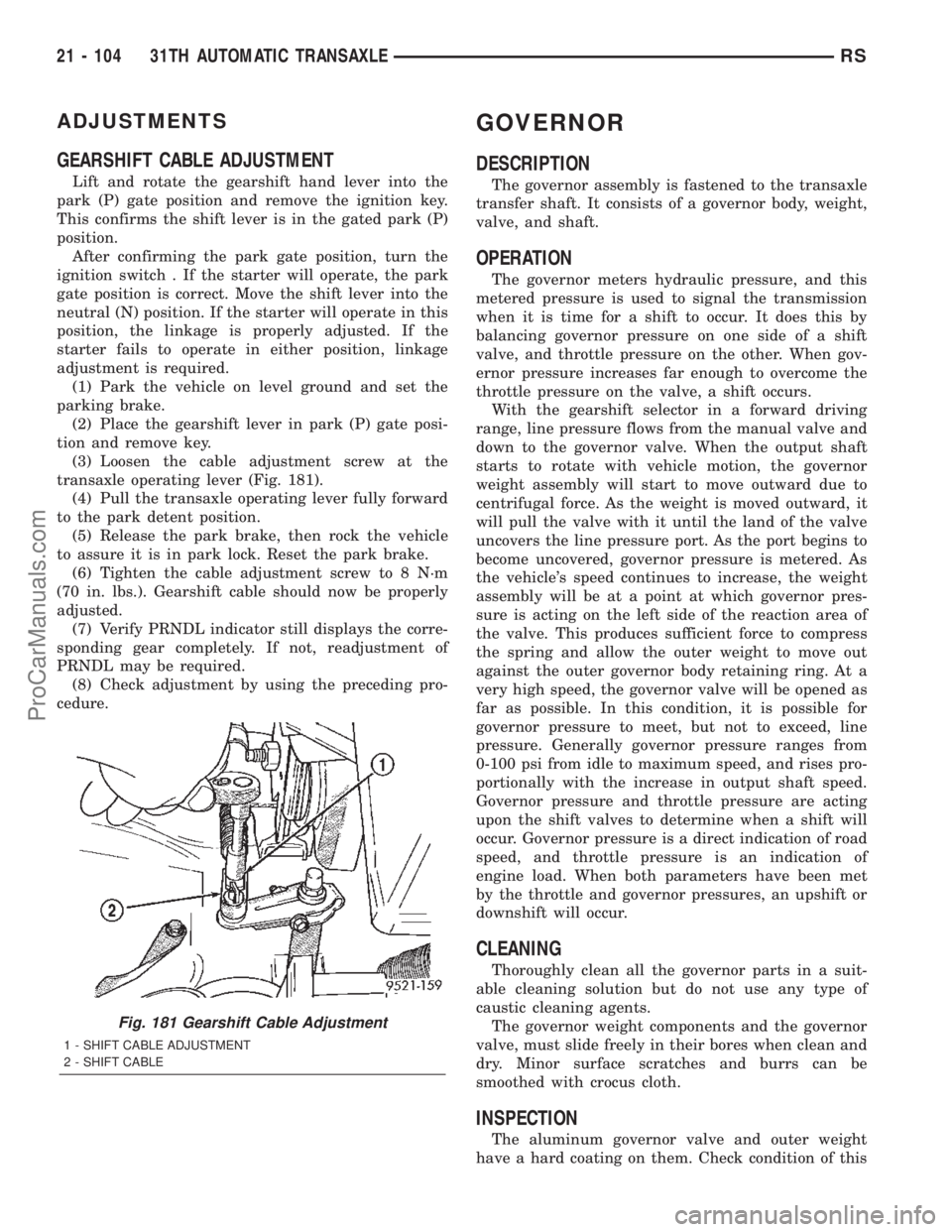
(3) Loosen the cable adjustment screw at the
transaxle operating lever (Fig. 181).
(4) Pull the transaxle operating lever fully forward
to the park detent position.
(5) Release the park brake, then rock the vehicle
to assure it is in park lock. Reset the park brake.
(6) Tighten the cable adjustment screw to 8 N´m
(70 in. lbs.). Gearshift cable should now be properly
adjusted.
(7) Verify PRNDL indicator still displays the corre-
sponding gear completely. If not, readjustment of
PRNDL may be required.
(8) Check adjustment by using the preceding pro-
cedure.
GOVERNOR
DESCRIPTION
The governor assembly is fastened to the transaxle
transfer shaft. It consists of a governor body, weight,
valve, and shaft.
OPERATION
The governor meters hydraulic pressure, and this
metered pressure is used to signal the transmission
when it is time for a shift to occur. It does this by
balancing governor pressure on one side of a shift
valve, and throttle pressure on the other. When gov-
ernor pressure increases far enough to overcome the
throttle pressure on the valve, a shift occurs.
With the gearshift selector in a forward driving
range, line pressure flows from the manual valve and
down to the governor valve. When the output shaft
starts to rotate with vehicle motion, the governor
weight assembly will start to move outward due to
centrifugal force. As the weight is moved outward, it
will pull the valve with it until the land of the valve
uncovers the line pressure port. As the port begins to
become uncovered, governor pressure is metered. As
the vehicle's speed continues to increase, the weight
assembly will be at a point at which governor pres-
sure is acting on the left side of the reaction area of
the valve. This produces sufficient force to compress
the spring and allow the outer weight to move out
against the outer governor body retaining ring. At a
very high speed, the governor valve will be opened as
far as possible. In this condition, it is possible for
governor pressure to meet, but not to exceed, line
pressure. Generally governor pressure ranges from
0-100 psi from idle to maximum speed, and rises pro-
portionally with the increase in output shaft speed.
Governor pressure and throttle pressure are acting
upon the shift valves to determine when a shift will
occur. Governor pressure is a direct indication of road
speed, and throttle pressure is an indication of
engine load. When both parameters have been met
by the throttle and governor pressures, an upshift or
downshift will occur.
CLEANING
Thoroughly clean all the governor parts in a suit-
able cleaning solution but do not use any type of
caustic cleaning agents.
The governor weight components and the governor
valve, must slide freely in their bores when clean and
dry. Minor surface scratches and burrs can be
smoothed with crocus cloth.
INSPECTION
The aluminum governor valve and outer weight
have a hard coating on them. Check condition of this
Fig. 181 Gearshift Cable Adjustment
1 - SHIFT CABLE ADJUSTMENT
2 - SHIFT CABLE
21 - 104 31TH AUTOMATIC TRANSAXLERS
ProCarManuals.com