Page 1730 of 2399

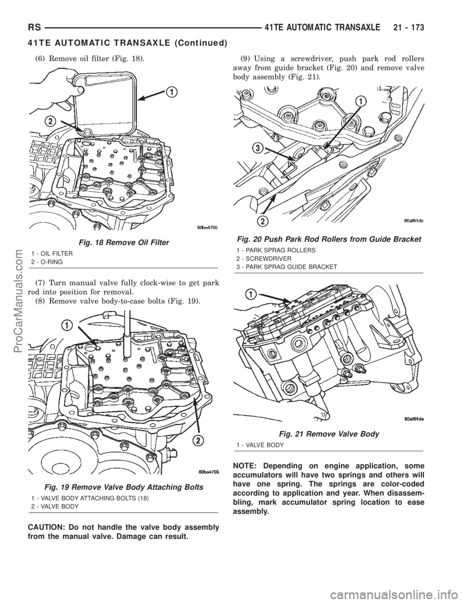
(6) Remove oil filter (Fig. 18).
(7) Turn manual valve fully clock-wise to get park
rod into position for removal.
(8) Remove valve body-to-case bolts (Fig. 19).
CAUTION: Do not handle the valve body assembly
from the manual valve. Damage can result.(9) Using a screwdriver, push park rod rollers
away from guide bracket (Fig. 20) and remove valve
body assembly (Fig. 21).
NOTE: Depending on engine application, some
accumulators will have two springs and others will
have one spring. The springs are color-coded
according to application and year. When disassem-
bling, mark accumulator spring location to ease
assembly.
Fig. 18 Remove Oil Filter
1 - OIL FILTER
2 - O-RING
Fig. 19 Remove Valve Body Attaching Bolts
1 - VALVE BODY ATTACHING BOLTS (18)
2 - VALVE BODY
Fig. 20 Push Park Rod Rollers from Guide Bracket
1 - PARK SPRAG ROLLERS
2 - SCREWDRIVER
3 - PARK SPRAG GUIDE BRACKET
Fig. 21 Remove Valve Body
1 - VALVE BODY
RS41TE AUTOMATIC TRANSAXLE21 - 173
41TE AUTOMATIC TRANSAXLE (Continued)
ProCarManuals.com
Page 1736 of 2399
(27) Setup tool 5058 as shown in (Fig. 43). Com-
press 2/4 clutch return spring (just enough to remove
snap ring) and remove snap ring.
NOTE: Verify that Tool 5058 is centered properly
over the 2/4 clutch retainer before compressing. If
necessary, fasten the 5058 bar to the bellhousing
flange with any combination of locking pliers and
bolts to center the tool properly.(28) Remove 2/4 clutch retainer (Fig. 44).
(29) Remove 2/4 clutch return spring (Fig. 45).
Fig. 42 Number 7 Bearing
1 - #7 NEEDLE BEARING
2 - REAR SUN GEAR
Fig. 43 Remove 2/4 Clutch Retainer Snap Ring
1 - TOOL 5058
2 - SCREWDRIVER
3 - SNAP RING
4 - 2/4 CLUTCH RETAINER
Fig. 44 2/4 Clutch Retainer
1 - 2/4 CLUTCH RETAINER
2 - 2/4 CLUTCH RETURN SPRING
Fig. 45 Remove 2/4 Clutch Return Spring
1 - 2/4 CLUTCH RETURN SPRING
RS41TE AUTOMATIC TRANSAXLE21 - 179
41TE AUTOMATIC TRANSAXLE (Continued)
ProCarManuals.com
Page 1739 of 2399
(38) Using Tool 6259, remove transfer shaft gear-
to-shaft nut and coned washer (Fig. 54) (Fig. 55).(39) Using tool L-4407A, remove transfer shaft
gear (Fig. 56).
(40) Remove transfer gear shim (select) (Fig. 57).
Fig. 54 Remove Transfer Shaft Gear Nut
1 - TRANSFER SHAFT GEAR
2 - OUTPUT GEAR
3 - SPECIAL TOOL 6259
Fig. 55 Transfer Shaft Gear Nut and Coned Washer
1 - TRANSFER SHAFT
2 - LOCK WASHER
3 - NUT
Fig. 56 Remove Transfer Shaft Gear
1 - SPECIAL TOOL L4407-6
2 - TRANSFER SHAFT GEAR
3 - SPECIAL TOOL L4407A
Fig. 57 Remove Transfer Shaft Gear and (Select)
Shim
1 - TRANSFER SHAFT GEAR
2 - BEARING CUP RETAINER
3 - SHIM (SELECT)
21 - 182 41TE AUTOMATIC TRANSAXLERS
41TE AUTOMATIC TRANSAXLE (Continued)
ProCarManuals.com
Page 1742 of 2399
(50) Remove stirrup and strap (Fig. 66).
(51) Using Tool 6259 (Fig. 67), remove output shaft
gear-to-shaft bolt and washer (Fig. 68).(52) Using Tool L4407A, and button 6055, remove
output gear from shaft (Fig. 69).
Fig. 66 Remove Stirrup Strap
1 - OUTPUT GEARBOLT
2 - RETAINING STRAP
3 - STIRRUP
Fig. 67 Remove Output Gear Bolt
1 - OUTPUT GEAR
2 - TOOL 6259
Fig. 68 Output Gear Bolt and Washer
1 - OUTPUT GEAR
2 - BOLT
3 - CONED LOCK WASHER
Fig. 69 Remove Output Gear
1 - OUTPUT GEAR
2 - BUTTON TOOL 6055
3 - WRENCHES
4 - TOOL L4407A
5 - BOLTS TOOL L4407±6
RS41TE AUTOMATIC TRANSAXLE21 - 185
41TE AUTOMATIC TRANSAXLE (Continued)
ProCarManuals.com
Page 1753 of 2399

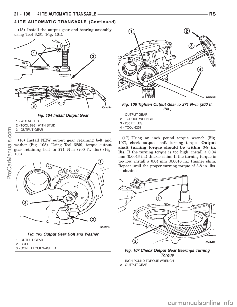
(15) Install the output gear and bearing assembly
using Tool 6261 (Fig. 104).
(16) Install NEW output gear retaining bolt and
washer (Fig. 105). Using Tool 6259, torque output
gear retaining bolt to 271 N´m (200 ft. lbs.) (Fig.
106).(17) Using an inch pound torque wrench (Fig.
107), check output shaft turning torque.Output
shaft turning torque should be within 3-8 in.
lbs.If the turning torque is too high, install a 0.04
mm (0.0016 in.) thicker shim. If the turning torque is
too low, install a 0.04 mm (0.0016 in.) thinner shim.
Repeat until the proper turning torque of 3-8 in. lbs.
is obtained.
Fig. 104 Install Output Gear
1 - WRENCHES
2 - TOOL 6261 WITH STUD
3 - OUTPUT GEAR
Fig. 105 Output Gear Bolt and Washer
1 - OUTPUT GEAR
2 - BOLT
3 - CONED LOCK WASHER
Fig. 106 Tighten Output Gear to 271 N²m (200 ft.
lbs.)
1 - OUTPUT GEAR
2 - TORQUE WRENCH
3 - 200 FT. LBS.
4 - TOOL 6259
Fig. 107 Check Output Gear Bearings Turning
Torque
1 - INCH-POUND TORQUE WRENCH
2 - OUTPUT GEAR
21 - 196 41TE AUTOMATIC TRANSAXLERS
41TE AUTOMATIC TRANSAXLE (Continued)
ProCarManuals.com
Page 1754 of 2399
(18) Install output gear stirrup with serrated side
out (Fig. 108).
(19) Install retaining strap.
(20) Install strap bolts but do not tighten at this
time (Fig. 109).(21) Rotate stirrup clockwise against flats of
retaining bolt (Fig. 110).
(22) Torque stirrup strap bolts to 23 N´m (200 in.
lbs.) (Fig. 111).
Fig. 108 Install Stirrup
1 - STIRRUP
2 - OUTPUT GEAR RETAINING BOLT
Fig. 109 Install Strap Bolts
1 - RETAINING STRAP
2 - STIRRUP
3 - RETAINING STRAP BOLTS
Fig. 110 Turn Stirrup Clockwise Against Bolt Flats
1 - RETAINING STRAP
2 - STIRRUP
Fig. 111 Tighten Stirrup Strap Bolts To 23 N´m (200
in.) lbs.)
1 - RETAINING STRAP
2 - STIRRUP
RS41TE AUTOMATIC TRANSAXLE21 - 197
41TE AUTOMATIC TRANSAXLE (Continued)
ProCarManuals.com
Page 1768 of 2399
NOTE: Depending on engine application, some
accumulators will have two springs, and others will
have one spring. The springs are color-coded for
application and year.
(62) Install underdrive and overdrive accumulators
(Fig. 155) (Fig. 156) (Fig. 157).
(63) Install valve body to transaxle (Fig. 158).
Rotate manual valve shaft fully clockwise to ease
installation. Make sure park rod rollers are posi-
tioned within park guide bracket.
Fig. 155 Accumulator (Underdrive)
1 - ACCUMULATOR PISTON (UNDERDRIVE)
2 - RETURN SPRINGS
3 - SEAL RING
4 - SEAL RING
Fig. 156 Accumulator (Overdrive)
1 - ACCUMULATOR PISTON (OVERDRIVE)
2 - RETURN SPRING
3 - SEAL RING
4 - SEAL RING
Fig. 157 Install Underdrive and Overdrive
Accumulators
1 - RETURN SPRING
2 - UNDERDRIVE CLUTCH ACCUMULATOR
3 - SEAL RING (2)
4 - OVERDRIVE CLUTCH ACCUMULATOR
Fig. 158 Install Valve Body
1 - VALVE BODY
RS41TE AUTOMATIC TRANSAXLE21 - 211
41TE AUTOMATIC TRANSAXLE (Continued)
ProCarManuals.com
Page 1771 of 2399

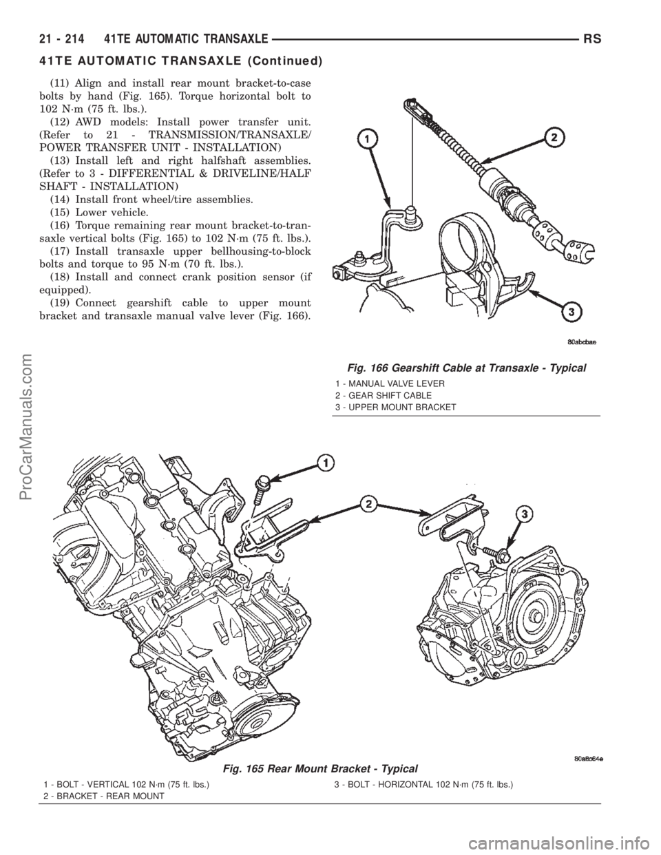
(11) Align and install rear mount bracket-to-case
bolts by hand (Fig. 165). Torque horizontal bolt to
102 N´m (75 ft. lbs.).
(12) AWD models: Install power transfer unit.
(Refer to 21 - TRANSMISSION/TRANSAXLE/
POWER TRANSFER UNIT - INSTALLATION)
(13) Install left and right halfshaft assemblies.
(Refer to 3 - DIFFERENTIAL & DRIVELINE/HALF
SHAFT - INSTALLATION)
(14) Install front wheel/tire assemblies.
(15) Lower vehicle.
(16) Torque remaining rear mount bracket-to-tran-
saxle vertical bolts (Fig. 165) to 102 N´m (75 ft. lbs.).
(17) Install transaxle upper bellhousing-to-block
bolts and torque to 95 N´m (70 ft. lbs.).
(18) Install and connect crank position sensor (if
equipped).
(19) Connect gearshift cable to upper mount
bracket and transaxle manual valve lever (Fig. 166).
Fig. 165 Rear Mount Bracket - Typical
1 - BOLT - VERTICAL 102 N´m (75 ft. lbs.)
2 - BRACKET - REAR MOUNT3 - BOLT - HORIZONTAL 102 N´m (75 ft. lbs.)
Fig. 166 Gearshift Cable at Transaxle - Typical
1 - MANUAL VALVE LEVER
2 - GEAR SHIFT CABLE
3 - UPPER MOUNT BRACKET
21 - 214 41TE AUTOMATIC TRANSAXLERS
41TE AUTOMATIC TRANSAXLE (Continued)
ProCarManuals.com