Page 1099 of 4323

CALIBRATION
1. ZERO POINT CALIBRATION OF MASTER CYLINDER
PRESSU")
DIDLY±01
F09750
DLC3
Ts
Tc
CG
± DIAGNOSTICSABS WITH EBD & BA & TRAC & VSC SYSTEM
DI±897
1091 Author�: Date�:
2005 SEQUOIA (RM1146U)
CALIBRATION
1. ZERO POINT CALIBRATION OF MASTER CYLINDER
PRESSURE, YAW RATE AND DECELERATION SEN-
SORS
HINT:
When having replaced the master cylinder pressure, yaw rate
and deceleration sensors and/or the ECU, make sure to per-
form master cylinder pressure, yaw rate and deceleration sen-
sors' zero point calibration.
NOTICE:
�While obtaining the zero point, do not vibrate the ve-
hicle by tilting, moving or shaking it and keep it in a
stationary condition. (Do not start the engine.)
�Be sure to do this on a level surface (within an inclina-
tion of 1 degree).
(a) Perform master cylinder pressure, yaw rate and decelera-
tion sensors zero point calibration.
(1) Using SST, connect terminals Ts and CG of the
DLC3.
SST 09843±18040
(2) Shift the shift lever to the P position.
(3) Turn the ignition switch to the ON position.
(4) Keep the vehicle in a stationary condition on a level
surface for 4 sec. or more.
(5) Keep your foot off the brake pedal.
Do not leave 4WD vehicles in the L4 position.
(6) Press the center diff. lock (TRAC OFF) switch 3
times within 3 seconds.
(7) Check that the VSC buzzer sounds for 3 seconds.
HINT:
�If the VSC buzzer does not sound, do the zero point cal-
ibration again and/or check the VSC buzzer circuit (See
page DI±1052).
�If the VSC buzzer does not sound, check for yaw rate and
deceleration sensor failure (See page DI±911).
(8) Turn the ignition switch OFF.
(9) Disconnect terminals Ts and CG of the DLC3.
(b) Perform steering angle sensor zero point calibration.
This calibration is carried out automatically by following
procedures below:
(1) Make sure the system is not in sensor check mode.
(2) Calibrate the steering angle sensor by driving the
vehicle in a straight line at more than 7 MPH (12
km/h) for 5 seconds.
Page 1101 of 4323

TEST MODE PROCEDURE
1. When not u")
DIDLZ±01
F09750
DLC3Ts
CG
BR3904
0.13 sec. 0.13 sec.
ON
OFF
± DIAGNOSTICSABS WITH EBD & BA & TRAC & VSC SYSTEM
DI±899
1093 Author�: Date�:
2005 SEQUOIA (RM1146U)
TEST MODE PROCEDURE
1. When not using the hand±held tester:
SENSOR CHECK (TEST MODE)
NOTICE:
When having replaced the master cylinder pressure, yaw
rate and deceleration sensors and/or the ECU, perform
zero point calibration of the master cylinder pressure, yaw
rate and deceleration sensors (See page DI±897).
HINT:
If the ignition switch is turned from the ON to the ACC or LOCK
position in test mode, test mode DTCs will be erased.
(a) Procedures for test mode:
(1) Turn the ignition switch OFF.
(2) Check that the shift lever is in the P position, and
turn the steering wheel to the neutral position.
(3) Using SST, connect terminals Ts and CG of the
DLC3.
SST 09843±18040
(4) Start the engine.
(5) Check that the ABS and VSC TRAC warning lights
blink.
HINT:
If the ABS and VSC TRAC warning lights do not blink, inspect
the ABS warning light circuit, VSC TRAC warning light circuit
and Ts terminal circuit.
(6) Keep the vehicle in a stationary condition on a level
surface for 4 sec. or more.
ABS warning light circuitDI±1021 or DI±1025
VSC TRAC warning light circuitDI±1027 or DI±1031
Ts terminal circuitDI±1057
Page 1104 of 4323

D05981
Hand±held
Tester
DLC3
BR3904
0.13 sec. 0.13 sec.
ON
OFF
F02135
Start Position
End PositionWithin ± 5° DI±902
± DIAGNOSTICSABS WITH EBD & BA & TRAC & VSC SYSTEM
1096 Author�: Date�:
2005 SEQUOIA (RM1146U)
2. When using the hand±held tester:
SENSOR CHECK (TEST MODE)
NOTICE:
When having replaced the master cylinder pressure, yaw
rate and deceleration sensors and/or ECU, perform zero
point calibration of the master cylinder pressure, yaw rate
and deceleration sensors (See page DI±897). Make sure
that this operation is done before performing the following.
(a) Procedures for test mode:
(1) Connect the hand±held tester to the DLC3.
(2) Check that the shift lever is in the P position, and
turn the steering wheel to the neutral position.
(3) Start the engine.
(4) Select the SIGNAL CHECK on the hand±held tes-
ter.
(5) Check that the ABS warning light and VSC TRAC
warning light blink.
HINT:
If the ABS and VSC TRAC warning lights do not blink, inspect
the ABS warning light circuit, VSC TRAC warning light circuit
and Ts terminal circuit.
(6) Keep the vehicle in a stationary condition on a level
surface for 4 sec. or more.
ABS warning light circuitDI±1021 or DI±1025
VSC TRAC warning light circuitDI±1027 or DI±1031
Ts terminal circuitDI±1057
(b) Check the yaw rate and deceleration sensor.
Shift the shift lever to the D position and drive the vehicle
at a vehicle speed of approx. 3 mph (5 km/h), turn the
steering wheel either to the left or right for 90° or more,
and turn the vehicle through 180 degrees. Check that the
VSC buzzer sounds for 3 seconds upon start off.
Stop the vehicle and shift the shift lever to the P position,
check that the VSC buzzer sounds again for 3 seconds.
Page 1124 of 4323

*1: As long as the following operations are not performed, the ABS warning light will not go")
DI±922
± DIAGNOSTICSABS WITH EBD & BA & TRAC & VSC SYSTEM
111 6 Author�: Date�:
2005 SEQUOIA (RM1146U)
*1: As long as the following operations are not performed, the ABS warning light will not go OFF only by re-
pairing the trouble area.
(1) Drive the vehicle at 12 mph (20 km/h) for 30 seconds or more and check that the ABS warning light goes
off.
(2) Clear the DTC (See page DI±911).
HINT:
There is a possibility that the hand±held tester cannot be used when the ABS warning light is always ON.
DTC chart of VSC system:
DTC No.
(See Page)Detection ItemTrouble Area
C1201/51
(DI±936)Engine control system malfunction�Engine control system
C1202/52
(DI±937)Brake fluid level warning switch circuit
�Brake fluid level
�Brake fluid level warning switch
�Brake fluid level warning switch circuit
�Skid control ECU
�CAN1 communication system
�Translate ECU
C1203/53 *1
(DI±942)Malfunction in CAN1 communication
�Skid control ECU
�CAN1 communication system
�ECM
�Translate ECU
C1207/37
(DI±522)Reverse gear signal failureECT
C1223/43
(DI±945)Malfunction in ABS control systemABS control system
C1231/31
(DI±946)Malfunction in steering angle sensor
�Steering angle sensor
�Steering angle sensor communication circuit
�Skid control ECU
�Translate ECU
�CAN communication system
C1232/32
(DI±951)Malfunction in deceleration sensor�Yaw rate (deceleration) sensor
�Yaw rate (deceleration) sensor circuit
C1234/34
(DI±954)Malfunction in yaw rate sensor�Yaw rate (deceleration) sensor
�Yaw rate (deceleration) sensor circuit
C1310/11
(DI±969)Open or short circuit in active brake booster solenoid circuit�Brake booster
�Active brake booster solenoid circuit
C1311/12
(DI±971)Open or short circuit in brake inhibit relay circuit�Brake inhibit relay
�Brake inhibit relay circuit
1335/35
(DI±946)Malfunction in steering angle sensor communication circuit
�Steering angle sensor
�Steering angle sensor communication circuit
�Skid control ECU
�Translate ECU
�CAN1 communication system
C1340/47*2
(DI±977)Center diff. lock circuit malfunction
�Center diff. lock position switch
�Center diff. lock position switch circuit
�Center diff. lock indicator light circuit
�Translate ECU
C1360/61
(DI±983)Malfunction in master cylinder pressure sensor�Master cylinder pressure sensor
�Master cylinder pressure sensor circuit
Page 1138 of 4323
DI±936
± DIAGNOSTICSABS WITH EBD & BA & TRAC & VSC SYSTEM
1130 Author�: Date�:
2005 SEQUOIA (RM1146U)
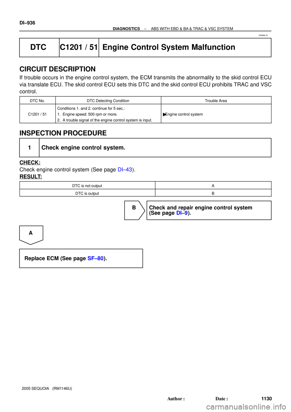
DTC C1201 / 51 Engine Control System Malfunction
CIRCUIT DESCRIPTION
If trouble occurs in the engine control system, the ECM transmits the abnormality to the skid control ECU
via translate ECU. The skid control ECU sets this DTC and the skid control ECU prohibits TRAC and VSC
control.
DTC No.DTC Detecting ConditionTrouble Area
C1201 / 51
Conditions 1. and 2. continue for 5 sec.:
1. Engine speed: 500 rpm or more.
2. A trouble signal of the engine control system is input.
�Engine control system
INSPECTION PROCEDURE
1 Check engine control system.
CHECK:
Check engine control system (See page DI±43).
RESULT:
DTC is not outputA
DTC is outputB
B Check and repair engine control system
(See page DI±9).
A
Replace ECM (See page SF±80).
DIDM6±01
Page 1140 of 4323
F19769
Translate ECU
VSC+
VSC±
IG17
T5
T511
1
T5B±RL
W
AA
J37
J38
A
J37B±R J/C
B±R B±RL
W 7
IL2
6
IL2
1
IL16
S1
2
S1
13
S1 ABS &VSC Actuator
(Skid Control ECU)
CANH
CANL
IG1
8
3C8
3A
B±R Instrument Panel J/B
4
1C
2
1C
3
1C
6
1C4
1F
11
1H
7
1J
1
1L ECU±IG
IGN1
AM1 B±R B±Y
W±R
W±LB±O
W±R
W
1 2Combination Meter
24
C6
Brake
1C5 W
8
ALTF10 Fusible
Link BlockEngine Room J/B
A W±R 1
2D1
2C
4
5
R±B R±B
B1 Brake Fluid Level
Warning SW
Y±L Y±LW±B 23
IA1
129
IA5O
A
A O
OJ43
J/C
IG Sub J/B No.4
LG±R
LG±R 4
4B4
4D
1P2 Parking
Brake SW
B
Battery 39
T5
24
T5
40
T5
4
T5 BRL
LVL2
GND
PKB2Sub J/B No.3
I18
Ignition SW
AM1 IG1
AM2 IG2 1
5 W±L
2
6
AM2
BB±R (CAN1 Circuit)
(CAN1 Circuit) DI±938
± DIAGNOSTICSABS WITH EBD & BA & TRAC & VSC SYSTEM
1132 Author�: Date�:
2005 SEQUOIA (RM1146U)
WIRING DIAGRAM
Page 1144 of 4323

7
T5
11
T5
14
T5
16
T57
IL2
6
IL2 L
WL
W6
S1
2
S1CANH
CANL
R
WL
W 1
J55
2
J551
J53
2
J53 J/C
33
E5
34
E5CANH
CANLECM (*1")
F19770
Translate ECU
VSC± VSC+
ENG±ENG+ABS & VSC Actuator
(Skid Control ECU)
7
T5
11
T5
14
T5
16
T57
IL2
6
IL2 L
WL
W6
S1
2
S1CANH
CANL
R
WL
W 1
J55
2
J551
J53
2
J53 J/C
33
E5
34
E5CANH
CANLECM (*1)
(*1)
(*2)
(*2)
(*1) CAN1 Circuit(*2) Vehicle CAN Circuit (*1)
(*1)
(*2)
(*2) DI±942
± DIAGNOSTICSABS WITH EBD & BA & TRAC & VSC SYSTEM
1136 Author�: Date�:
2005 SEQUOIA (RM1146U)
DTC C1203 / 53 Malfunction in CAN1 Communication
CIRCUIT DESCRIPTION
This circuit is used to send TRAC & VSC control information from the skid control ECU to the ECM (CAN
communication system) and engine control information from the ECM to the skid control ECU (CAN commu-
nication system).
The skid control ECU and ECM are connected to each other via the translate ECU using the CAN commu-
nication system.
DTC No.DTC Detecting ConditionTrouble Area
C1203 / 53Data cannot be transmitted and/or received to/from ECM
from translate ECU for a fixed time.
�Skid control ECU
�CAN1 communication system
�ECM
�Translate ECU
WIRING DIAGRAM
DI93J±04
Page 1145 of 4323
± DIAGNOSTICSABS WITH EBD & BA & TRAC & VSC SYSTEM
DI±943
1137 Author�: Date�:
2005 SEQUOIA (RM1146U)
INSPECTION PROCEDURE
1 Check engine control system.
CHECK:
Check engine control system (See page DI±43).
RESULT:
DTC is not outputA
DTC is outputB
B Repair engine control system according to the
output code (See page DI±58).
A
2 Check DTC of translate ECU.
CHECK:
Check DTC of the translate ECU (See page DI±911).
RESULT:
DTC is output (53, 65, 94)A
DTC is not outputB
B Go to step 4.
A
3 Check for open and short circuit in harness and connector between skid control
ECU and translate ECU (CAN1 circuit).
NG Repair or replace harness or connector
(CAN1 circuit).
OK

CANH
CANL
IG1
8
3C8
3A
B±R Instrum")