Page 2596 of 4323
EM0KT±11
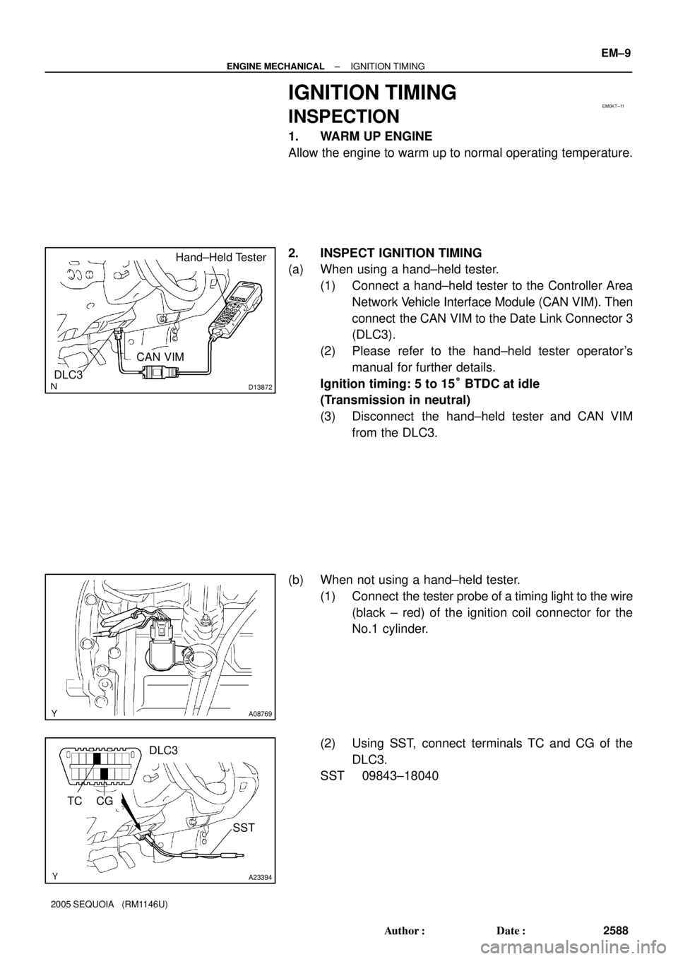
D13872
Hand±Held Tester
DLC3
CAN VIM
A08769
A23394
TC
SST
DLC3
CG
± ENGINE MECHANICALIGNITION TIMING
EM±9
2588 Author�: Date�:
2005 SEQUOIA (RM1146U)
IGNITION TIMING
INSPECTION
1. WARM UP ENGINE
Allow the engine to warm up to normal operating temperature.
2. INSPECT IGNITION TIMING
(a) When using a hand±held tester.
(1) Connect a hand±held tester to the Controller Area
Network Vehicle Interface Module (CAN VIM). Then
connect the CAN VIM to the Date Link Connector 3
(DLC3).
(2) Please refer to the hand±held tester operator's
manual for further details.
Ignition timing: 5 to 15° BTDC at idle
(Transmission in neutral)
(3) Disconnect the hand±held tester and CAN VIM
from the DLC3.
(b) When not using a hand±held tester.
(1) Connect the tester probe of a timing light to the wire
(black ± red) of the ignition coil connector for the
No.1 cylinder.
(2) Using SST, connect terminals TC and CG of the
DLC3.
SST 09843±18040
Page 2597 of 4323
A04459
EM±10
± ENGINE MECHANICALIGNITION TIMING
2589 Author�: Date�:
2005 SEQUOIA (RM1146U)
(3) Using a timing light, check the ignition timing.
Ignition timing: 5 to 15° BTDC at idle
(Transmission in neutral)
(4) Remove the SST from the DLC3.
SST 09843±18040
(5) Disconnect the timing light from the engine.
Page 2598 of 4323

IDLE SPEED
INSPECTION
1. INITIAL CONDITIONS
(a)")
EM1X3±01
D13872
Hand±Held Tester
DLC3
CAN VIM
A23395
DLC3
TA C
SST
± ENGINE MECHANICALIDLE SPEED
EM±11
2590 Author�: Date�:
2005 SEQUOIA (RM1146U)
IDLE SPEED
INSPECTION
1. INITIAL CONDITIONS
(a) Engine at normal operating temperature
(b) Air cleaner installed
(c) All pipes and hoses of air induction system connected
(d) All accessories switched OFF
(e) All vacuum lines properly connected
(f) SFI system wiring connectors fully plugged
(g) iCorrect gnition timing
(h) Transmission in neutral
(i) Air conditioning switched OFF
2. INSPECT ENGINE IDLE SPEED
(a) When using a hand±held tester.
(1) Connect a hand±held tester to the Controller Area
Network Vehicle Interface Module (CAN VIM). Then
connect the CAN VIM to the Date Link Connector 3
(DLC3).
(2) Please refer to the hand±held tester operator's
manual for further details.
(3) Race the engine speed at 2,500 rpm for approx. 90
seconds.
(4) Check the idle speed.
Idle speed: 700 ± 50 rpm
(Transmission in neutral)
If the idle speed is not as specified, check the air intake system.
(5) Disconnect the hand±held tester and CAN VIM
from the DLC3.
(b) When not using a hand±held tester.
(1) Using SST, connect the tachometer probe to termi-
nal TAC of the DLC3.
SST 09843±18030
(2) Race the engine at 2,500 rpm for approx. 90 se-
conds.
(3) Check the idle speed.
Idle speed: 700 ± 50 rpm
(Transmission in neutral )
If the idle speed is not as specified, check the air intake system.
Page 2599 of 4323
EM±12
± ENGINE MECHANICALIDLE SPEED
2591 Author�: Date�:
2005 SEQUOIA (RM1146U)
(4) Disconnect the tachometer from the DLC3.
Page 2725 of 4323
 CONTROL SYSTEM
EC±9
2717 Author�: Date�:
2005 SEQUOIA (RM1146U)
INSP")
EC0JL±03
B17594
Gasket
B06544
Vacuum Gauge
D13872
Hand±Held Tester
DLC3
CAN VIM
± EMISSION CONTROLEVAPORATIVE EMISSION (EVAP) CONTROL SYSTEM
EC±9
2717 Author�: Date�:
2005 SEQUOIA (RM1146U)
INSPECTION
1. INSPECT LINES AND CONNECTIONS
Visually check for loose connections, sharp bends or damage.
2. INSPECT FUEL TANK
Visually check for deformation, cracks or fuel leakage.
3. INSPECT FUEL TANK CAP
Visually check if the cap and/or gasket are deformed or dam-
aged.
If necessary, repair or replace the cap.
4. INSPECT EVAP SYSTEM LINE
(a) Warm up the engine to normal operating temperature and
stop the engine.
(b) Install a vacuum gauge (EVAP control system test equip-
ment vacuum gauge) into the EVAP service port on the
purge line.
(c) When using a hand±held tester:
Operation of the VSV for EVAP.
(1) Connect a hand±held tester to the Controller Area
Network Vehicle Interface Module (CAN VIM). Then
connect the CAN VIM to the Date Link Connector 3
(DLC3).
(2) Start the engine.
(3) Turn the hand±held tester ON.
(4) Enter the following menus: DIAGNOSIS / EN-
HANCED OBDII/ ACTIVE TEST / EVAP VAV
(ALONE)
Page 2726 of 4323
 CONTROL SYSTEM
2718 Author�: Date�:
2005 SEQUOIA (RM1146U)
(d) When not using a hand±held tester:
Ope")
B16489
Battery
B06545
Vacuum Gauge
B17595
EC±10
± EMISSION CONTROLEVAPORATIVE EMISSION (EVAP) CONTROL SYSTEM
2718 Author�: Date�:
2005 SEQUOIA (RM1146U)
(d) When not using a hand±held tester:
Operation of the VSV for the EVAP.
(1) Disconnect the VSV for the EVAP connector.
(2) Connect leads from the positive (+) and negative (±)
battery terminals to the VSV for EVAP terminals.
(3) Start the engine.
(e) Check the vacuum when the engine idles.
Vacuum:
Maintain between 0.368 and 19.713 in.Hg (5 to 268
in.Aq) for over 5 seconds
HINT:
If the vacuum does not change, the hose connecting the VSV
and the service port is loose or blocked, or the VSV is malfunc-
tioning.
(f) When using a hand±held tester:
Conclude operation of the VSV for EVAP.
(1) Stop the engine.
(2) Disconnect the hand±held tester from the DLC3.
(g) When not using a hand±held tester:
Conclude operation of the VSV for EVAP.
(1) Stop the engine.
(2) Disconnect the positive (+) and negative (±) leads
of the battery from the VSV for EVAP terminals.
(3) Connect the VSV for EVAP connector.
(h) Disconnect the vacuum gauge from the EVAP service
port on the purge line.
(i) Connect a pressure gauge to the EVAP service port on
the purge line.
(j) Check the pressure.
(1) Prepare a rubber hose that has an inside diameter
of 15 to 18.5 mm.
(2) Disconnect the atmospheric side hose of the pump
module.
(3) Connect the prepared rubber hose to the pump
module, and pinch the rubber hose with the clip to
prevent air from entering into the canister passage.
Page 2748 of 4323

(j) Check that there is any fuel leak after maintenance any-
wh")
D13872
Hand±Held Tester
DLC3
CAN VIM
B16500
Fuel Return Hose
Pinch
SF±6
± SFISFI SYSTEM
2740 Author�: Date�:
2005 SEQUOIA (RM1146U)
(j) Check that there is any fuel leak after maintenance any-
where on the fuel system.
(1) Connect a hand±held tester to the Controller Area
Network Vehicle Interface Module (CAN VIM). Then
connect the CAN VIM to the Date Link Connector 3
(DLC3).
(2) Turn the ignition switch ON and push the hand±held
tester main switch ON.
NOTICE:
Do not start the engine.
(3) Enter the following menus: DIAGNOSIS / EN-
HANCED OBDII / ACTIVE TEST / FUEL PUMP /
SPD.
(4) Please refer to the hand±held tester operator's
manual for further details.
(5) Pinch the fuel return hose.
The pressure in the high pressure line will rise to
approx. 392 kPa (4 kgf/cm
2, 57 psi). In this state,
check to see that there are no leaks from any part
of the fuel system.
NOTICE:
Always pinch the hose. Avoid bending as it may cause the
hose to crack.
(6) Turn the ignition switch OFF.
(7) Disconnect the hand±held tester and CAN VIM
from the DLC3.
Page 2749 of 4323

Front
Fuel
Pipe
Gasket SST
(Union)SST
(Adaptor)
± SFIFUEL PUMP
SF±7
2741 Author�: Date�:
2005 SEQUO")
D13872
Hand±Held Tester
DLC3
CAN VIM
SF12Y±05
B16497
Up
Pulsation
DamperScrew
B16528
SST
(Gauge)
Front
Fuel
Pipe
Gasket SST
(Union)SST
(Adaptor)
± SFIFUEL PUMP
SF±7
2741 Author�: Date�:
2005 SEQUOIA (RM1146U)
FUEL PUMP
ON±VEHICLE INSPECTION
1. CHECK FUEL PUMP OPERATION
(a) Connect a hand±held tester to the Controller Area Net-
work Vehicle Interface Module (CAN VIM). Then connect
the CAN VIM to the Date Link Connector 3 (DLC3).
(b) Turn the ignition switch ON, and push the hand±held tes-
ter main switch ON.
NOTICE:
Do not start the engine.
(c) Enter the following menus: DIAGNOSIS / ENHANCED
OBDII / ACTIVE TEST / FUEL PUMP / SPD
(d) Please refer to the hand±held tester operator's manual
for further details.
(e) Check that the pulsation damper screw rises when the
fuel pump operates.
If operation is not as specified, check the fusible link, fuses, EFI
main relay, fuel pump, ECM and wiring connections.
(f) Turn the ignition switch off.
(g) Disconnect the hand±held tester and CAN VIM from the
DLC3.
2. CHECK FUEL PRESSURE
(a) Check the battery positive voltage is 12 V or more.
(b) Disconnect the negative (±) terminal cable from the bat-
tery.
(c) Remove the front fuel pipe from the LH delivery pipe. (See
page SF±27)
(d) Install the front fuel pipe and SST (pressure gauge) to the
delivery pipe with the 3 lower gaskets and SST (adaptor).
SST 09268±45014 (09268±41190, 90405±06167)
Torque: 39 N´m (400 kgf´cm, 29 ft´lbf)
(e) Wipe off any splattered gasoline.
(f) Reconnect the negative (±) terminal cable to the battery.
(g) Connect a hand±held tester to the DLC3. (See step 1 in
check fuel pump operation (a) to (e))