Page 3355 of 4323

3347 Author�: Date�:
2005 SEQUOIA (RM1146U)
INSPECTION
1. VEHICLE NOT INVOLVE")
RS0LH±05
H16230
Cross Section
H23933
RS±64
± SUPPLEMENTAL RESTRAINT SYSTEMSIDE AIRBAG ASSEMBLY (Manual Adjuster Type)
3347 Author�: Date�:
2005 SEQUOIA (RM1146U)
INSPECTION
1. VEHICLE NOT INVOLVED IN COLLISION
(a) Perform a diagnostic system check (see page DI±1147).
(b) With the front seat airbag assy installed on the vehicle,
perform a visual check. If there are any defects as men-
tioned below, replace the front seatback assy with a new
one:
Cuts, minute cracks or marked discoloration on the front
seatback assy around the front seat airbag assy.
2. VEHICLE INVOLVED IN A COLLISION AND AIRBAG IS
NOT DEPLOYED
(a) Perform a diagnostic system check (see page DI±1147).
(b) Perform a visual check which includes the following items
with the seatback assembly removed from the vehicle.
�Cuts, tears and cracks on the side airbag assembly.
�Cuts and cracks in wire harness, and chipping in
connectors.
CAUTION:
For removal and installation of the front seatback assem-
bly, see page RS±61 and RS±67. Be sure to follow the cor-
rect procedure.
Page 3356 of 4323
RS0LI±03
± SUPPLEMENTAL RESTRAINT SYSTEMSIDE AIRBAG ASSEMBLY (Manual Adjuster Type)
RS±65
3348 Author�: Date�:
2005 SEQUOIA (RM1146U)
DISPOSAL
See page RS±50.
Page 3357 of 4323

3349 Author�: Date�:
2005 SEQUOIA (RM1146U)
REPLACEMENT
REPLACEMENT REQUIREMENTS
In the following cases,")
RS0LJ±03
RS±66
± SUPPLEMENTAL RESTRAINT SYSTEMSIDE AIRBAG ASSEMBLY (Manual Adjuster Type)
3349 Author�: Date�:
2005 SEQUOIA (RM1146U)
REPLACEMENT
REPLACEMENT REQUIREMENTS
In the following cases, replace the seat frame assembly or seatback cover with a new one.
CaseReplacing part
The side airbag has been deployed.Seat assembly
The side airbag assembly has been found to be faulty in troubleshooting.Seat frame assembly
The side airbag assembly has been found to have cuts while checking items
(See page RS±64).Seat frame assembly
The seatback cover has been found to have cuts and frayed seams while
checking items
(See page RS±64).
Seatback cover
The side airbag assembly has been found to be faulty while checking items
(See page RS±64).Seat frame assembly
The seatback cover has been found to be faulty while checking items
(See page RS±64).Seatback cover
The seatback assembly has been dropped.Seat frame assembly
CAUTION:
For removal and installation of the seat frame assembly, see page RS±61 and RS±67. Be sure to fol-
low the correct procedure.
Page 3358 of 4323

RS±67
3350 Author�: Date�:
2005 SEQUOIA (RM1146U)
INSTALLATION
HINT:
�Use the same")
RS11E±01
H24319
H24339
H24338Hog Ring
± SUPPLEMENTAL RESTRAINT SYSTEMSIDE AIRBAG ASSEMBLY (Manual Adjuster Type)
RS±67
3350 Author�: Date�:
2005 SEQUOIA (RM1146U)
INSTALLATION
HINT:
�Use the same procedures for the RH side and LH side.
�The procedures listed below are for the LH side.
NOTICE:
�If the side airbag assembly has been dropped, or
there are cracks, dents or other defects in the case or
connector, replace the side airbag assembly with a
new one.
�When installing the side airbag assembly, take care
it is not pinched between other parts.
�Never use airbag parts from another vehicle. When
replacing parts, replace them with new ones.
1. INSTALL SEATBACK COVER
(a) Install the seatback cover to the seatback pad.
(b) Install the 2 headrest supports.
(c) Turn up the seatback cover and install the hog rings.
2. INSTALL SEATBACK COVER AND PAD
(a) Install the seatback cover and pad to the seat frame as-
sembly.
(b) Install the hog rings to the seat frame assembly.
(c) Install the hog rings to the seat frame assembly.
Page 3359 of 4323
H24861
H24337
H24316
H24334ClawClip RS±68
± SUPPLEMENTAL RESTRAINT SYSTEMSIDE AIRBAG ASSEMBLY (Manual Adjuster Type)
3351 Author�: Date�:
2005 SEQUOIA (RM1146U)
(d) w/ Side airbag:
Connect the seatback cover bracket to the seat frame as-
sembly with the nut.
Torque: 5.5 N´m (56 kgf´cm, 49 in.´lbf)
(e) Close the fastener.
(f) Install the hog rings to the seat frame assembly.
3. INSTALL ARMREST ASSEMBLY
(a) Install the spacer to the armrest assembly.
(b) Install the armrest assembly, armrest lock plate and arm-
rest spacer with the bolt.
Torque: 37 N´m (377 kgf´cm, 27 ft´lbf)
HINT:
Install the armrest lock plate as shown in the illustration.
(c) Install the armrest cap.
4. INSTALL FRONT SEAT INNER BELT
(a) Install the front seat inner belt with the nut.
Torque: 42 N´m (428 kgf´cm, 31 ft´lbf)
(b) Connect the connectors and wire harness clamps.
5. INSTALL SEAT CUSHION INNER SHIELD
Install the seat cushion inner shield with the screw.
Page 3360 of 4323

RS±69
3352 Author�: Date�:
2005 SEQUOIA (RM1146U)
6. INSTALL VERTICAL ADJUSTER HANDLE
(a) Install")
H24333
H24331ClawsClip
± SUPPLEMENTAL RESTRAINT SYSTEMSIDE AIRBAG ASSEMBLY (Manual Adjuster Type)
RS±69
3352 Author�: Date�:
2005 SEQUOIA (RM1146U)
6. INSTALL VERTICAL ADJUSTER HANDLE
(a) Install the vertical adjuster handle with the 2 screws.
(b) Install the vertical adjuster handle cap.
7. INSTALL RECLINING ADJUSTER RELEASE HANDLE
8. INSTALL SEAT CUSHION OUTER SHIELD
Install the seat cushion outer shield with the screw.
9. INSTALL HEADREST
10. INSTALL FRONT SEAT
Mount the front seat to the vehicle.
NOTICE:
Be careful not to damage the body.
(a) w/ Side airbag:
Connect the airbag connector.
(b) Connect the connectors.
(c) Slide the front seat to the rearmost position.
(d) Tighten the bolts on the front side temporarily, starting
from the bolt on the inner side.
(e) Tighten them completely.
Torque: 37 N´m (377 kgf´cm, 27 ft´lbf)
(f) Slide the front seat to the foremost position.
(g) Tighten the bolts on the rear side temporarily, starting
from the bolt on the inner side.
(h) Tighten them completely.
Torque: 37 N´m (377 kgf´cm, 27 ft´lbf)
11. INSTALL SEAT TRACK COVERS
12. CONNECT CABLE TO NEGATIVE BATTERY TERMI-
NAL
13. PERFORM INITIALIZATION (SEE PAGE BE±77)
Some system need initialization when disconnecting the cable
from the negative battery terminal.
14. INSPECT SRS WARNING LIGHT (SEE PAGE DI±1137)
Page 3361 of 4323
RS0N2±16
H23896
Curtain Shield
Airbag Assembly
N´m (kgf´cm, ft´lbf): Specified torque
9.8 (100, 7)
9.8 (100, 7)
9.8 (100, 7)
RS±70
± SUPPLEMENTAL RESTRAINT SYSTEMCURTAIN SHIELD AIRBAG ASSEMBLY
3353 Author�: Date�:
2005 SEQUOIA (RM1146U)
CURTAIN SHIELD AIRBAG ASSEMBLY
COMPONENTS
Page 3362 of 4323
RS11F±01
H23897
± SUPPLEMENTAL RESTRAINT SYSTEMCURTAIN SHIELD AIRBAG ASSEMBLY
RS±71
3354 Author�: Date�:
2005 SEQUOIA (RM1146U)
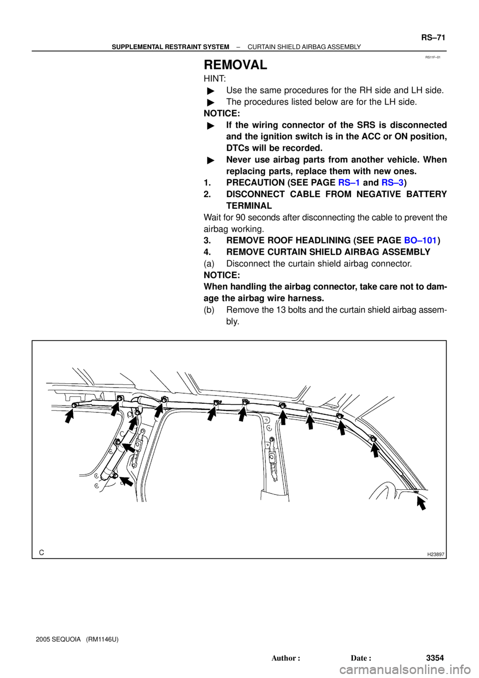
REMOVAL
HINT:
�Use the same procedures for the RH side and LH side.
�The procedures listed below are for the LH side.
NOTICE:
�If the wiring connector of the SRS is disconnected
and the ignition switch is in the ACC or ON position,
DTCs will be recorded.
�Never use airbag parts from another vehicle. When
replacing parts, replace them with new ones.
1. PRECAUTION (SEE PAGE RS±1 and RS±3)
2. DISCONNECT CABLE FROM NEGATIVE BATTERY
TERMINAL
Wait for 90 seconds after disconnecting the cable to prevent the
airbag working.
3. REMOVE ROOF HEADLINING (SEE PAGE BO±101)
4. REMOVE CURTAIN SHIELD AIRBAG ASSEMBLY
(a) Disconnect the curtain shield airbag connector.
NOTICE:
When handling the airbag connector, take care not to dam-
age the airbag wire harness.
(b) Remove the 13 bolts and the curtain shield airbag assem-
bly.


: Specified torque
9.8 (100, 7)
9.8 (100, 7)
9.8 (100, 7)
RS±70
± SUPPLEMENTAL RESTRAINT SYSTEMCURTAIN SHIELD AIRBAG ASSEMBLY
3")