Page 3032 of 4323

INSTALLATION
1. INSTALL STEERING KNUCKLE
(a) 4WD:
Insert the drive shaft into the axle hub and temp")
SA23J±05
SA±28
± SUSPENSION AND AXLEFRONT AXLE HUB
3024 Author�: Date�:
2005 SEQUOIA (RM1146U)
INSTALLATION
1. INSTALL STEERING KNUCKLE
(a) 4WD:
Insert the drive shaft into the axle hub and temporarily tighten the nut.
NOTICE:
Be careful not to damage the oil seal and drive shaft boot.
(b) Connect the steering knuckle to the upper suspension arm.
(c) Install the nut and a new cotter pin.
If the holes for the cotter pin are not aligned, tighten the nut further up to 60°.
Torque: 105 N´m (1,100 kgf´cm, 77 ft´lbf)
2. CONNECT LOWER BALL JOINT
Connect the lower ball joint to the steering knuckle with the 4 bolts.
Torque: 65 N´m (663 kgf´cm, 48 ft´lbf)
3. INSTALL SHOCK ABSORBER (See page SA±70)
4. INSTALL BRAKE CALIPER
(a) Install the disc, brake caliper and 2 bolts.
Torque: 123 N´m (1,250 kgf´cm, 90 ft´lbf)
(b) Install the brake line clamp to the steering knuckle with the bolt.
Torque: 28 N´m (285 kgf´cm, 21 ft´lbf)
5. CONNECT SPEED SENSOR AND WIRE HARNESS CLAMP
Connect the speed sensor and wire harness clamp to the steering knuckle with the 2 bolts.
Torque: 8.0 N´m (82 kgf´cm, 71 ft´lbf)
6. 4WD:
INSTALL DRIVE SHAFT LOCK NUT
(a) While applying the brakes, tighten the nut.
Torque: 235 N´m (2,400 kgf´cm, 173 ft´lbf)
(b) Install the lock cap and a new cotter pin.
If the holes for the cotter pin are not aligned, tighten the nut further up to 60°.
7. INSTALL GREASE CAP
8. INSTALL FRONT WHEEL
Torque: 110 N´m (1,150 kgf´cm, 83 ft´lbf)
9. DEPRESS BRAKE PEDAL SEVERAL TIMES
10. CHECK FRONT WHEEL ALIGNMENT (See page SA±4)
11. CHECK SPEED SENSOR SIGNAL (See page DI±899)
12. PERFORM ZERO POINT CALIBRATION OF STEERING ANGLE, MASTER CYLINDER PRES-
SURE, YAW RATE AND DECELERATION SENSORS (See page DI±897)
Page 3033 of 4323

FRONT WHEEL HUB BOLT
REPLACEMENT
1. REMOVE FRONT WHEEL
2. RE")
SA24P±03
F07264
R13372
SST
R13373WasherNut
± SUSPENSION AND AXLEFRONT WHEEL HUB BOLT
SA±29
3025 Author�: Date�:
2005 SEQUOIA (RM1146U)
FRONT WHEEL HUB BOLT
REPLACEMENT
1. REMOVE FRONT WHEEL
2. REMOVE BRAKE CALIPER AND DISC
(a) Remove the bolt and brake line clamp from the steering
knuckle.
(b) Remove the 2 bolts, brake caliper and disc.
(c) Support the brake caliper securely.
3. REMOVE HUB BOLT
Using SST and a screwdriver or an equivalent, remove the hub
bolt.
SST 09650±17011
4. INSTALL HUB BOLT
(a) Install a washer and nut to a new hub bolt as shown in the
illustration.
(b) Using a screwdriver or an equivalent to hold, install the
hub bolt by torquing the nut.
(c) Remove the nut and washer.
5. INSTALL BRAKE DISC AND CALIPER
(a) Install the brake disc, caliper and 2 bolts.
Torque: 123 N´m (1,250 kgf´cm, 90 ft´lbf)
(b) Install the brake line clamp to the steering knuckle with the
bolt.
Torque: 28 N´m (285 kgf´cm, 21 ft´lbf)
6. INSTALL FRONT WHEEL
Torque: 110 N´m (1,150 kgf´cm, 83 ft´lbf)
7. DEPRESS BRAKE PEDAL SEVERAL TIMES
Page 3035 of 4323
SA24L±03
F06624
R12863
SST
R13233
± SUSPENSION AND AXLEFRONT DRIVE SHAFT
SA±31
3027 Author�: Date�:
2005 SEQUOIA (RM1146U)
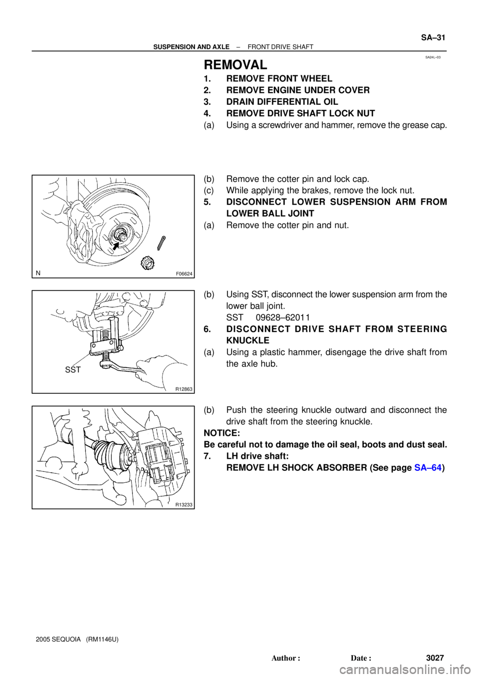
REMOVAL
1. REMOVE FRONT WHEEL
2. REMOVE ENGINE UNDER COVER
3. DRAIN DIFFERENTIAL OIL
4. REMOVE DRIVE SHAFT LOCK NUT
(a) Using a screwdriver and hammer, remove the grease cap.
(b) Remove the cotter pin and lock cap.
(c) While applying the brakes, remove the lock nut.
5. DISCONNECT LOWER SUSPENSION ARM FROM
LOWER BALL JOINT
(a) Remove the cotter pin and nut.
(b) Using SST, disconnect the lower suspension arm from the
lower ball joint.
SST 09628±62011
6. DISCONNECT DRIVE SHAFT FROM STEERING
KNUCKLE
(a) Using a plastic hammer, disengage the drive shaft from
the axle hub.
(b) Push the steering knuckle outward and disconnect the
drive shaft from the steering knuckle.
NOTICE:
Be careful not to damage the oil seal, boots and dust seal.
7. LH drive shaft:
REMOVE LH SHOCK ABSORBER (See page SA±64)
Page 3040 of 4323

INSTALLATION
1. INSTALL DRIVE SHAFT TO DIFFERENTIAL
(a) Install a new snap ring to the inboard jo")
SA14I±10
SA±36
± SUSPENSION AND AXLEFRONT DRIVE SHAFT
3032 Author�: Date�:
2005 SEQUOIA (RM1146U)
INSTALLATION
1. INSTALL DRIVE SHAFT TO DIFFERENTIAL
(a) Install a new snap ring to the inboard joint shaft.
(b) Apply gear oil to the inboard joint shaft and differential case sliding surface.
(c) Set the snap ring with opening side facing downward.
(d) Using a brass bar and hammer, install the drive shaft.
NOTICE:
Be careful not to damage the dust cover and oil seal.
HINT:
Whether the inboard joint shaft is in contact with the pinion shaft or not can be known from the sound or feel-
ing when driving.
(e) Check that there is 2 ± 3 mm (0.08 ± 0.12 in.) of play in the axial direction.
(f) Check that the drive shaft cannot be removed by hand.
2. LH drive shaft:
INSTALL LH SHOCK ABSORBER (See page SA±70)
3. CONNECT DRIVE SHAFT TO STEERING KNUCKLE
NOTICE:
Be careful not to damage the oil seal, boots and dust seal.
4. CONNECT LOWER SUSPENSION ARM TO LOWER BALL JOINT
(a) Connect the lower suspension arm to the lower ball joint.
(b) Install the nut and a new cotter pin.
If the holes for the cotter pin are not aligned, tighten the nut further up to 60°.
HINT:
Face the hole for the cotter pin forward.
Torque: 140 N´m (1,450 kgf´cm, 103 ft´lbf)
5. INSTALL DRIVE SHAFT LOCK NUT
(a) While applying brakes, install the nut.
Torque: 235 N´m (2,400 kgf´cm, 173 ft´lbf)
(b) Install the lock cap and a new cotter pin.
If the holes for the cotter pin are not aligned, tighten the nut further up to 60°.
6. FILL DIFFERENTIAL WITH HYPOID GEAR OIL (See page SA±38)
7. INSTALL ENGINE UNDER COVER
8. INSTALL FRONT WHEEL
Torque: 110 N´m (1,150 kgf´cm, 83 ft´lbf)
Page 3068 of 4323
SA23R±03
F14315
R12773
SA±64
± SUSPENSION AND AXLEFRONT SHOCK ABSORBER
3060 Author�: Date�:
2005 SEQUOIA (RM1146U)
REMOVAL
1. REMOVE FRONT WHEEL
2. DISCONNECT SHOCK ABSORBER FROM LOWER
SUSPENSION ARM
(a) Remove the shock absorber lower side set nut and wash-
er.
NOTICE:
Do not remove the bolt.
(b) Pry down the lower suspension arm to remove the bolt
and disconnect the shock absorber.
3. REMOVE SHOCK ABSORBER WITH COIL SPRING
Remove the 3 nuts and shock absorber with the coil spring.
Page 3074 of 4323
SA182±06
SA±70
± SUSPENSION AND AXLEFRONT SHOCK ABSORBER
3066 Author�: Date�:
2005 SEQUOIA (RM1146U)
INSTALLATION
1. INSTALL SHOCK ABSORBER WITH COIL SPRING
(a) Install the upper side of the shock absorber to the chassis frame with the 3 nuts.
Torque: 64 N´m (650 kgf´cm, 47 ft´lbf)
(b) Connect the lower side of the shock absorber to the lower suspension arm with the bolt, washer and
nut.
Torque: 135 N´m (1,400 kgf´cm, 100 ft´lbf)
2. INSTALL FRONT WHEEL
Torque: 110 N´m (1,150 kgf´cm, 83 ft´lbf)
Page 3078 of 4323

INSTALLATION
1. INSTALL UPPER SUSPENSION ARM
Install the upper suspension arm with the 2")
SA187±06
SA±74
± SUSPENSION AND AXLEFRONT UPPER SUSPENSION ARM
3070 Author�: Date�:
2005 SEQUOIA (RM1146U)
INSTALLATION
1. INSTALL UPPER SUSPENSION ARM
Install the upper suspension arm with the 2 washers, bolt and nut.
Torque: 98 N´m (1,000 kgf´cm, 72 ft´lbf)
HINT:
After stabilizing the suspension, torque the nut.
2. INSTALL BRAKE AND FUEL LINE CLAMP
Torque: 5.5 N´m (56 kgf´cm, 49 in.´lbf)
3. INSTALL FENDER APRON SEAL REAR
4. CONNECT UPPER BALL JOINT
(a) Connect the upper ball joint to the upper suspension arm.
(b) Install the nut and a new cotter pin.
If the holes for the cotter pin are not aligned, tighten the nut further up to 60°.
Torque: 105 N´m (1,100 kgf´cm, 77 ft´lbf)
5. CONNECT SPEED SENSOR WIRE HARNESS CLAMPS
Torque: 8.0 N´m (82 kgf´cm, 71 in.´lbf)
6. INSTALL SHOCK ABSORBER WITH COIL SPRING (See page SA±70)
7. CHECK FRONT WHEEL ALIGNMENT (See page SA±4)
8. PERFORM ZERO POINT CALIBRATION OF STEERING ANGLE, MASTER CYLINDER PRES-
SURE, YAW RATE AND DECELERATION SENSORS (See page DI±897)
Page 3080 of 4323
SA23X±03
R13425
SST
F07278
F07273
F14315
SA±76
± SUSPENSION AND AXLEFRONT LOWER SUSPENSION ARM
3072 Author�: Date�:
2005 SEQUOIA (RM1146U)
REMOVAL
1. REMOVE RH AND LH FRONT WHEELS
2. DISCONNECT RH AND LH TIE ROD ENDS
(a) Remove the cotter pin and nut.
(b) Using SST, disconnect the tie rod end from the lower ball
joint.
SST 09610±20012
(c) Use the same procedures described above to the other
side.
3. REMOVE POWER STEERING GEAR SET BOLTS AND
NUTS
4. DISCONNECT STABILIZER BAR LINK FROM LOWER
SUSPENSION ARM
Remove the nut and disconnect the stabilizer bar link from the
lower suspension arm.
HINT:
If the ball joint turns together with the nut, use a hexagon (6 mm)
wrench to hold the stud.
5. DISCONNECT SHOCK ABSORBER FROM LOWER
SUSPENSION ARM
(a) Remove the shock absorber lower side set nut and wash-
er.
NOTICE:
Do not remove the bolt.
(b) Pry down the lower suspension arm to remove the bolt
and disconnect the shock absorber.